1
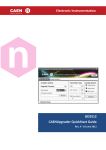
CAEN
Tools for Discovery
Electronic Instrumentation
ggggggggggggggggggggggggggggggggggg gggggggggggggggggggggggggggggggggggggg
14 January 2015
Rev. 7 -
UM2463
GECO2020 GEneral COntrol Software for CAEN HV
Power Supplies
Rev. 8 - 3 April 2015
Purpose of this User Manual
This User’s Manual contains the full description of the GECO2020 GEneral COntrol Software for CAEN HV Power
Supplies.
Change Document Record
Date
Rev.
Changes
23 May 2013
0
First release
13 June 2013
1
N568E Support
13 September 2013 2
Updated to rel. 1.1.2; N568E no longer supported
8 November 2013
3
Updated to rel. 1.2; DT55xx supported
22 January 2014
4
Updated to rel. 1.3; New Advanced Features (Scripting)
14 February 2014
5
Updated to rel. 1.4; SYx527 auto detection, graphical trip setting
10 July 2014
6
Updated to rel. 1.5; System RESET FLAG and DT55xx parameters
14 January 2015
7
Updated to rel. 1.6; NIM, DESKTOP, Rack, VME, DT55xx system Log; R14xx support; VSET, ISET offset
3 April 2015
8
Updated enhancement activation
Symbols, abbreviated terms and notation
T.B.D.
Reference Document
T.B.D.
CAEN S.p.A.
Via Vetraia, 11 55049 Viareggio (LU) - ITALY
Tel. +39.0584.388.398 Fax +39.0584.388.959
[email protected]
www.caen.it
© CAEN SpA – 2011
Disclaimer
No part of this manual may be reproduced in any form or by any means, electronic, mechanical, recording, or
otherwise, without the prior written permission of CAEN SpA.
The information contained herein has been carefully checked and is believed to be accurate; however, no
responsibility is assumed for inaccuracies. CAEN SpA reserves the right to modify its products specifications without
giving any notice; for up to date information please visit www.caen.it.
CAEN
Electronic Instrumentation
Index
1
Introduction ....................................................................................................................... 5
2
Installation ......................................................................................................................... 6
3
4
System requirements ........................................................................................................................................ 5
GECO2020 enhancement activation .................................................................................................................. 6
Log-in ................................................................................................................................. 7
SYx527 Log-in .................................................................................................................................................... 7
NIM and NIM/Desktop Board Log-in ................................................................................................................. 8
VME Board Log-in ............................................................................................................................................. 8
DT55xx Desktop Board Log-in ........................................................................................................................... 9
GECO2020 configuration................................................................................................... 10
Menu bar .........................................................................................................................................................10
Main Window ..................................................................................................................................................10
Channels Panel.................................................................................................................................................11
Channel Parameters Columns ..............................................................................................................................................11
Graphical Trip configuration ......................................................................................................................................12
VSet – ISet Offset.......................................................................................................................................................15
System Panel....................................................................................................................................................16
System bar ...........................................................................................................................................................................16
System Disconnect ....................................................................................................................................................16
System Configure ......................................................................................................................................................16
System Options ................................................................................................................................................20
System KILL ..........................................................................................................................................................................20
System CLEAR ALARM ..........................................................................................................................................................20
System CRATE MAP ..............................................................................................................................................................21
System LOG ..........................................................................................................................................................................21
System SESSION ...................................................................................................................................................................21
System GENERAL SIGNAL CONFIGURATION.........................................................................................................................22
System RESET FLAG CONFIGURATION ................................................................................................................................22
System TECH INFO................................................................................................................................................................24
System Settings ................................................................................................................................................25
SYx527 System Advanced Features ..................................................................................................................26
System Advanced Scripting ..................................................................................................................................................26
System Advanced Logging ....................................................................................................................................................29
5
6
Boards Panel ....................................................................................................................................................30
Groups configuration .......................................................................................................................................30
Custom View .................................................................................................................... 32
Configuration files ................................................................................................................................................................33
Window settings .............................................................................................................. 35
List of Figures
Fig. 1 – Welcome Window .......................................................................................................................................................................6
Fig. 2 – Add On License Manager of Web Configurator tool..................................................................................................................6
Fig. 3 – SYx527 Log-in form......................................................................................................................................................................7
Fig. 4 – SYx527 Log-in form with “detected” systems .............................................................................................................................7
Fig. 5 – NIM and Desktop Log-in form .....................................................................................................................................................8
Fig. 6 – VME Log-in form..........................................................................................................................................................................8
Fig. 7 – DT55xx Log-in form .....................................................................................................................................................................9
Fig. 8 – GECO2020 Menu bar .................................................................................................................................................................10
Fig. 9 – Main Window panels.................................................................................................................................................................10
Fig. 10 – View buttons ...........................................................................................................................................................................10
Fig. 11 – Channel Parameters panel ......................................................................................................................................................11
Fig. 12 – TripInt and TripExt items .........................................................................................................................................................12
Fig. 13 – Graphical TripInt setting ..........................................................................................................................................................13
Fig. 14 – Graphical TripExt setting .........................................................................................................................................................13
Fig. 15 – System settings .......................................................................................................................................................................16
Fig. 16 – System bar options ..................................................................................................................................................................16
3
UM2463 – GECO2020 GEneral COntrol Software for CAEN HV Power Supplies
CAEN
Electronic Instrumentation
Fig. 17 – Boards configuration ...............................................................................................................................................................17
Fig. 18 – Channels configuration ...........................................................................................................................................................17
Fig. 19 – Parameters configuration........................................................................................................................................................18
Fig. 20 – Configuration file record .........................................................................................................................................................18
Fig. 21 – System Configuration file saving options ................................................................................................................................19
Fig. 22 – System Configuration csc file load...........................................................................................................................................19
Fig. 23 – System buttons .......................................................................................................................................................................20
Fig. 24 – System KILL dialog box ............................................................................................................................................................20
Fig. 25 – System Clear Alarm dialog box ................................................................................................................................................20
Fig. 26 – System Crate Map dialog box ..................................................................................................................................................21
Fig. 27 – System Log Option ..................................................................................................................................................................21
Fig. 28 – System Session dialog box .......................................................................................................................................................21
Fig. 29 – System GEN signal Configuration dialog box ..........................................................................................................................22
Fig. 30 – System Reset Flag Configuration dialog box ...........................................................................................................................23
Fig. 31 – System CPU and Power supplies info ......................................................................................................................................24
Fig. 32 – System CPU front panel info ...................................................................................................................................................25
Fig. 33 – Settings Button ........................................................................................................................................................................25
Fig. 34 – Advanced Features button ......................................................................................................................................................26
Fig. 35 – Script Create Pop up ................................................................................................................................................................26
Fig. 36 – Script Example .........................................................................................................................................................................27
Fig. 37 – Script Wizard Pop up ...............................................................................................................................................................27
Fig. 38 – Script Example (Wizard outcome) ...........................................................................................................................................28
Fig. 39 – Script Execution .......................................................................................................................................................................28
Fig. 40 – Create Log file Pop up .............................................................................................................................................................29
Fig. 41 – System Boards panel ...............................................................................................................................................................30
Fig. 42 – Groups Menu ..........................................................................................................................................................................30
Fig. 43 – Group selection .......................................................................................................................................................................31
Fig. 44 – Group parameter setting.........................................................................................................................................................31
Fig. 45 – Open Existing Group ................................................................................................................................................................31
Fig. 46 – Custom View parameter selection ..........................................................................................................................................32
Fig. 47 – Custom View Channel selection ..............................................................................................................................................33
Fig. 48 – Custom View Channel section .................................................................................................................................................33
Fig. 49 – Custom View Configuration file record ...................................................................................................................................34
Fig. 50 – Custom View Configuration file saving options .......................................................................................................................34
Fig. 51 – Custom View Configuration file load .......................................................................................................................................34
Fig. 52 – System Window “floated” view ..............................................................................................................................................35
List of Tables
Table 1 – Available SYx527 System Channel Parameters (A15XX HV Board Series) ..............................................................................12
Table 2 – Available NIM and Desktop Channel Parameters ..................................................................................................................14
Table 3 – Available VME Channel Parameters .......................................................................................................................................14
Table 4 – Available DT55xx Channel Parameters ...................................................................................................................................14
UM2463 – GECO2020 GEneral COntrol Software for CAEN HV Power Supplies
4
CAEN
Electronic Instrumentation
1 Introduction
GECO2020 is a graphical application that allows to manage all the CAEN Power Supplies whatever their form factor
(Multichannel Power Supply System, VME, NIM, Rack or Desktop).
Operation with V65xx VME Power Supplies requires the use of CAEN VME Bridges; NDT-DT-R14xx NIM, Desktop,
Rack Modules can be controlled via USB and Ethernet; DT55xx Desktop Modules can be controlled via USB and
Optical Link; N14xx NIM modules can be controlled via USB and Ethernet, if CAEN NIM8301 Crate is used.
The Multichannel Power Supply Systems can be controlled via Ethernet or Wi-Fi.
All Mainframe, Board and Channel and parameters related to the SY4527 and SY5527 Power Supply Systems, and to
the VME, NIM, Rack and Desktop Programmable HV Power Supplies can be easily monitored and programmed:
from the speed of the rack cooling fans to the channel HV ramp rates.
Additional features include channel groups management, custom channel configuration.
System requirements
The host PC shall run Windows or Linux OS.
5
UM2463 – GECO2020 GEneral COntrol Software for CAEN HV Power Supplies
CAEN
Electronic Instrumentation
2 Installation
Download and launch the GECO2020 setup file supported by your OS and follow the installation wizard instructions.
Click on the shortcut icon and Welcome Window appears as shown below
Fig. 1 – Welcome Window
GECO2020 enhancement activation
GECO2020 functionality enhancement is available for SYx527 Multichannel Power Supply System upon purchase. If
you have purchased the “SW4536 - SY4527/SY5527 Control software functionality enhancement activation code”
(ordering code WSW4536XAAAA), prior to installation of the GECO2020, you have to:
•
access the System via the Web configurator (see SY4527 User’s manual) as “admin”
•
go to “Setting menu” > License Manager; the following window will open
Fig. 2 – Add On License Manager of Web Configurator tool
•
•
Type the “enhancement activation code” you received into the “Insert key” field than select save.
Install GECO2020 as described above; the “Advanced Features” (see page 25) will work!
UM2463 – GECO2020 GEneral COntrol Software for CAEN HV Power Supplies
6
Electronic Instrumentation
CAEN
3 Log-in
SYx527 Log-in
In order to access the SYx527 Multichannel Power Supply System system, click on (on the Menu Bar, see page 10)
File > connect > The log-in form will be shown:
Fig. 3 – SYx527 Log-in form
Select Power Supply and Connection type, then enter:
−
−
−
−
System IP address (of your local network)
System name (User defined)
User name: admin (default)
Password: admin (default)
click on OK and the Main Menu will be shown;
1
by clicking the “Autodetect” button, all the available systems will be listed:
Fig. 4 – SYx527 Log-in form with “detected” systems
• By double clicking on one of the available systems row, its IP address will be copied into the Connection options
• By clicking on “Close” button the Autodetect field will be hidden.
1
This feature works only with SYx527 Systems running firmware rel. 1.3.0 and later.
IMPORTANT NOTICE: Systems outside the local network must also have Gateway set, in order to be detected; the connection with
Systems outside the local network, requires the Host PC network properly set (same network as the system), to be achieved.
7
UM2463 – GECO2020 GEneral COntrol Software for CAEN HV Power Supplies
CAEN
Electronic Instrumentation
NIM and NIM/Desktop/Rack Board Log-in
2
In order to access the NIM and NIM / Desktop / Rack HV boards , click on (on the Menu Bar, see page 10)
File > connect
The log-in form will be shown (USB or TCP/IP):
Fig. 5 – NIM and Rack / Desktop Log-in form
Select Power Supply and Connection type, then enter:
−
Connection Parameters (check PC control panel)
−
Power supply name (User defined)
−
click on OK and the Main Menu will be shown
VME Board Log-in
In order to access the VME HV Power Supplies, click on (on the Menu Bar, see page 10)
File > connect
The log-in form will be shown:
Fig. 6 – VME Log-in form
Select Power Supply and Connection type (USB or Optical Link, depending on used bridge), then enter:
−
Connection Parameters
o
If USB is used, enter port number
o
If OPTICAL LINK is used, enter PCI slot and Link number
−
VME HV Board Base Address
−
Power supply name (i.e.: the name of the VME Crate; User defined)
2
the present release supports connection with daisy chained modules only with N14xx NIM Power Supplies; this feature will be in
the future extended also to NDT14xx units
UM2463 – GECO2020 GEneral COntrol Software for CAEN HV Power Supplies
8
CAEN
Electronic Instrumentation
−
Board name (User defined)
−
Click on [+] button to add other VME HV Boards (one or more) to connect with
−
Click on [-] to remove relevant board
−
Click on OK and the Main Menu will be shown
DT55xx Desktop Board Log-in
In order to access the DT55xx HV boards, click on (on the Menu Bar, see page 10)
File > connect
The log-in form will be shown:
Fig. 7 – DT55xx Log-in form
Select Power Supply and Connection type, then enter (USB or Optical Link):
−
9
Connection Parameters (check PC control panel)
o
If USB is used, enter port number
o
If OPTICAL LINK is used, enter PCI slot and Link number
−
Power supply name (User defined)
−
click on OK and the Main Menu will be shown
UM2463 – GECO2020 GEneral COntrol Software for CAEN HV Power Supplies
Electronic Instrumentation
CAEN
4 GECO2020 configuration
Menu bar
Fig. 8 – GECO2020 Menu bar
The Menu bar has the following options:
− File: allows to connect/quit the system; “Autosave” allows to store the present Panels layout menu settings
− Settings: allows Custom view design (see page 5); allows to load/save a configuration file (see page 16)
− Groups: allows to manage Groups (see page 30)
− Window: allows to set the layout of panels and main menu (see page 35)
− Help: contains software revision info
Main Window
System Panel
Boards Panel
Channels Panel
Fig. 9 – Main Window panels
The Main Window is split into three panels: System Panel (left; see p.15), Channels Panel (middle; see p. 11) and
Boards Panel (right; see p.30). The buttons in the upper right corner (enabled by clicking the “lock” icon, see figure)
allows to view:
•
•
•
•
All panels
Channel panel only
System panel + Channels panel only
Channels panel + Boards panel only
Fig. 10 – View buttons
UM2463 – GECO2020 GEneral COntrol Software for CAEN HV Power Supplies
10
CAEN
Electronic Instrumentation
Channels Panel
Fig. 11 – Channel Parameters panel
Channel Parameters Columns
All parameters and alarm messages from the Power Supply boards are listed in the Channel Parameters Columns
(see p.10): these parameters allow for channel parameter setting and for status control of the channels and of the
boards inserted into the crate; the leftmost column indicates slot and channel number. The scroll bars allows to
display all the rows and columns. Channel rows are highlighted in red if alarm status is detected.
By left clicking on the item name, it is possible to “drag and drop” rows and columns; this is a “volatile” setting and
it is not saved in the configuration file.
In order to update one settable parameter, simply left click on it and type the desired value, within the allowed
range, then press <Enter>.
If one parameter has “discrete” allowed options (such as PW On/Off), double click on the current value to view all
options, then left click to select; “space bar” can be used as well for this purpose.
Left click on a column header (set parameters), allow to select all the values in the column (the column will become
light green) and the set value will be written to all channels; it is furthermore possible to select more channels with
either combination <ctrl>+<left click> or <shift>+<left click>.
NOTICE! THE TYPES OF PARAMETERS AND ALARM MESSAGES DISPLAYED IN THE CHANNELS WINDOW DEPENDS ON
THE TYPE OF BOARD USED!
The combo box in the upper left corner allows to select between Custom, Full and Minimal Tab: “custom” is the Tab
with the settings programmed as explained by System Configure section (page 16); “full” Tab shows all channel and
parameters and “minimal” Tab only a factory programmed subset of parameters. This option is not available when
“Custom View” is used: in that mode the Tab is always “custom”.
The parameters displayed in the Channels Window for each channel of each power supply type are:
11
UM2463 – GECO2020 GEneral COntrol Software for CAEN HV Power Supplies
Electronic Instrumentation
CAEN
Table 1 – Available SYx527 System Channel Parameters (A15XX HV Board Series 3)
Parameter
Descritpion
CHANNEL NAME (settable):
descriptive name for the relevant channel;
V0SET (settable):
the first of the two allowed voltage programmable values.
I0SET (settable):
the first of the two allowed current limit programmable values
V1SET (settable):
the second of the two allowed voltage programmable values
I1SET (settable):
the second of the two allowed current limit programmable values
RUp (settable):
the Ramp-Up parameter value, i.e. the maximum voltage programmable increase rate.
RDWn (settable):
the Ramp-Down parameter value, i.e. the maximum voltage programmable decrease rate.
TRIP (settable):
the TRIP parameter value, i.e. the maximum time an Over Current condition is allowed to last.
SVMAX (settable):
the maximum voltage value programmable for the channel. If the value set as SVMAX is less than the
current value of the V0SET/ V1SET parameter, the latter will automatically decrease to the SVMAX
value.
VMON (monitor):
monitored voltage value
IMON (monitor):
monitored current value
STATUS (monitor):
it displays the channel status.
PW (ON/OFF):
the Power parameter shows the ON/OFF channel status. As this parameter is set ON, the channel is
switched on (if the INTERLOCK is not active and if the channel is enabled either locally or remotely)
highlighted in green when channel ON; onstate = ON; offstate = OFF
POn (EN/DIS):
Power-On option, which can be enabled or disabled. If this option is enabled, at Power-On or after a
Restart each channel is restored in the same condition (defined by the Power parameter) it was before
the Power-Off or Reset. If this option is disabled, at Power-On or after a Restart all the channels are off,
independently from the condition in which they were before the Power-Off or Reset ; onstate =
Enabled; offstate = Disabled
PDwn (Kill/Ramp):
Power-Down option, which can be set as KILL or RAMP. It affects the way the channels react at a
Power-Off command caused by a TRIP condition. If the KILL option is selected, the relevant channel will
be switched off at the maximum rate available. If the RAMP option is selected, the voltage will drop to
zero at a rate determined by the value of the Ramp-Down parameter programmed for that channel;
onstate = Ramp; offstate = Kill
TripInt:
2N-bit word (Dec. 0÷2^2N-1) maximum 16 lines, where N is the number of the board’s Internal Trip Bus
lines. Bits [0;N-1] allow the channel to sense the trip status from the corresponding lines when set to
one; in the same way, bits [N;2N-1] allow the channel to propagate the trip status over the Trip Bus: bit
N on line 0 and so on (see SY4527 User’s manual).
Please check also the Board User’s Manual, since some boards provide a decimal TripInt parameter,
while other boards provide a hexadecimal TripInt.
TripExt:
Must be set in the 0÷255 range. Bits [0;3] allow the channel to sense the trip status from the
corresponding lines when set to one; in the same way, bits [4;7] allow the channel to propagate the trip
status over the trip bus: bit 4 on line 0 and so on (see SY4527 User’s manual).
Please check also the Board User’s Manual, since some boards provide a decimal TripExt parameter,
while other boards provide a hexadecimal TripExt.
Graphical Trip configuration
By clicking on the wrench icon next to the Trip items, it is possible to access a simplified configuration tool for the
Internal and External Trip parameters:
Fig. 12 – TripInt and TripExt items
3
Different SYx527 System Board Series may have a different set of Channel Parameters
UM2463 – GECO2020 GEneral COntrol Software for CAEN HV Power Supplies
12
CAEN
Electronic Instrumentation
This tool allows to link one or more channels to just one trip line, both in “sense” and “propagation” mode; in order
to do this:
•
select one line (the selection mark will be shown),
•
click on the “Line” column, next to one or more channels (the box will show number and color of the Trip line)
This procedure can be repeated to link other lines to other channels.
The following setting links Channel 0 and 1 to Internal Trip Line 0 and Channel 5 , 6, 7 to Internal Trip Line 2:
Fig. 13 – Graphical TripInt setting
This means that Ch0 will trip as Ch1 is tripping and vice-versa; Ch5 will trip as either Ch6 or Ch7 (or both) trip, etc.
Please note that, if the Trip parameter is already set, with some channels linked to more than just one trip line, by
changing settings with the graphical tool, some links may be lost!
For example, if Channel 0 TripInt is set manually to 0x00000043 (sense on lines 0, 1; propagation on line 0), then, as
it is modified with the graphical tool as shown in figure above, the Channel 0 TripInt will be updated to 0x00000041
(sense link to line 1 will be lost).
This tool allows to perform External Trip settings in the same way: with the following setting, Ch2 of the selected
board will sense and propagate the Trip status on Line 2 of the System External Trip bus:
Fig. 14 – Graphical TripExt setting
13
UM2463 – GECO2020 GEneral COntrol Software for CAEN HV Power Supplies
Electronic Instrumentation
CAEN
Table 2 – Available NIM, Rack and Desktop Channel Parameters
Parameter
Function
(±)
Channel polarity
Unit
Pw
Power ON/OFF; highlighted green when ON
Vmon
High Voltage Monitored value
Volt
ImonH
Current Monitored value when Imon Range is set to HIGH
µA
ImonL
Current Monitored value when Imon Range is set to LOW
µA
ChStatus
ON/OFF; Ramp UP/DOWN; OVV; UNV; OVC; OVP; MAXV; TRIP; OVT; OFF; KILL; ILK; CAL_ERR
Vset
High Voltage programmed value
Volt
Iset
Current Limit programmed value
µA
MaxV
Absolute maximum High Voltage level that the channel is allowed to reach
V
Ramp-Up
Maximum High Voltage increase rate
V/s
Ramp-Down
Maximum High Voltage decrease rate
V/s
Power Down
Power Down mode after channel TRIP
KILL or RAMP
Trip
Max time "overcurrent" allowed to last (1000 = ∞)
s
Imon Range
Current Monitor Zoom
High or Low
Table 3 – Available VME Channel Parameters
Parameter
Function
(±)
Channel polarity
Unit
Pw
Power ON/OFF; highlighted green when ON
Vmon
High Voltage Monitored value
Volt
ImonH
Current Monitored value when Imon Range is set to HIGH
µA
ImonL
Current Monitored value when Imon Range is set to LOW
µA
ChStatus
ON/OFF; Ramp UP/DOWN; OVV; UNV; OVC; OVP; MAXV; TRIP; OVT; OFF; KILL; ILK; CAL_ERR
Vset
High Voltage programmed value
Volt
Iset
Current Limit programmed value
µA
MaxV
Absolute maximum High Voltage level that the channel is allowed to reach
V
Ramp-Up
Maximum High Voltage increase rate
V/s
Ramp-Down
Maximum High Voltage decrease rate
V/s
Power Down
Power Down mode after channel TRIP
KILL or RAMP
Trip
Max time "overcurrent" allowed to last (1000 = ∞)
s
Imon Range
Current Monitor Zoom
High or Low
Table 4 – Available DT55xx Channel Parameters
Parameter
Function
Unit
VSet
High Voltage programmed value
Volt
ISet
Current Limit programmed value
µA
Ramp-Up
Maximum High Voltage increase rate
V/s
Ramp-Down
Maximum High Voltage decrease rate
V/s
VMax
Absolute maximum High Voltage level that the channel is allowed to reach
V
Status
ON/OFF; Ramp UP/DOWN; OVV; UNV; OVC; OVP; MAXV; TRIP; OVT; OFF; KILL; ILK; CAL_ERR
VMon
High Voltage Monitored value
Volt
IMonH
Current Monitored value when Imon Range is set to HIGH
µA
IMonL
Current Monitored value when Imon Range is set to LOW
µA
Pw
Power ON/OFF; highlighted green when ON
PwDown
Power Down mode after channel TRIP
KILL or RAMP
IMRange
Current Monitor Zoom
High or Low
UM2463 – GECO2020 GEneral COntrol Software for CAEN HV Power Supplies
14
CAEN
Electronic Instrumentation
VSet – ISet Offset
It is possible, for the VSet and ISet parameters, to either set directly the relevant value (default) or to add / subtract
an offset value (option). In order to access offset mode:
− Right click on the parameter header
−
−
−
Tag “Offset” (by default the “Absolute” option is tagged)
o the “bidirectional arrow” icon will become green
o The offset balue can be either positive or negative; negative values require “-“ sign, positive
offsets do not need to be signed, although “+” sign is recognized.
Select the value to update, for example subtract 300V to Channel 4 V0Set;
o select the relevant value and type “-300”
The relevant value will be updated to 900V
Important note: this feature is available for V0Set and I0Set parameters (SYx527) and for VSet and ISet parameters
(other systems).
15
UM2463 – GECO2020 GEneral COntrol Software for CAEN HV Power Supplies
CAEN
Electronic Instrumentation
System Panel
The leftmost panel houses all the system settings (see p.10):
SYx527
NIM/DESKTOP/RACK
VME
DT55xx
Fig. 15 – System settings
The SYx527 SYSTEM Panel allows also to:
•
set Hv Fan Speed (LO, MD, HI), if foreseen, and Symbolic name
•
monitor HV Fan Status and Power Fan Status
System bar
Fig. 16 – System bar options
This sub menu hosts two options:
System Disconnect
It allows to disconnect from the System; with VME systems it is possible to disconnect one or more boards per time.
System Configure
This option allows to select which boards, channels and parameters of the connected System, will be displayed in
the Channels Panel.
By clicking on <Configure> the following window opens [Channels] tab:
UM2463 – GECO2020 GEneral COntrol Software for CAEN HV Power Supplies
16
CAEN
Electronic Instrumentation
Fig. 17 – Boards configuration
The order of the boards to be displayed into the Channels Panel can be selected by the User, by dragging and
dropping the icons with the mouse left button.
By clicking on the board icon pointer of the board, this one is “expanded” with the channels numbers:
Fig. 18 – Channels configuration
17
UM2463 – GECO2020 GEneral COntrol Software for CAEN HV Power Supplies
CAEN
Electronic Instrumentation
In order to remove one channel or board from the Channels Panel (see page 11), click on the relevant name: the
item name will become gray and the relevant rows in the Channels Panel, will be removed (background).
By opening the [Parameters] tab, the following window opens:
Fig. 19 – Parameters configuration
In order to remove one parameter from the Channels Panel, click on the relevant box: the item box will become
gray and the relevant column in the Channels Panel will be removed.
The “enabled” parameters will be displayed “lit up”; the bottom row shows the enabled parameters; by left clicking
on the item it is possible to “drag and drop” it along the row: this allows to select the column order in the Channels
Panel.
Once these settings are done, the Channels Panel will display the updated configuration (only selected channels
and parameters are shown); the configuration can be saved and retrieved it in a later moment, by using (on the
Menu Bar) Settings > Save/Load;
The following pop up will be shown:
Fig. 20 – Configuration file record
Click on OK, then select the configuration file name (csc file type, for example “system.csc”) and path:
UM2463 – GECO2020 GEneral COntrol Software for CAEN HV Power Supplies
18
CAEN
Electronic Instrumentation
Fig. 21 – System Configuration file saving options
Then it will be possible to retrieve it in a later moment, by going to Settings > Load:
Fig. 22 – System Configuration csc file load
N.B.: A retrieved configuration file works properly if the System layout (board types and slots) has remained the
same!
19
UM2463 – GECO2020 GEneral COntrol Software for CAEN HV Power Supplies
CAEN
Electronic Instrumentation
System Options
SYx527
NIM/DESKTOP/RACK
VME
Fig. 23 – System buttons
Listed above are System buttons available for each system, which allow to access the following options:
System KILL
As Kill is selected, the pop-up window shown below will appear: if you want to forward the KILL command, select
the YES button
Fig. 24 – System KILL dialog box
System CLEAR ALARM
The Clear Alarm command allows to remove all the alarm conditions which appeared in the Channel Status column
of the Channel Window. This operation automatically resets the alarm conditions without requiring the power on of
the channels. Moreover, it sets the TRIP counter again to its initial programmed value, so that the TRIP counter will
start again from the programmed TRIP value as soon as another Over Current condition occurs.
Fig. 25 – System Clear Alarm dialog box
UM2463 – GECO2020 GEneral COntrol Software for CAEN HV Power Supplies
20
CAEN
Electronic Instrumentation
System CRATE MAP
Crate Map shows what types of boards are inserted into the crate and in which slot they are plugged into.
The Crate Map Window is shown below: the first column on the left indicates the number of the Slot (depending on
the crate) together with the model of the board inserted into the slot (if any). A short description of the board with
its features and serial number follows the board model. Last column shows the firmware release.
Fig. 26 – System Crate Map dialog box
System LOG
The Log option, available for the NIM-DESKTOP-RACK, DT55xx and VME systems, allows to create a Log file of the
values of VMon and IMon parameters. In order to do this, set [Log] button to ON:
Fig. 27 – System Log Option
The CAENGECO2020.log file will be created in the User/Documents destination folder and will look like this
(example of VMon logging):
[2015-01-09T09:59:18]: [ss] bd [0] ch [0] par [VMon] val [200.03];
[2015-01-09T09:59:19]: [ss] bd [0] ch [0] par [VMon] val [200.04];
[2015-01-09T09:59:21]: [ss] bd [0] ch [0] par [VMon] val [200.03];
System SESSION
The Session Window displays all the users (Username) presently connected to the system and gives information
about their Access Level as Guest, User or Administrator (Level), the Communication Line (Comm Line) they are
using, Login Time: the time (day, month, hour, year) at which they started the connection and the IP Address used.
Fig. 28 – System Session dialog box
21
UM2463 – GECO2020 GEneral COntrol Software for CAEN HV Power Supplies
Electronic Instrumentation
CAEN
System GENERAL SIGNAL CONFIGURATION
This command allows to define the condition to assert the GEN signal and light up the relevant LED. The relevant
pop-up window contains a list of quantities which allow to define the condition for asserting the GEN signal
according to the following relation:
GEN = ENABLE ∧ (OVC ∨ OVV ∨ UNV ∨ TRIP ∨ ALWAYS ) .
To select any of these quantities flag the relevant field then select OK.
ENABLE corresponds to enable the GEN signal generation and consequently must be always selected in order to
assert the GEN signal.
OVC, OVV, UNV, TRIP are signals for system status monitoring, If one or more of them are selected and the ENABLE
is selected too, the GEN signal is asserted TRUE at the occurrence of any of the selected conditions.
ALWAYS allows to assert the GEN signal TRUE anyway. If it is selected and the ENABLE is selected too, it asserts the
GEN signal TRUE anyway, independently from the status of the other signals mentioned above (OVC, OVV , UNV and
TRIP).
Fig. 29 – System GEN signal Configuration dialog box
System RESET FLAG CONFIGURATION
The SYx527 system allows to configure different reset conditions, in order to set the system behavior after reset
signals. Such settings can be performed by accessing the ResFlagCfg, as follows:
•
backplane reset due to CPU failure: system cannot recover after CPU error; board section backplane is reset
•
backplane reset due to front panel reset input signal (pushbutton or logic level)
•
CPU reset due to front panel reset input signal (pushbutton or logic level)
This setting allows to enable the relevant reset condition. If the corresponding flag is tagged, it is enabled; if it is not
tagged, it is disabled. For example, if front panel reset is not tagged, a signal sent through the CPU front panel RESET
Input connector (if available) does not reset the CPU.
CPU front panel RESET Input Signal (if available) must be compliant to the specifications described in the SYx527
User manual.
If more than one reset type is selected in the ResFlagCfg, the system will be reset according to the occurrence of
any of them.
Default settings are shown in the figure below:
UM2463 – GECO2020 GEneral COntrol Software for CAEN HV Power Supplies
22
CAEN
Electronic Instrumentation
Fig. 30 – System Reset Flag Configuration dialog box
23
UM2463 – GECO2020 GEneral COntrol Software for CAEN HV Power Supplies
CAEN
Electronic Instrumentation
System TECH INFO
This command allows to access to the following dialog tabs:
CPU and Power modules information; provides some data about CPU and FPGA running firmware, power supplies
status.
Fig. 31 – System CPU and Power supplies info
UM2463 – GECO2020 GEneral COntrol Software for CAEN HV Power Supplies
24
CAEN
Electronic Instrumentation
Front panel tab; provides the status of the CPU front panel monitors and allows to set CPU front panel output
signals levels (NIM or TTL); selected level is signalled by relevant front panel led on
Fig. 32 – System CPU front panel info
System Settings
The Settings options allows to access the SY4527 Web configurator, described in the UM2462 - SY4527 User Manual
Fig. 33 – Settings Button
25
UM2463 – GECO2020 GEneral COntrol Software for CAEN HV Power Supplies
CAEN
Electronic Instrumentation
SYx527 System Advanced Features
IMPORTANT!: Advanced Features are available only if SY4527/SY5527 GECO2020 functionality enhancement is
INSTALLED on the A4528 CPU, and ACTIVATED (see page 7)
The Advanced Features option allows to:
•
Create a script
•
Create a log file
Fig. 34 – Advanced Features button
System Advanced Scripting
By clicking on Advanced Features > Script the following dialog window opens:
Fig. 35 – Script Create Pop up
This option allows to create or retrieve a “script” that allows to perform one or more setting on a set of channels in
the system.
The syntax to perform one setting is as follows:
[action][parameter][channel_list][value];
Possible actions are: set, wait
•
set: allows to set one settable parameter (see Table 1);
•
wait: wait a programmed time interval (expressed in ms)
•
parameter: one settable parameter (see Table 1);
•
channel list: board#{chanl#, chanl#,…}:board#{chanl#, chanl#,…} ; * indicates either all boards or all
channels
•
value: parameter set value; refer to Table 1 for units
Example 1: in order to set V0 to 400V to channel 0, 1, 2, of board 9, and to channel 4, 5, 10 of board 7, the script is:
set V0Set 9{0,1,2}:7{5,10,4} 400;
Example 2: in order to set V0 to 400V to channel 0, 1, 2, 3 of all boards, the script is:
set V0Set *{0,1,2,3} 400;
Example 3: in order to set V0 to 400V to all channels of board 5 and board 8, the script is:
set V0Set 5{*}:8{*} 400;
UM2463 – GECO2020 GEneral COntrol Software for CAEN HV Power Supplies
26
CAEN
Electronic Instrumentation
Example 4: in order to set V0 to 400V to all channels of all boards, the script is:
set V0Set * 400;
In order to set a Boolean parameter, the value is 0 for the OFFSTATE and 1 for the ONSTATE (see Table 1 ); the
values can be also acknowledged by the Channels Panel parameters tool tips.
Example 5: in order to turn Off board 6, the script is set Pw 6{*} 0
The syntax to forward a “wait” command is
[wait][time];
Where “time” is expressed in ms
Example 6: in order to wait 3s, the script is:
wait 3000;
The following figure shows an example to set V0 on channel 0, 1, 2, 3 of Board 2 to 500V, then wait for 10s:
Fig. 36 – Script Example
The “save” button allows to save the script as *.cas (CAEN Action Script) file; in order to load it in a later time, use
the “open” button.
The “Wizard” button opens a tool that allows to create a script, through a guided procedure:
Fig. 37 – Script Wizard Pop up
This option allows to create or retrieve a “script” that allows to perform one or more setting on a set of channels in
the system.
For example we want to program the following sequence (see Fig. 37):
1.
set to 5000µA the I0set parameter on channels 0, 1 of the A1538D Board in slot 2
2.
wait 12 seconds
27
UM2463 – GECO2020 GEneral COntrol Software for CAEN HV Power Supplies
CAEN
Electronic Instrumentation
It is necessary to add these actions to the script:
1. choose: Add action > Action [Set] > Parameter [Iset] > Board Channels [Misc: select board and channels in the
same way described by Configure option on page 16] > Value [write the desired value, for example 5000µA]
2.
click [complete]
3.
select Add action > Action [wait], and then type the delay value (12000msec)
4.
click [complete]
5.
click [ok]
At this point the new script will be shown in the “create script” pop up:
Fig. 38 – Script Example (Wizard outcome)
click [Start] and the “script” will be executed: the state of the script will be shown at the bottom of the main menu:
Fig. 39 – Script Execution
The execution can be Paused or Stopped with the relevant buttons (stop, pause, play); after a “pause” the script can
be continued, with the “play” button; after a “stop” it must be restarted.
[Save] button allows to record the script as .cas (CAEN Action Script) file, and [Open] to retrieve it in a later
moment.
UM2463 – GECO2020 GEneral COntrol Software for CAEN HV Power Supplies
28
CAEN
Electronic Instrumentation
System Advanced Logging
The Log option allows to create a Log file of the values of a certain parameter out of a set of channels in the system.
In order to do this, click [Log] button; the following dialog tab will open:
Fig. 40 – Create Log file Pop up
This tab allows to select the System, board and channels parameters to be monitored. Once selection is performed,
it is necessary to type Log Filename: the file where the selected parameters will be tracked; at this point click “OK”.
Logging wil be started by set “Log” to “ON” (it will become RED, see Fig. 34);
Log files look like this:
[2012-09-26T17:52:50]: [sy4527] live inserted/removed board;
[2012-09-26T17:53:23]: [sy4527] live inserted/removed board;
[2012-09-26T18:02:31]: [sy4527] live inserted/removed board;
If, for example, we monitor V0set parameter of channel 0 of board slot 11, log file will be:
[2012-12-05T11:26:25]: [sy4527] bd [11] ch [0] par [V0Set] val [1000];
[2012-12-05T11:30:02]: [sy4527] bd [11] ch [0] par [V0Set] val [900];
29
UM2463 – GECO2020 GEneral COntrol Software for CAEN HV Power Supplies
CAEN
Electronic Instrumentation
Boards Panel
The rightmost panel of the main tab (see p.10): houses the list of the Boards in the system and the board
parameters; board serial number is between [].
SYx527
NIM/DESKTOP/Rack
VME
DT55xx
Fig. 41 – System Boards panel
Groups configuration
The Groups Menu allows to create custom groups of channels, containing a subset of the channels available.
In order to create a new group, follow this procedure:
Fig. 42 – Groups Menu
Select Groups (Groups entry on Menu bar) > New group
− Enter new Group Name,
−
Select parameter
o
−
the channels tab will show boards and channels to add
Add channels
Selected items are listed in green, de-selected ones are gray
UM2463 – GECO2020 GEneral COntrol Software for CAEN HV Power Supplies
30
CAEN
Electronic Instrumentation
Fig. 43 – Group selection
In order to edit one settable parameter value, select it (for example VSet) then click OK; the parameter value will be
boxed in red
Fig. 44 – Group parameter setting
Type the parameter value (within the allowed range) then click OK, the value will be updated on all group channels
(unless VSet in some channels would exceed Software Max value; in that case the parameter will be set equal to the
programmed maximum on those channels).
Existing Groups can be retrieved and edited by clicking the Groups entry on menu bar (select by group name); see
figure below:
Fig. 45 – Open Existing Group
31
UM2463 – GECO2020 GEneral COntrol Software for CAEN HV Power Supplies
CAEN
Electronic Instrumentation
5 Custom View
GECO2020 allows to display a set of channel and parameters among those in the controlled system network; in
order to do this, go to (on Menu Bar)
Settings > Custom View
As the Custom View pop up windows opens, select “parameters” tab and add items to be displayed by clicking on
them; they will be hi-lighted:
Fig. 46 – Custom View parameter selection
The “enabled” parameters will be displayed in dark grey; the bottom row shows the enabled parameters; by left
clicking on the item it is possible to “drag and drop” it along the row: this allows to select the column order in the
Channels panel..
When you are ready, select “Channels” tab;
Then select by clicking, the system and/or board to be ‘customized’:
UM2463 – GECO2020 GEneral COntrol Software for CAEN HV Power Supplies
32
CAEN
Electronic Instrumentation
Fig. 47 – Custom View Channel selection
It is possible to add channels to Custom View by clicking on them; selected channels will be shown in the right
column.
The order of the Systems, Boards and Channel in the network is the same sequence used when they have been
selected.
A this point click [OK]. You will be re-directed to Main Menu. Now, if you click the Custom View thumbnail in the
Channel section, only the selected parameters and channels will be shown:
Fig. 48 – Custom View Channel section
Configuration files
Configuration files of Custom view and System settings can be saved and retrieved by using Settings > Save/Load;
The following pop up will be shown; it is possible to save the configuration of all connected systems or only a
selection of these, besides for example we decide to save the custom view setting:
33
UM2463 – GECO2020 GEneral COntrol Software for CAEN HV Power Supplies
CAEN
Electronic Instrumentation
Fig. 49 – Custom View Configuration file record
The configuration file will be saved as csc file:
Fig. 50 – Custom View Configuration file saving options
Then it will be possible to retrieve it in a later moment, by going to
Settings > Load:
Fig. 51 – Custom View Configuration file load
Once selected the desired file, a dialog box will allow to select the configurations for the used systems; if it is
necessary to connect to one or more selected items, connection parameters must be entered.
UM2463 – GECO2020 GEneral COntrol Software for CAEN HV Power Supplies
34
CAEN
Electronic Instrumentation
6 Window settings
Window option allows to set the visualization of the channles tab, by selecting “Window” in the upper Menu bar;
three options are available (Tabbed, Tiled or Floated).
Fig. 52 – System Window “floated” view
35
UM2463 – GECO2020 GEneral COntrol Software for CAEN HV Power Supplies
CAEN
Electronic Instrumentation
Tools for Discovery
CAEN SpA is acknowledged as the only company in the world providing a complete range of High/Low Voltage Power
Supply systems and Front-End/Data Acquisition modules which meet IEEE Standards for Nuclear and Particle Physics.
Extensive Research and Development capabilities have allowed CAEN SpA to play an important, long term role in this field.
Our activities have always been at the forefront of technology, thanks to years of intensive collaborations with the most
important Research Centres of the world. Our products appeal to a wide range of customers including engineers, scientists
and technical professionals who all trust them to help achieve their goals faster and more effectively.
CAEN
Tools for Discovery
CAEN S.p.A.
CAEN GmbH
CAEN Technologies, Inc.
Via Vetraia, 11
Klingenstraße 108
1140 Bay Street - Suite 2 C
55049 Viareggio
Italy
Tel. +39.0584.388.398
Fax +39.0584.388.959
[email protected]
www.caen.it
D-42651 Solingen - Germany
Phone +49 (0)212 254 4077
Fax +49 (0)212 25 44079
Mobile +49 (0)151 16 548 484
[email protected]
www.caen-de.com
CAEN GmbH
Staten Island, NY 10305
USA
Tel. +1.718.981.0401
Fax +1.718.556.9185
[email protected]
www.caentechnologies.com
Electronic Instrumentation
Manual UM2463 - GECO2020 GEneral COntrol Software for CAEN HV Power Supplies rev. 8 - 3 April 2015
Copyright © CAEN SpA. All rights reserved. Information in this publication supersedes all earlier versions. Specifications subject to change without notice.
UM2463 – GECO2020 GEneral COntrol Software for CAEN HV Power Supplies
36