1
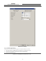
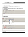
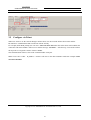
Model ATC-1000WF
WiFi Solutions for Serial Connections
User Manual
Updated on 2013/11/05
Tel: +86 755‐8345‐3318
Fax:+86 755‐8355‐5891
http://www.szatc.com
Important Announcement
The information contained in this document is the property of SHENZHEN ATC TECHNOLOGY CO.,LTD. and
is supplied for the sole purpose of the operation and maintenance of products of SHENZHEN ATC
TECHNOLOGY CO.,LTD. No part of this publication is to be used for any other purposes, and it is not to be
reproduced, copied, disclosed, transmitted, stored in a retrieval system, or translated into any human or computer
language, in any form, by any means, in whole or in part, without the prior express written consent of
SHENZHEN ATC TECHNOLOGY CO.,LTD.
Published by
SHENZHEN ATC TECHNOLOGY CO., LTD
Room 809, Taikang Building, Tairan Industrial & Trading Zone, Futian District, Shenzhen China
Latest product info: http://www.szatc.com
Phone: +86 755‐8345‐3318
Fax: +86 755‐8355‐5891
E-mail: [email protected]
[email protected]
Copyright © 2013 SHENZHEN ATC TECHNOLOGY CO., LTD. All rights reserved.
All other product names referenced herein are registered trademarks of their respective companies
Contents
1
Introduction .............................................................................................................................. 1
2
Hardware Setup......................................................................................................................... 2
2.1
3
LED Indicators................................................................................................................ 3
2.1.1
LINK LED............................................................................................................. 3
2.1.2
ACT LED .............................................................................................................. 3
2.1.3
PWR LED ............................................................................................................. 3
2.2
Installation Procedures .................................................................................................... 3
2.3
Power.............................................................................................................................. 4
Configuration............................................................................................................................ 5
3.1
Configuration Introduction .............................................................................................. 5
3.2
Configure via Tera-Term ................................................................................................. 5
3.2.1
3.3
Detail description for command ............................................................................. 6
Configure by Webpage .................................................................................................... 7
3.3.1
Login Authentication Page ..................................................................................... 7
3.3.2
Basic Page ............................................................................................................. 7
3.3.3
Advanced Page ...................................................................................................... 9
3.3.4
Security Page........................................................................................................10
3.3.5
WiFi Page .............................................................................................................11
3.3.6
WiFi Wiazrd Page.................................................................................................12
3.3.7
Status Page ...........................................................................................................15
3.4 Software Function Description ..........................................................................................15
3.5
3.4.1
Device Monitor Tool.............................................................................................15
3.4.2
Virtual Serial Port .................................................................................................21
Configure via Telnet .......................................................................................................22
I
User Manual
GPRS Solutions for Serial Connections
1
Introduction
ATC-1000WF wireless serial device servers give you an easy way to connect your RS-232/485/422 serial device
to WLAN.
The RS232 connection application has been used for a long time. RS232 cable has limitations in distance. WLAN
has become a worldwide standard protocol for wireless application. There are many application for using RS232
connection over WLAN,include POS,data capture,telemetry,PLC controllers,remote control,vending
machine,industrial control ,and others.The device that supports connection over WLAN is called as wireless to
Serial Server.
ATC-1000WF wireless serial device servers support automatic IP configuration protocols and manual
configuration via a handy web browser console.An external antenna increases the range of the wireless
connection.Users can position the adjustable antenna for maximum signal strength or even replace the antenna
with their own for additional flexibility and scalability.This feature is particularly useful when a serial device is
connected in a high interference area.As an added feature,a signal strength indicator is located on the front panel
to make it easier to troubleshoot connection problems.
ATC-1000WF wireless serial device servers ensure the compatibility of network software that uses a standard
network API by providing TCP Server Mode, TCP Client Mode, and UDP Mode. The Real COM/TTY drivers
allow software that works with COM/TTY ports to be set up to work over a TCP/IP network in no time. This
excellent feature preserves your software investment and lets you enjoy the benefits of networking your serial
devices instantly.
To make your management task easier, the ATC-1000WF provides additional features, such as password
authentication, IP filter, WEP support for 64-bit and 128-bit encryption, and SNMP support.
Packaging
Please check ones package contains the following items:
§
ATC-1000WF x
§
Power Adapter 9~24VDC x
§
Product CD containing configuration utility x 1
§
ATC-1000WF quick start guide x
§
Monopole Antenna (2dBi RP-SMA) x 1
1
1
1
1
User Manual
GPRS Solutions for Serial Connections
2
Hardware Setup
Copyright © 2013 SHENZHEN ATC TECHNOLOGY CO., LTD.
2
User Manual
GPRS Solutions for Serial Connections
2.1
LED Indicators
2.1.1 LINK LED
Message
Description
Off
Wi-Fi Disconnected
On
Wi-Fi Connected
Table 1. LINK LED Message
2.1.2
ACT LED
Message
Description
Off
No data transmit between serial port and RF
Blinking
Data transmit between serial port and RF
Table 2. ACT LED Message
2.1.3
PWR LED
Message
Description
On
Power on
Off
Power off
Table4. PWR LED Message
2.2
Installation Procedures
Installation of antenna:
Screw the SMA male pin of the antenna to the female SMA outlet of the ATC-1000WF tightly.
Copyright © 2013 SHENZHEN ATC TECHNOLOGY CO., LTD.
3
User Manual
GPRS Solutions for Serial Connections
Warning: The antenna should be screwed tightly, or the signal quality of antenna will be influenced!
Installation of cable:
Uses a RS232 or RS422 or RS485 data cable connect the ATC-1000WF to user’s device.
2.3
Power
The power range of ATC-1000WF is DC 9~24V.We recommend use to use the standard DC 9V/1A power
adapter.
Copyright © 2013 SHENZHEN ATC TECHNOLOGY CO., LTD.
4
User Manual
GPRS Solutions for Serial Connections
3
Configuration
Before configuration, we should connect the ATC-1000WF to a PC with a RS-232 cable as following.
3.1
Configuration Introduction
For ATC-1000WF you can configure via webpage or send command by Tera-Term.
3.2
Configure via Tera-Term
Default parameters of serial port are: 115200bps, 8bits, no parity, 1 stop bit, no flow control.
Firstly,configure Tera-Term with the default parameters,like following picture.
Run Tera-Term on the PC,and then enter “+++”.The interface like following will appear.
Copyright © 2013 SHENZHEN ATC TECHNOLOGY CO., LTD.
5
User Manual
GPRS Solutions for Serial Connections
Then input “help”,the all command will print in the window.Like below.
The commands can be classified into two functions, one is to execute command and the other is to set
configuration. The commands for setting configuration can be used in 2 ways: one is to display the current
settings when no argument is given and the other is to set the configuration with provided arguments.
3.2.1
Detail description for command
Following will introduce some commonly used commands.
Ø +++
When you power on ATC-1000WF,enter this command turn to CMD mode.
Ø AXCmd2Net
Enter this command, ATC-1000WF will return back to data transmit mode.
Ø help
Enter this command to get all command of this product.
Ø setnt <0 = Infra mode, 1 = Ad-hoc mode>
Copyright © 2013 SHENZHEN ATC TECHNOLOGY CO., LTD.
6
User Manual
GPRS Solutions for Serial Connections
This command can change the work mode of WLAN.
For example: setnt -- check current work mode
setnt 0 -- turn to Infra mode (AP)
Ø sisrvy
Enter this command to search available access point.
Ø jbss <ID in site-survey table>
Enter this command to access a point available. The ID number must be an index in the site survey result list.
Ø ipconfig
Use this command to check current network parameters of ATC-1000WF, such as IP address,subnet address and
gateway address.
Note: Every command should be send out with “<CR>” ---- the “Enter” key on keyboard.
3.3
Configure by Webpage
Here we will use Infra mode (AP) as example.And you also can use Ad-Hoc mode to do this,the webpage is
same. When access to a router by AP mode, the product will assign an IP address by router. For
example:192.168.1.100.
3.3.1 Login Authentication Page
Run the Internet Explorer,type the IP address into the address bar,like following.
When enter to this address,the following page will appear.
Default User Name: admin, Default User Name: admin.
The HTTP server will redirect to Basic page if the authentication is successful.
3.3.2 Basic Page
Copyright © 2013 SHENZHEN ATC TECHNOLOGY CO., LTD.
7
User Manual
GPRS Solutions for Serial Connections
On this page, the Client Destination Host Name/IP field can accept either host name or IP address format;for
example,you can enter “abnerliu.vicp.cc” or “192.168.1.200” in this field.
This page supports 4 command bottoms:
Ø
Apply : submits the current settings on this page to the device server.
Ø
Cancel: cancels the changed settings on this page.
Copyright © 2013 SHENZHEN ATC TECHNOLOGY CO., LTD.
8
User Manual
GPRS Solutions for Serial Connections
Ø
Restore_Default: restore the device server back to factory default setting.When click it,a warning dialog
will appear.You can click OK to continue operation or click Cancel to cancel the operation.
Ø
Reboot: restart the device server.
When clicking Apply or Reboot, a confirmation window will appear. User can click OK to continue the
operation, or click Cancel to cancel the operation.
3.3.3
Advanced Page
This page supports 3 firmware upgrade bottoms.Note that before user performs the firmware upgrade,one
should start TFTP server.
Ø Upgrade_Bootldr: upgrades the boot-loader firmware and then reboot the device server.
Ø Upgrade_MCPU: upgrades the MCPU firmware and then reboot the device server.
Copyright © 2013 SHENZHEN ATC TECHNOLOGY CO., LTD.
9
User Manual
GPRS Solutions for Serial Connections
Ø Upgrade_WCPU: upgrades the WCPU firmware and then reboot the device server.
User should enter correct TFTP server IP address and the firmware file name (without file path is fine) for
upgrade before clicking these bottoms.
When clicking Apply or any firmware upgrade button, a confirmation window will appear. User can press OK
to continue the operation, or press Cancel to cancel the operation.
The E-mail Server Address/IP field can accept host name or IP address format, for example, you can enter
“abnerliu.vicp.cc” or “1921.168.2.100”in this field.
The device server supports the DHCP server service and user can setup the settings of DHCP server and
press Apply to change the current settings.
3.3.4 Security Page
On this page, the Accessible IP Setting must be used with care. User should enter correct accessible IP address(s)
before enabling this function. The new configuration will take effect after the device server reboots.
Copyright © 2013 SHENZHEN ATC TECHNOLOGY CO., LTD.
10
User Manual
GPRS Solutions for Serial Connections
When clicking Apply, a confirmation window will appear. User can press OK to continue the operation, or
press Cancel to cancel the operation.
When clicking Logout at the top right corner of the page, the session will be logged out and redirected to the
login page.
3.3.5
WiFi Page
The page configures the WiFi settings of device server’s WiFi network. Note that the current value of WEP
Key Index 0~3 fields will be displayed according to Key Length field being selected, either 64 bits or 128 bits
(i.e. WEP-64 or WEP-128).
When clicking Apply, a confirmation window will appear. User can press OK to continue the operation, or
Copyright © 2013 SHENZHEN ATC TECHNOLOGY CO., LTD.
11
User Manual
GPRS Solutions for Serial Connections
press Cancel to cancel the operation.
3.3.6
WiFi Wiazrd Page
The WiFi Wizard is similar to WiFi page but provides a step by step procedure to help user to configure WiFi
network settings and avoid incorrect settings. The WiFi Wizard includes following 6 sub-pages:
Ø WiFi Link Settings sub-page
Ø Encryption Selection sub-page
Ø WiFi Network Advanced Settings sub-page
Ø The Wizard Complete Successfully sub-page
3.3.6.1
WiFi Link Settings sub-page
This sub-page provides basic configuration for device server’s WiFi network.
Copyright © 2013 SHENZHEN ATC TECHNOLOGY CO., LTD.
12
User Manual
GPRS Solutions for Serial Connections
3.3.6.2 Encryption Selection sub-page
This sub-page configures the encryption type that will be used.
3.3.6.3 WiFi Network Advanced Settings sub-page
This sub-page configures either WEP-64 or WEP-128 key settings, if WEP encryption is chosen for device
server’s WiFi network. The Key Index selects the active key to use among the 4 Key Indexes. Note that the
key length must be 10 characters for WEP 64 bits or 26 characters for WEP 128 bits.
Copyright © 2013 SHENZHEN ATC TECHNOLOGY CO., LTD.
13
User Manual
GPRS Solutions for Serial Connections
3.3.6.4 The Wizard Complete Successfully sub-page
This sub-page displays the new WiFi settings user has configured but not yet saved to ATC-1000WF device.
Now, user can review and confirm them.
Copyright © 2013 SHENZHEN ATC TECHNOLOGY CO., LTD.
14
User Manual
GPRS Solutions for Serial Connections
3.3.7 Status Page
This page displays the current status of ATC-1000WFdevice server with auto-refreshing in every 3 seconds.
3.4 Software Function Description
This section describes the detailed information of various software functions available, such as AXR2W
Configuration Utility.
3.4.1
Device Monitor Tool
This section describes the detailed functions of Device Monitor tool in AXR2W Configuration Utility.
3.4.1.1 Function Window
Copyright © 2013 SHENZHEN ATC TECHNOLOGY CO., LTD.
15
User Manual
GPRS Solutions for Serial Connections
The Device Management tool provides following functions:
Ø System Setting: configures the Search, Reboot, and Reset period.
Ø Search: searches for available AX220xx device(s) on the wireless LAN network.
Ø IP Search: searches the AX220xx device with a specified IP address.
Ø Device Setup: configures the settings of the selected AX220xx device.
Ø Web Browser: opens remote configuration web server of the selected AX220xx device.
Ø Reboot: restarts the selected AX220xx device.
Ø Restore: configures the selected AX220xx device back to factory default settings and restarts it.
Ø Firmware Upgrade: upgrades the firmware code of the selected AX220xx device.
3.4.1.2 Search Dialog
When click the search bottom,the search dialog will appear.
This function can support two ways to search device.One is UDP Multicast and UDP Broadcast.The default
setting is Broadcast.
3.4.1.2 IP Search Dialog
When clicking IP Search, the IP Search dialog will appear.
Enter the IP address of the device to search the device. E.g.:192.168.1.100
3.4.1.3
Device Setup Dialog
When clicking Device Setup, the Device Setup dialog will pop up with 4 tabs: Network Setting, Serial Port
Setting, WiFi Setting, and DHCP Server Setting.
Copyright © 2013 SHENZHEN ATC TECHNOLOGY CO., LTD.
16
User Manual
GPRS Solutions for Serial Connections
Network Setting
Copyright © 2013 SHENZHEN ATC TECHNOLOGY CO., LTD.
17
User Manual
GPRS Solutions for Serial Connections
Serial Port Setting
Copyright © 2013 SHENZHEN ATC TECHNOLOGY CO., LTD.
18
User Manual
GPRS Solutions for Serial Connections
Wifi Setting
Copyright © 2013 SHENZHEN ATC TECHNOLOGY CO., LTD.
19
User Manual
GPRS Solutions for Serial Connections
DHCP Server Setting
3.4.1.4 Firmware Upgrade Dialog
Note that before user performs the firmware upgrade, one should start TFTP Server tools first.
Ø
Ø
Ø
Select the target ATC-1000WF RS-232 to WiFi device from the Devices List.
Click Firmware Upgrade to bring up the Firmware Upgrade dialog.
Choose the firmware file type.
Copyright © 2013 SHENZHEN ATC TECHNOLOGY CO., LTD.
20
User Manual
GPRS Solutions for Serial Connections
Ø
Ø
Ø
Input a correct ATC-1000WF RS-232 to WiFi firmware file name.
Input the TFTP server IP address.
Click Upgrade Firmware to start upgrading the new ATC-1000WF firmware code.
3.4.2
Virtual Serial Port
This section describes the detailed functions of Virtual Serial Port tool in AXR2W Configuration Utility.
3.4.2.1 Function Window
3.4.2.2 Add a Virtual Port
Step 1: Click Add to add a Virtual Serial Port. Below example shows a COM9 Virtual Serial Port being added.
Step2:
Step3:
Select the added Serial Port from the Ports List.And then click setting.
Select Protocol and work mode,enter the IP address and port number of ATC-1000WF which you want to make a Virtual
Port.Then press OK.
Copyright © 2013 SHENZHEN ATC TECHNOLOGY CO., LTD.
21
User Manual
GPRS Solutions for Serial Connections
3.5
Configure via Telnet
When user wants to use the console through a Telnet client, user must run the Telnet client on PC and the
DS must have established the WiFi connection with PC already.
For example,under DOS prompt,user can enter “telnet 192.168.1.100”.Then the Telnet client will establish the
connection with ATC-100WF’s Telnet server and the message “username: “ will show up, if successful. Follow
the steps above to login the console of ATC-1000WF.
The command under telnet is same to the command under serial port.
Note: if user enter “telnet
1921.68.1.100 5000”.
IP_Address PortNo.”will enter to the data transmitter mode.For example:”telnet
Copyright © 2013 SHENZHEN ATC TECHNOLOGY CO., LTD.
22
User Manual
GPRS Solutions for Serial Connections
Room809, Taikang Building,Tairan Industrial&Trading
ZoneFutian District, Shenzhen,P.R China
Tel: +86 755‐8345‐3318
Fax:+86 755‐8355‐5891
E-mail:mailto:[email protected]
WEB:http://www.szatc.com
Copyright © 2013 SHENZHEN ATC TECHNOLOGY CO., LTD.
23