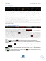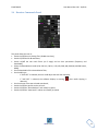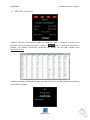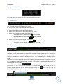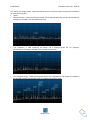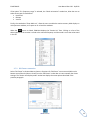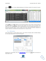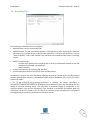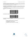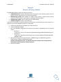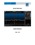
1
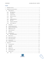
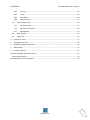
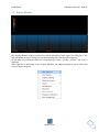
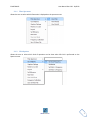
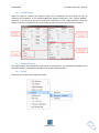
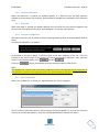
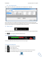
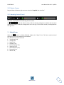
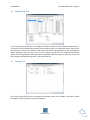
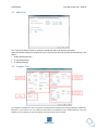
ELAD FDM-SW1 USER MANUAL ELAD FDM-S1 User Manual Rev 2.02 10/2012 Index 1 FDM-SW1 Overview .............................................................................................................................. 4 2 Graphical User Interface (GUI) .............................................................................................................. 5 2.1 Display Window ............................................................................................................................ 6 2.1.1 Filter Spectrum ...................................................................................................................... 7 2.1.2 Click Options ......................................................................................................................... 7 2.1.3 Graphics Setup ...................................................................................................................... 8 2.1.4 Marker on screen .................................................................................................................. 8 2.1.5 Layout.................................................................................................................................... 8 2.1.6 Set/Reset Reference ............................................................................................................. 9 2.1.7 Max Hold ............................................................................................................................... 9 2.1.8 Frequency Calibration ........................................................................................................... 9 2.1.9 Save To Mem File .................................................................................................................. 9 2.2 Tuning Bars.................................................................................................................................. 10 2.3 Tuning Commands Panel ............................................................................................................ 10 2.4 Receiver Commands Panel.......................................................................................................... 11 2.5 DRM/RDS Info Panel ................................................................................................................... 12 2.6 System Info Panel........................................................................................................................ 13 2.7 Status Bar .................................................................................................................................... 13 2.8 Player/Recorder .......................................................................................................................... 13 2.8.1 3 Recording Scheduler ........................................................................................................... 14 2.9 Mute Control ............................................................................................................................... 14 2.10 Signal Control Display ................................................................................................................. 14 2.11 Main Setting Buttons .................................................................................................................. 14 2.12 Resize Corner .............................................................................................................................. 15 2.13 Omnirig Control Panel................................................................................................................. 15 Setup Form .......................................................................................................................................... 15 3.1 Tuning Step Tab .......................................................................................................................... 16 3.2 Tuning Tab................................................................................................................................... 16 3.3 Audio Tab .................................................................................................................................... 17 3.4 Graphics Tab ............................................................................................................................... 17 3.5 Demod Settings Tab .................................................................................................................... 18 3.6 Advanced Tab.............................................................................................................................. 18 3.6.1 CAT ...................................................................................................................................... 19 www.eladit.com 2 ELAD FDM-S1 User Manual Rev 2.02 10/2012 3.6.2 Omnirig................................................................................................................................ 19 3.6.3 Tmate .................................................................................................................................. 19 3.6.4 Panadapter .......................................................................................................................... 19 3.6.5 Downconverter ................................................................................................................... 20 3.7 Station Memory Tab ................................................................................................................... 20 3.7.1 Xml memory file .................................................................................................................. 21 3.7.2 DX Cluster connection ......................................................................................................... 23 3.7.3 EIBI Database ...................................................................................................................... 24 3.8 Recording Tab ............................................................................................................................. 25 3.9 About Tab .................................................................................................................................... 26 4 IF Spectrum Form ................................................................................................................................ 27 5 Audio Spectrum Form ......................................................................................................................... 29 6 FDM-SW1 Hardware Setup Form........................................................................................................ 30 7 Offline Mode ....................................................................................................................................... 31 8 Connect to Server ............................................................................................................................... 31 Annex A ELAD FDM-SW1 CAT Protocol ....................................................................................................... 32 Command Description ............................................................................................................................ 33 Annex B Restore to Factory Default............................................................................................................ 36 www.eladit.com 3 ELAD FDM-S1 User Manual Rev 2.02 10/2012 1 FDM-SW1 Overview Elad FDM-SW1 is a SDR (Software Defined Radio) software that is intended to be used with the Elad FDM-Sx Receiver family. Please check out the latest update of this document at www.eladit.com. Note: this manual is based on FDM-SW1 ver. 3.04. www.eladit.com 4 ELAD FDM-S1 User Manual Rev 2.02 10/2012 2 Graphical User Interface (GUI) The screen shot below shows the main screen (the cockpit) of the Graphical User Interface. The GUI consists of 12 parts: 1. Display Window; 2. Tuning Bars; 3. Tuning Commands Panel; 4. Receiver Commands Panel; 5. DRM/RDS Info Panel; 6. System Info Panel; 7. Status Bar; 8. Player/Recorder; 9. Mute Control; 10. Signal Control Display; 11. Main Setting Buttons; 12. Resize Corner. 13. Omnirig control panel www.eladit.com 5 ELAD FDM-S1 User Manual Rev 2.02 10/2012 2.1 Display Window The “Display Window” displays the Spectrum and the Waterfall of input signal. The sliding bar on the right side allows the user to change the area portions assigned to the two types of graphics. On the lower part, information about the current setting of “Span”, “FFT Res”, “kHz/div” and “AVG” is displayed. When right-click is performed on the “Display Window” the software displays a pop-up menu that contains advanced options. www.eladit.com 6 ELAD FDM-S1 2.1.1 User Manual Rev 2.02 10/2012 Filter Spectrum Allows the user to select which information is displayed on the spectrum area. 2.1.2 Click Options Allows the user to select which kind of operation can be done when left-click is performed on the Spectrum area. www.eladit.com 7 ELAD FDM-S1 2.1.3 User Manual Rev 2.02 10/2012 Graphics Setup When this option is selected, the “Graphics Setup” form is displayed. This form allows the user to configure the parameters of the Spectrum/Waterfall graphics displayed in the “Display Window”. Moreover, in this form the user can customize the visualization of the “Audio Spectrum” form (see Chapter 5) and the “IF Spectrum” form (see Chapter 4) and the S-meter rise and fall time constants. 2.1.4 Marker on screen This option enables the visualization of the marker on the Spectrum. The amplitude value (dBm) of the selected frequency is displayed on top-right corner of the “Display Window”. 2.1.5 Layout Allows the user to select the visualization mode. www.eladit.com 8 ELAD FDM-S1 2.1.6 User Manual Rev 2.02 10/2012 Set/Reset Reference When “Set Reference” is selected, the software displays as a reference curve the input spectrum available at the moment of the selection. “Reset Reference” disables the visualization of the reference curve. 2.1.7 Max Hold When “Max Hold” is selected, the software displays the max hold of the input spectrum together with the real-time input spectrum trace. Click “Max Hold Reset” to reset the max hold trace. 2.1.8 Frequency Calibration This option allows the user to modify the factory sampling frequency offset of the Elad FDM-Sx Receiver family. Normally this operation is not needed. As described in the pop-up above, a reference signal at the same frequency of the L.O., has to be provided at the antenna input of the receiver to perform the frequency calibration. Then, place the marker on the reference (peak), press Clicking on and then . button, the software resets the sampling frequency offset to zero. NOTE: This operation will cause the loss of the factory calibration. Perform this operation only if you are sure to accomplish the operation in the right way and to use a precise frequency reference. 2.1.9 Save To Mem File When “Save To Mem File” is clicked, the “Add to Memory File” Form is displayed. This form allow to add a new station in station memory file (See paragraph 3.7). The user can select the memory file and save the frequency, name and a default demodulation mode for the station. www.eladit.com 9 ELAD FDM-S1 User Manual Rev 2.02 10/2012 2.2 Tuning Bars These innovative tuning bars (Patent Pending) allow the user to perform fast tuning over the whole receiver bandwidth. Each bar is characterized by different frequency spans. By performing drag-anddrop over the different bars, the user can easily select the desired frequency using the lower bar to select the frequency band, the middle bar to make a rough tuning and the higher bar to do fine positioning. The span of the higher bar corresponds to the frequency range of the spectrum, and can be modified using the zoom buttons in the “Tuning Commands Panel”. The frequency step of the higher bar (displayed in the “Tuning Commands Panel”) can be changed using the ← → arrows on the PC keyboard, while ↑ ↓ keys increase or decrease the tuning frequency by one step respectively (see Chapter 3.2 for keyboard shortcut configuration). The yellow segment on the middle bar represents the portion of the spectrum displayed by the software in the “Display Window”. 2.3 Tuning Commands Panel The main function of this panel is to display the tuning frequency. Double click on the frequency display or press space bar ( ) to insert manually the desired value using the PC keyboard (Note: “+” key allow to insert “000”). If the “LOCK TO CF” button is selected ( ) the tuning frequency corresponds to the center frequency of the Spectrum (that is the L.O. frequency), otherwise it’s possible to select different demodulation frequencies by clicking on the desired point on the Spectrum/Waterfall or using the mouse scroll wheel over the Spectrum/Waterfall area. If the “LOCK ABS” button is selected ( ) the tuning frequency remains constant even if the local oscillator frequency is changed (until the tuning frequency falls within the selected frequency span; otherwise the tuning frequency will be set according to the frequency span limits). If the “LOCK” button is selected ( ), all the settings except the volume controls are disabled. Clicking on button the software forces the L.O. frequency to be equal to the current demodulation frequency. Use the “SNAP” button ( ) to enable/disable the rounding of the tuning frequency at multiples of the frequency step. Buttons implement “zoom in”, “zoom out” and “zoom reset” respectively. Use the arrows that appear on the “Display Window” when zoom function is active to move left/right the visualization. Moreover, the “Tuning Commands Panel” shows the label when a Tmate is connected and the label when the CAT protocol is enabled. www.eladit.com 10 ELAD FDM-S1 User Manual Rev 2.02 10/2012 2.4 Receiver Commands Panel This panel allows the user to: Switch On/Off the anti-aliasing filter (30 MHz Low Pass); Switch On/Off the 20 dB attenuator; Switch On/Off the two notch filters (at IF stage) and set their parameters (frequency and bandwidth); Select the demodulation mode (CW, CW SH+, CW SH-, USB, LSB, DSB, AM, SAM,FM, WB FM Stereo, DRM); Set the bandwidth of the demodulation filter; Set the AGC type - if “AGC OFF” is selected, the user could adjust the AGC Gain manually; - if “AGC OFF” is selected, the software displays a warning detected; Set the volume of the two selected soundcards; Switch On/Off the squelch and set its level; Switch On/Off the “Noise Reducer” and modify its speed; Switch On/Off the “Auto Notch” reducer and modify its speed; www.eladit.com when audio clipping is 11 ELAD FDM-S1 User Manual Rev 2.02 10/2012 2.5 DRM/RDS Info Panel If DRM is selected as demodulation mode, the “DRM Info Panel” is activated. It displays some information about the DRM transmission. Clicking on button, if an internet connection is available, the software automatically downloads and displays the last DRM schedule from ftp://216.92.35.131. If WB FM is selected as demodulation mode, the “RDS Info Panel” is activated. It displays the decoding of some RDS information. www.eladit.com 12 ELAD FDM-S1 User Manual Rev 2.02 10/2012 2.6 System Info Panel This panel displays the system time (UTC and local) and the CPU usage. 2.7 Status Bar The “Status Bar” displays the following information: Serial number of the connected Elad FDM-Sx Receiver; L.O. Frequency; Selected demodulation mode and filter bandwidth; Status of the “Noise Reducer” and “Auto Notch” (On or Off); Status of the “Panadapter Mode” (see Chapter 3.6) - If “Panadapter Mode” is activated, the label is showed; - If AOR AR8600 Control is activated the label is showed; - If “Swap I/Q” option is selected, the label is showed; Status of the “Downconverter Mode” (see Chapter 3.6) - If “Downconverter Mode” is activated, the label is showed; - If “Swap I/Q” option is selected, the label is showed; 2.8 Player/Recorder FDM-SW1 embeds an advanced player/recorder. When the recorder is activated, the RF input signal or the audio output signal is stored in a .wav file (see Chapter 3.8). Some information regarding the settings used during the recording (file creation date, L.O. frequency, demodulation frequency, demodulation mode, filter bandwidth, etc.) is stored in the file’s header. When the file is played, the stored information is loaded by the software. When the playback is finished, last demodulation settings (demodulation frequency, demodulation mode and filter bandwidth) are stored again in the .wav header. Six button function are available (Loop, A, B, Rec, Play/Pause, Stop). After placing “A” and “B” (when the reproduction is stopped), user can create a new file with the samples included between the two markers by right-clicking the label. www.eladit.com button and then click the 13 ELAD FDM-S1 2.8.1 User Manual Rev 2.02 10/2012 Recording Scheduler When a right-click is performed on the Rec button, the “Rec Option Form" is displayed This form allow the user to schedule the recording of the input spectrum or the audio output signal. The user can set the start and stop time of recording (UTC Time or Local Time), the demodulation mode, the local oscillator frequency, the tuning frequency and the file name prefix. 2.9 Mute Control In this area, the DFM-SW1 software shows the name of the selected primary sound card (Sound Card 1). Use the button to activate or deactivate the Mute function. 2.10 Signal Control Display In this area, the DFM-SW1 software displays the level of the input signal. 2.11 Main Setting Buttons Button switches on/off the demodulation. Button opens the “Setup” form. Button opens the “Station List” form. Button opens the FDM-SW1 Guide. Refer this guide to know useful shortcut key functions. Button opens the Windows dialog box to allows the user to select the file to play. www.eladit.com 14 ELAD FDM-S1 User Manual Rev 2.02 10/2012 2.12 Resize Corner Drag-and-drop the bottom-right corner to resize the “Graphical User Interface”. 2.13 Omnirig Control Panel This panel is displayed when the Omnirig control is active. The check box allow to show / hide the Omnirig configuration window and the others checkboxes allow to enable the management of the two rigs. In the others controls, are displayed the two rigs status. 3 Setup Form When the button is clicked, FDM-SW1 displays the “Setup” form. This form contains several settings that control the behavior of the software. The “Setup” form consists of 9 tabs: 1 “Tuning Step” tab; 2 “Tuning” tab; 3 “Audio” tab; 4 “Graphics” tab; 5 “Demod Settings” tab; 6 “Advanced” tab; 7 “Station Memory” tab; 8 “Recording” tab; 9 “About” tab; www.eladit.com 15 ELAD FDM-S1 User Manual Rev 2.02 10/2012 3.1 Tuning Step Tab In the “Tuning Step” tab the user can configure the frequency steps that the software sets when the ← → arrows on the PC keyboard are pressed; these frequency steps are configurable under “Step Preset” area. Moreover, the user can compile a table containing custom setting (frequency step, demodulation mode, attenuator, low pass filter, Ext I/O, down converter mode) that the software automatically applies if the tuning frequency falls within the user-defined frequency ranges: to make this, check “Use tuning frequency related settings table” on the top of the tab. 3.2 Tuning Tab The “Tuning” tab allows the user to customize the frequency span of the “Middle” and “Band” (lower) tuning bars and the keyboard shortcuts configuration. www.eladit.com 16 ELAD FDM-S1 User Manual Rev 2.02 10/2012 3.3 Audio Tab The “Tuning” tab allows the user to select the soundcards and to set the AGC parameters. When the second soundcard is enabled, the user can select the data type that will be reproduced on this device: Audio (48 kSamples/sec) IF (192 kSample/sec) IF (48 kSample/sec) 3.4 Graphics Tab The “Graphics” tab allows the user to customize several parameters related to the “Display Window” visualization. Moreover, in this tab the user can enable and customize the visualization of the “Audio Spectrum” form (see Chapter 5), the “IF Spectrum” form (see Chapter 4) and the S-meter time constants. www.eladit.com 17 ELAD FDM-S1 User Manual Rev 2.02 10/2012 3.5 Demod Settings Tab The “Demod Settings” tab allows the user to customize several parameters related to the demodulation algorithms. In the “Filter Bw Settings” panel, the software summarizes the current values of the filter’s bandwidth for each type of demodulation mode (a default value is displayed as suggestion). 3.6 Advanced Tab In this tab, the user can select the advanced options of the software. If the checkbox is selected (default), the software operates in “Receiver Mode” and limits the maximum tunable frequency at the Nyquist frequency (half of the ADC sampling rate). If the checkbox is deselected, the software operates in “Sampler Mode” and unlocks the limitation. If the “Sampler Mode” is activated, the user can force the software to highlight the multiples of the Nyquist frequency on the Spectrum by checking the checkbox. www.eladit.com 18 ELAD FDM-S1 User Manual Rev 2.02 10/2012 Checking the checkbox, the “FDM-SW1 Hardware Setup” form is loaded at software startup (see Chapter 6). To enable the DC offset correction feature of the ADC, check the checkbox; this option removes ADC offset at 0 Hz. 3.6.1 CAT When the CAT control is active, the “Tuning Commands Panel” displays the label. In the “CAT Panel” the user can configure the serial communication settings. The FDM-SW1 implements the command set of the “Yaesu Ft897” transceiver. 3.6.2 Omnirig When the is checked, the FDM-SW1 software can control two transceivers using the Omni-Rig technology. Please go to website http://dxatlas.com/OmniRig/ for more information about Omni-Rig. Note: Omnirig must be installed in your PC. 3.6.3 Tmate If a Tmate is connected, the “Tmate Panel” is activated. In this panel, the user can choose among the proposed configurations of Tmate’s button functions. When the Tmate control is active, the “Tuning Commands Panel” displays the following labels: if ; if or 3.6.4 Panadapter If “Panadapter Mode” is activated (the “Status Bar” displays the label), the user can configure the IF frequency for the different demodulation modes and the amplitude offset that allows the right visualization. Moreover, the spectrum flip around L.O. frequency can be enabled by check “Swap I/Q” www.eladit.com 19 ELAD FDM-S1 User Manual Rev 2.02 10/2012 option (the “Status Bar” displays the label). This configuration parameters can be saved/loaded using the buttons and respectively. Enabling the AOR AR8600 Control (the “Status Bar” displays the label), the SW can directly control this Radio through serial communication. 3.6.5 Downconverter If “Downconverter Mode” is activated (the “Status Bar” displays the label), the user can configure the IF frequency shift of the downconverter and the amplitude offset that allows the right visualization. Moreover, the spectrum flip around L.O. frequency can be enabled by check “Swap I/Q” option (the “Status Bar” displays the label). 3.7 Station Memory Tab In the FDM-SW1, three types of memory source are available: Xml memory file; DX Cluster Connection; EIBI Database. www.eladit.com 20 ELAD FDM-S1 3.7.1 User Manual Rev 2.02 10/2012 Xml memory file Select “File” as Station Memory Source. Press button to create a new memory file. When a new file is created or when button is pressed, FDM-SW1 visualizes an “Edit” form (represented in the figure below): user can add or delete stations from the editor to create or change a memory file. Press or button to load or unload a memory file respectively (more than one memory file can be loaded at the same time). The table on the right side of the tab displays all the stations that are stored in the selected memory files. www.eladit.com 21 ELAD FDM-S1 User Manual Rev 2.02 10/2012 The “Station info display mode” combo-box allows the user to choose 4 types of memories visualization on the Spectrum graphic: “None”; “Mouse position”: a label containing the station info is displayed when the mouse is positioned over a frequency included in the selected memory files; “L.O. Frequency”: a label containing the station info is displayed when the L.O. frequency corresponds to a frequency included in the selected memory files; “If in frequency range”: a label containing the station info is displayed for each frequency included in the selected memory files that falls within the Spectrum frequency range. www.eladit.com 22 ELAD FDM-S1 User Manual Rev 2.02 10/2012 If the option “If in frequency range” is selected, the “Labels orientation” combo-box, allow the user to select three types of visualization: Horizontal Oblique Vertical Finally, the combo-box “Show labels on”, allow the user to enable the station memory label display on main spectrum window, on IF spectrum or on both the windows. When the button is clicked, FDM-SW1 displays the “Station List” form. Clicking on a line of the table implies that the receiver is tuned at the selected frequency and the mode is set at the value saved in the file. 3.7.2 DX Cluster connection Select “DX Cluster” as Station Memory Source: all options for “DXCluster” source are available on the bottom area of the tab. Select a cluster from the “DXCluster” combo-box or insert manually the cluster settings. The “Station info display mode” combo-box displays the same options described in the previous paragraph. www.eladit.com 23 ELAD FDM-S1 When the form. User Manual Rev 2.02 10/2012 button is clicked, FDM-SW1 displays the “DX Cluster Interface” form and the “Contacts” Press or button of the “DX Cluster Interface” form to open or close the link with the Cluster, and use to send the string entered in the “Send” area. The “Contacts” form displays the users connected to the cluster. Double-clicking on a line of the table implies that the L.O. is tuned at the selected frequency. Use the “Show Log UTC” and “Show Expire Timeout” checkboxes to enable or disable the visualization of this information in the “Contacts” form. 3.7.3 EIBI Database Select “EIBI Database” as Station Memory Source. The “Station info display mode” combobox displays the same options described in the previous paragraphs. Download the CSV database file from www.eibispace.de. Click the downloaded .csf file. www.eladit.com button and select the 24 ELAD FDM-S1 User Manual Rev 2.02 10/2012 3.8 Recording Tab The “Recording” tab allows the user to configure: default directory for the recorded .wav files; default filename. The SW automatically appends to the filename a prefix containing the date-time information (yyyy-mm-dd-hh-mm-ss) plus the data type (RF for “Full Span Input Spectrum” or AF for “Audio Frequency”) and a suffix “RecXXX” that represents the incremental index within a recording section; default recording mode: - Full Span Input Spectrum (the sampling rate of the RF I/Q datastream depends on the HW configuration Dll loaded; see Chapter 6); - Audio Frequency; maximum allowed size for each recorded .wav files; maximum allowed number of .wav file for each recording session. As explained in chapter 2.8, some information regarding the settings used during the recording and the playback (demodulation frequency, demodulation mode and filter bandwidth) of a .wav file is stored is stored in its header. If the checkbox is checked, the stored information is automatically loaded by the software at the beginning of the playback of every file even though the files belong to the same recording session. This may cause an unwanted change of configuration in the transition between a file and the subsequent. If the checkbox is unchecked, the software loads the information stored in the header of the first file of the recording session and keeps this configuration unchanged until the end of the reproduction of the whole session. www.eladit.com 25 ELAD FDM-S1 User Manual Rev 2.02 10/2012 3.9 About Tab The “About” tab displays useful information about Software and Hardware. www.eladit.com 26 ELAD FDM-S1 User Manual Rev 2.02 10/2012 4 IF Spectrum Form If the checkbox of the “Graphics” tab is selected (see Chapter 3.4), the “IF Spectrum” form is automatically loaded when the button is pressed. This form displays the Spectrum/Waterfall of the IF frequency of the software. The frequency span is set to 192 kHz when the “WB FM” demodulation mode is selected, 48 kHz for the other modes. The user can select to visualize the Spectrum/Waterfall of the IF signal “Before Demod Filter ” or “After Demod Filter”. To zoom in/out the area of the tuning frequency, click on the / button. To zoom a desired area, press the “Shift” button of the keyboard while operating the drag-and-drop action over the Spectrum. Use the arrows when zoom function is active to move left/right the visualization and click the button to reset the zoom. User can perform three types of click function: set tuning to the selected frequency if is selected; set “Marker 1” if is selected (Note: the label is green ( ) when the “Marker 1” is enabled while is green and underlined ( ) when the click function is active); set “Marker 2” if is selected (Note: the label is cyan ( ) when the “Marker 2” is enabled while is cyan and underlined ( ) when the click function is active); If both markers are enabled, user can activate the function that displays the frequency and amplitude difference between the markers. www.eladit.com 27 ELAD FDM-S1 User Manual Rev 2.02 10/2012 Drag-and-drop the bottom-right corner to resize the “IF Spectrum” form. www.eladit.com 28 ELAD FDM-S1 User Manual Rev 2.02 10/2012 5 Audio Spectrum Form If the checkbox of the “Graphics” tab is selected (see Chapter 3.4), the “Audio Spectrum” form is automatically loaded when the button is pressed. Furthermore, this form is loaded by default when the player is active and the data type of the reproduced .wav file is “Audio Frequency” (see Chapter 3.8). The frequency span is set to 16 KHz for all demodulation modes. To zoom a desired area, press the “Shift” button of the keyboard while operating the drag-and-drop action over the Spectrum. Use the arrows when zoom function is active to move left/right the visualization and click the button to reset the zoom. In CW, CW SH+, CW SH-, USB, LSB, AM, FM, SYNC AM and DSB mode an audio filter is inserted at the end of the demodulation chain (audio filter is omitted in WB FM and DRM demodulation). This filter is represented by the green area drawn over the audio Spectrum. User can modify the bandwidth of the audio filter by drag-and-drop the borders of this area (Note: the higher frequency of the audio filter is limited to the bandwidth of the demodulation filter). Drag-and-drop the bottom-right corner to resize the “Audio Spectrum” form. www.eladit.com 29 ELAD FDM-S1 User Manual Rev 2.02 10/2012 6 FDM-SW1 Hardware Setup Form If the option of the “Advanced” tab is selected, the “FDM-SW1 Hardware Setup” form is loaded at software startup (see Chapter 3.6). Press button to start the FDM-SW1. Press button to start the FDM-SW1 in “OFFLINE Mode” (see Chapter 7). Since the FDM-SW1 is a general purpose software that works with the entire FDM-Sx Receiver family, the hardware configuration corresponding to the connected HW has to be selected. This operation is accomplished by clicking the button: a Windows dialog box is opened to allow the user to select the hardware configuration file (named ExtIO_ELAD_FDMSx_yyy.dll) The previous figure shows a directory containing five configuration Dlls for the FDM-S1 device. The filename code is explained in the following figure. NOTE: Please check out the latest update of your hardware related .dll file at www.eladit.com. www.eladit.com 30 ELAD FDM-S1 User Manual Rev 2.02 10/2012 7 Offline Mode If the button of the “FDM-SW1 Hardware Setup” form is pressed, FDM-SW1 starts in “OFFLINE Mode”. In this case, no connection with the hardware is established and only the playback of recorded files is available. 8 Connect to Server Press the button to connect the software to a remote FDM-Sx device through a server software (at the moment the server software is under development). www.eladit.com 31 ELAD FDM-S1 User Manual Rev 2.02 10/2012 Annex A ELAD FDM-SW1 CAT Protocol The FMD-SW1 implements a subset of the CAT commands of the Yaesu FT-897 transceiver. The parameters of the serial port are listed in the following table. Baud rate Data Size Parity Start Bits Stop Bits 38400 8 None 1 2 The command sent to FDMSW1 consists of 5 bytes and is structured as follows: FDM-SW1 software implements the following commands derived from the command set of FT-897: Command Description Data 1 Data 2 Data 3 Data 4 Command Set LO Frequency 100/10MHz 1MHz/100kHz 10/1kHz 100/10Hz 0x01 Set operating mode Mode Byte X X X 0x07 Read Receiver Status X X X X 0xE7 Read Frequency and mode X X X X 0x03 Read EE prom Data Address MSB Address LSB X X 0xBB Read TX Metering X X X X 0xBD Read Transmitter status X X X X 0xF7 Set PTT ON X X X X 0x08 Set PTT Off X X X X 0x88 www.eladit.com Remarks This commands sets the current frequency (see following command description) See following command description This command returns one byte containing receiver status (see following command description) This command returns five bytes (see following command description) This command causes two bytes of EEPROM data to be returned, beginning with the address in data bytes 1 and 2. (Approximately 6.25k of EEPROM data may be accessed - see following command description) This command returns one byte (00) when in receive. When in transmit, this command returns two bytes (in BCD format) indicating Forward power, VSWR, ALC, and Modulation. This command returns one byte containing transmitter status (see following command description) This "keys" the FT-817. In CW, this sets the radio to transmit mode, but does key the transmitter. Keying and unkeying the PTT line will cancel the transmit mode (i.e. put it back into receive.) This command returns 00 if the '817 was unkeyed, and F0 if already keyed. This command puts the FT-817 into receive mode. This command returns 00 if the '817 was keyed, and F0 if already unkeyed. 32 ELAD FDM-S1 User Manual Rev 2.02 10/2012 Command Description Command 0x01 - Set local oscillator frequency: the local oscillator frequency is set by the transmission of 4 Binary Coded Decimal (BCD) bytes. For example, to set the frequency at 435.12345 MHz the bytes to be sent are: [43][51][23][45] followed by the byte command [01]. The command returns 1 byte set to [00]. Command 0x03 - Read local oscillator frequency and mode: this command returns 5 bytes. The first four bytes contain the local oscillator frequency in the same format of the command 0x01 (4 BCD bytes), while the last byte contains the operating mode encoded as follows: Mode LSB USB CW, CW SH+, CW SHAM, SYNC AM FM, WB FM DRM Value 0x00 0x01 0x02 0x04 0x06 0x07 Command 0x07 - Set operation mode: the first byte contains the operating mode that is encoded as follows: Mode LSB USB CW AM WB FM FM Value 0x00 0x01 0x02 0x04 0x08 0x88 The command returns 1 byte set to [00]. Command 0xBB - Read EEPROM Data: this command returns 2 bytes. To simulate the behavior of the FT-897, the software replies to “EEprom read” request as follows Address 0x006A 0x00A9 0x006B 0x008C 0x00A8 0x008E Data 1 0xC4 0x00 0x20 0x00 0x00 0x40 Data 2 0x20 0x05 0x59 0x00 0x18 0x00 For example, if the software receive the command [00] [6A] [00] [00] [BB] the answer must be [C4] [20]. Command 0xBD - Read TX Metering: This command returns 1 byte set to [00] when receive mode is enabled, while it returns 2 byte set to [00] [00] when transmit mode is enabled. Command 0xE7 - Read Receiver Status: This command returns 1 byte. The 4 least significant bits indicate the current reading of S-METER. Some examples are reported in the following table www.eladit.com 33 ELAD FDM-S1 User Manual Rev 2.02 10/2012 Retuned Byte 0x00 0x04 0x09 0x0A 0x0B 0x0F S-METER S0 S4 S9 S9+10 S9+20 S9+60 Command 0xF7 - Read Transmitter Status: This command returns 1 byte. If “keyed” the byte is set to [7f] otherwise [ff]. In addition to the controls derived from the command set of FT-897, the CAT protocol include specific commands for the FDM-SW1: Command Description Set operating mode SW1 Read Tuning Frequency and mode Data 1 Data 2 Data 3 Data 4 Command Remarks Mode Byte X X X 0xC7 See following command description X X X X 0xC8 Set Tuning Frequency 100/10MHz 1MHz/100kHz 10/1kHz 100/10Hz 0xC9 Read Locked Mode X Locked Mode Byte X X X 0xCA This command returns five bytes (see following command description) This commands sets the current frequency (see following command description) See following command description X X X 0xCB See following command description X X X X 0xCF This command returns 10 bytes containing the FDM-SW1 status. (See following command description) Set Locked Mode Read FDM-SW1 Status Command 0xC7 - Set operating mode SW1: the first byte contains the operating mode that is encoded as follows: Mode CW CW SH+ CW SHUSB LSB AM FM DRM WBFM SYNC AM DSB Value 0x00 0x01 0x02 0x03 0x04 0x05 0x06 0x07 0x08 0x09 0x0A The command returns 1 byte set to [00]. www.eladit.com 34 ELAD FDM-S1 User Manual Rev 2.02 10/2012 Command 0xC8 - Read tuning frequency and mode: this command returns 5 bytes. The first four bytes contain the tuning frequency in the same format of the command 0x01 (4 BCD bytes), while the last byte contains the operating mode encoded as in command 0xC7. Command 0xC9 – Set Tuning frequency: the tuning frequency is set by the transmission of 4 Binary Coded Decimal (BCD) bytes For example, to set the frequency at 435.12345 MHz the bytes to be sent are: [43][51][23][45] followed by the byte command [C9]. The command returns 1 byte set to [00]. Command 0xCA – Read Locked Mode: this command returns 1 byte containing the receiver locked status Mode Unlocked Locked to CF Locked ABS LOCK Value 0x00 0x01 0x02 0x03 Command 0xCB – Set Locked Mode: this command returns 1 byte. Mode Unlocked Locked to CF Locked ABS Value 0x00 0x01 0x02 Command 0xCF - Read Global Status FDMSW1: this command returns 10 bytes containing the status of the FDM-SW1 Byte 0: Locked Mode (encoded as in command 0xCA) Byte 1 – Byte 4: LO Frequency (4 BCD) Byte 5 –Byte 8: Tuning frequency (4BCD) Byte 9: Operating mode (encoded as in command 0xC7) www.eladit.com 35 ELAD FDM-S1 User Manual Rev 2.02 10/2012 Annex B Restore to Factory Default The FDM-SW1 software settings are stored in some files: FDMSW1MainSetup: contains FDM-SW1 general settings like main windows position and size, graphics settings, default directory for save the recordings … FDMS1Settings_XXXXX (where XXXXX is the FDM-Sx serial number): contains specific receiver settings like Tune Frequency, LO Frequency, operating mode, filter BW etc… FDMS1Settings_Offline: specific settings for the “Offline Mode” FDMDS1Config.xml: frequency related settings If the files are corrupted or contains invalid data, the software can stop working correctly. However it is possible to restore the FDM-SW1 software in a stable state. Enable the visualization of the hidden files, folder and drives Close the FDM-SW1 Software Open the FDM-SW1 configuration file directory: the location is depending from the operating system: o Windows 7: “Local Drive”:\Users\”Your username”\AppData\Roaming\ELAD\ELAD FDMSW1\1.0.0.0 o Windows XP: “Local Drive”:\Documents and Settings\”Your username”\Application Data\ELAD\ELAD FDMSW1\1.0.0.0 Move the following files in another directory: FDMDS1Config.xml, FDMS1Settings_Offline, FDMS1Settings_XXXXX and FDMSW1MainSetup. Attention: by moving these files, you will lost all the user settings as last tuning frequency, demodulation mode, frequency related settings etc… Restart the software www.eladit.com 36