1
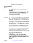
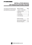
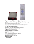
USER’S MANUAL MPCIB 20 M1 series (Bidirectional counter) ME3040_03 06/15 MPCIB 20 M1 ME3040_03 06/15 mect s.r.l. 3 MPCIB 20 M1 mect s.r.l. INDEX INDEX ........................................................................................................................... 4 1.0 OVERVIEW ................................................................................................... 5 1.1 TECHNICAL FEATURES .................................................................................. 5 1.2 DISPLAY MESSAGES ....................................................................................... 5 1.3 WIRING DIAGRAMS ......................................................................................... 6 1.4 WIRING SCHEMATICS ..................................................................................... 7 1.5 NPN or PNP INPUT CONFIGURATION........................................................... 8 1.6 PROGRAMMING TIPS .................................................................................... 10 1.7 BASE INSTRUMENT MENU DIAGRAM ...................................................... 11 1.8 OPTIONS MENU DIAGRAM .......................................................................... 12 2.0 INSTALLATION REMARKS .................................................................... 13 2.1 INSTALLATION PROCEDURE ...................................................................... 13 2.2 "nUnEr" and “dEnon” FUNCTION (multiplying factor) ................................ 16 2.3 FRONT KEYS ENABLING .............................................................................. 16 2.4 “CoEnC” FUNCTION (bi-directional encoder counting) ................................. 17 2.5 “ PrSEt” FUNCTION (preset) ............................................................................ 18 2.6 DEFAULT PARAMETERS (dEF) .................................................................... 18 2.7 TOTAL COUNTING FUNCTION .................................................................... 19 2.8 MONODIRECTIONAL PULSE COUNTER FUNCTIONING ....................... 19 2.9 A + B AND A – B FUNCTIONING ............................................................... 19 3.0 ALARMS ..................................................................................................... 20 3.1 ALARM SETTING ............................................................................................ 22 4.0 PASSWORD FUNCTION .......................................................................... 25 5.0 SET UP........................................................................................................ 26 ! 6.0 NOTES ......................................................................................................... 26 ME3040_03 06/15 4 MPCIB 20 M1 mect s.r.l. 1.0 OVERVIEW The MPCIB20 M1 model is an instrument which counts, places or measures by a bidirectional encoder. Main characteristics are: count memory at the switching off (you can exclude this function from the menu). five digits for counting plus sign NPN or PNP encoder inputs open collector, passive pull-up or push-pull, 3 wires amplified proximity or 2 wires not amplified (configured by jumpers and menu ) 1 or 2 relay alarms programmable multiplying and dividing factor from 1 to 65535 programmable pre-set (offset) possibility to read on 1, 2 or 4 edges of frequency input one count input and one Up/Down control input two indipented count inputs A and B with A+B or A-B function 1.1 TECHNICAL FEATURES Table 1 Inputs Bi-directional npn/pnp encoder 3 wires npn/pnp amplified proximity 2 wires not amplified proximity 14 Vcc / 60 mA not reg. Transducer Supply If options V5 5Vdc / 50mA Max input frequency 40 KHz 1 to 65535 Divider 1 to 65535 Multiplier N°1 exchange relay 250 Vac / 5A or Alarm output N°2 conctact relay 250V/5A Supply 90 260 Vac / Vdc 20 30 Vac / Vdc 48 x 48 x 96 mm Dimensions 44.5 mm (height) x 44.5 mm (width) Piercing template 1.2 DISPLAY MESSAGES Table 2 r.01.00 software version ErP 6 item dEnon = 0 ErP 7 If windows alarm SP2 < SP1 ErP 8 If windows alarm HY > (SP1-SP2) ME3040_03 06/15 5 MPCIB 20 M1 mect s.r.l. 1.3 WIRING DIAGRAMS KEYBOARD DESCRIPTION : access at the programming functions and confirm of the selected function : program Set point 1 of Alarm 1 (it can be disabled in the menu). Used for set up. : program Set point 1 of Alarm 2 (it can be disabled in the menu). Used for set up. : Clears count (can be disabled in the menu) / fast exit in menu + : Total counting function (it can be disabled in the menu). Upper display: counting reading Lower display: SP1 of AL1, or totalcounting (if enabled) Led AL1: alarm 1 status indication Led AL2: alarm 2 status indication Led F: total count on display when on ME3040_03 06/15 6 MPCIB 20 M1 BASIC TERMINAL BOARD DESCRIPTION Terminal 5 Terminal 6 Terminal 4 Terminal 3 Terminal 2 Terminal 1 Terminals 11- 12 Terminals 9 - 10 Terminals 9-10-11 Terminals 7 and 8 mect s.r.l. - encoder ground - encoder power supply (14V or 5V if options V5) - reset counting / stop counting / total counting reset (by menu setup): short with terminal 5 - encoder input 2 (direction input counting if monodirectional pulse counter) - encoder input 1 (input counting if monodirectional input counting) - npn/pnp encoder configuration resistor - conctact relay output AL2. If option STN2 see par. 1.4. - conctact relay output AL1. If option STN2 see par. 1.4. - exchange relay output (if option: SR1F: 9 = Com, 10 = N.A., 11 = N.C.) - instrument power supply (verify the instrument’s label to understand the power supply value to give) 1.4 WIRING SCHEMATICS PNP encoder connection ME3040_03 06/15 rs input 1 input 2 reset hold dgnd Val rs input 1 input 2 reset hold dgnd Val NPN encoder connection 7 MPCIB 20 M1 mect s.r.l. PNP connection rs input 1 input 2 reset hold dgnd Val rs input 1 input 2 reset hold dgnd Val NPN connection + + - - + + - - Connection static outputs (option STN2) 9=outA L1 12=outA L2 10, 11=G nd 1.5 NPN or PNP INPUT CONFIGURATION The “hold /reset” input can be used with “npn” or “pnp” polarity. “npn” input: short-circuit JP4 and program the menu item “nInP”=nPn “pnp” input: short-circuit JP3 and program the menu item “nInP”=PnP The instruments are delivered with NPN inputs. JP1 JP4 JP3 ME3040_03 06/15 8 MPCIB 20 M1 mect s.r.l. Terminal 4 can act as count reset, count stop or total count reset. The function must be selected in the menu as follows: Tabella 3 n° seq. 1 Key to press Enter 2 Enter 3 4 5 6 7 8 9 AL1 AL1 AL1 AL1 Enter Enter 10 11 Reset Exit ME3040_03 06/15 Appears on NOTES the display PASS Touch the “Enter” key to get into the programming menu 0 0000 Digit the personal Password. Press “Enter “ to confirm. (see “Password function”) OUt InPUt C.PASS AbtAS FRONT KEYS ENABLING CFnor TERMINAL CONFIGURATION n4 TERMINAL 4 CONFIGURATION rESEt rESEt = count reset, hold= count stop, rEStO= total count reset. Select by “AL1“key and confirm by “Enter” n4 Measure To get out from the menu 9 MPCIB 20 M1 mect s.r.l. 1.6 PROGRAMMING TIPS Press key to get into the programming menu. Press key to search the item to program and the diagram menu. If the set up needs a number to write, use the which blinks and key. as indicated in key to increase the digit key to move the blinking digit and confirm with If the set up needs the selection of an item, use key and confirm with key. Press key to go to the upper level. To exit the menu, press ME3040_03 06/15 : the modified parameters will be stored. 10 MPCIB 20 M1 mect s.r.l. 1.7 BASE INSTRUMENT MENU DIAGRAM Notes: The symbol means: The ME3040_03 06/15 symbol means: 11 MPCIB 20 M1 1.8 OPTIONS MENU DIAGRAM mect s.r.l. Notes: The symbol means: The ME3040_03 06/15 symbol means: 12 MPCIB 20 M1 mect s.r.l. 2.0 INSTALLATION REMARKS 2.1 INSTALLATION PROCEDURE Make connections as indicated at pages: page 6 and 7 – base instrument wiring diagram and input signal wiring 1. Switch the unit on. 2. Get into the menu with key. Program the functions of the following table to select the requested type of functioning. Table 4 n° Key to seq. press 1 Enter 2 Enter 3 4 5 6 7 8 9 10 AL1 AL1 AL1 AL1 AL1 AL1 Enter 11 12 Reset Exit Appears NOTES on the display PASS Touch the “Enter” key to get into the programming menu 0 000 Digit the personal Password. Press “Enter “ to confirm. (see “Password function”) OUt InPUt CPASS AbtAS CFnor dEF tYPE TYPE INSTRUMENT CIb CIb = bidirectional input CIn = monodirectional input A P B = input 1 + input 2 A n B = input 1 – input 2 Select by “AL1“key and confirm by “Enter” tYPE “measure” To get out from the menu 3. If requested monodirectional input see paragraph “monodirectional pulse counter functioning” ME3040_03 06/15 13 MPCIB 20 M1 mect s.r.l. 4. If requested Add/Subtract counting modes see paragraph “A+B and A-B functioning” 5. If requested marker pulse see paragraph “marker pulse functioning” 6. Set up the correcting factor using “nUnEr” and “dEnon” items (see paragraph). 7. Set a preset number (if desired) using “PrSEt” function. 8. Set alarms (if requested see paragraph) 9. Set, if desired, the programming menu access code (password function) 10.For default parameters see "default parameters" paragraph 11.The unit is now ready to be used. Table 5 n seq. 1 Enter Appears on the display PASS 2 Enter 0 0000 AL1 Enter Enter OUt InPUt nUnEr 10000 AL1 Enter nUnEr dEnOn 10000 AL1 Enter dEnOn PrSEt 00000. 3 4 5 6 7 8 9 10 11 12 13 14 15 Key to press AL1 ME3040_03 06/15 PrSEt nrES StAt NOTES Touch the “Enter” key for some seconds to get into the programming menu Digit the personal Password. Press “Enter “ to confirm. (see “Password function”) MULTIPLAYING FACTOR Set multiplying factor value (165535). This number will be the numerator of the correction constant . ** (press “Enter” to confirm) DIVISION FACTOR Set division factor value (165535). This number will be the denominator of the correction constant **(press “Enter” to confirm) PRESET SET UP Set up the desired preset between –19999 and + 99999. **(press “Enter” to confirm) RESET TERMINAL CONFIGURATION StAt = the instrument remains at zero till when the terminal is short-circuited dIn = the instrument instantaneously zeroes itself when the terminal is short-circuited Press “AL1” key till when the desired function appears on the display. (press “Enter” to confirm) 14 MPCIB 20 M1 n seq. 16 17 mect s.r.l. Key to press Appears on the display nrES StorE AL1 18 On 19 20 21 AL1 Enter StorE nInP nPn AL1 Enter nInP rESto OFF AL1 Enter rESto CoEnC F 1 AL1 Enter CoEnC dISon 65535 AL1 Enter dISon P dEC 9999.9 22 23 24 25 26 27 28 29 30 31 32 33 34 35 Reset Exit ME3040_03 06/15 NOTES TOTAL COUNTING AND PARTIAL COUNTING STORED AT THE SWITCHING OFF On =it memorizes the counting OFF = it doesn’t memorize the counting Press “AL1” key till when the desired function appears on the display. (press “Enter” to confirm) INPUT TERMINAL SELECTION nPn =“reset” or “hold” input have NPN polarity PnP = “reset” or “hold” input have PNP polarity Press “AL1” key till when the desired function appears on the display.(press “Enter” to confirm) TOTAL COUNTING ZEROING On = it zeroes the total counting OFF = it doesn’t zero the total counting Press “AL1” key till when the desired function appears on the display. (press “Enter” to confirm) ENCODER COUNTING Press “” key till when the desired function appears on the display (see “COEN function” paragraph). (press “Enter” to confirm) TOTAL COUNTING DIVISOR Write the desired divisor factor (between 1 and 65535. ** (press “Enter” to confirm) DECIMAL POINT Press " AL1" key till when the decimal point appears on the display in the desired position. (press “Enter” to confirm) P dEC “measure” 15 MPCIB 20 M1 ** see para. “SET-UP” to change the set value. mect s.r.l. 2.2 "nUnEr" and “dEnon” FUNCTION (multiplying factor) It is possible to programme a correction factor, which multiplies or divides the number pulses received at the input, visualizing them as you desire. The two menu items that you have to programme mean: nUnEr display readout = ______________ * CoEnC * Input pulses dEnon For a reading without correction factor is sufficient to set up nUnEr = dEnon, instead to add corrective constant is necessary to set up “nUnEr” and “dEnon” to get the desired value. As described in “CoEnC function” paragraph, it is possible to obtain multiplying factors using the reading of the encoder’s edges (see paragraph). Now is shown an applicative example; for the set up instruction see Table 4. 119 pulses/revolution encoder and it is requested a visualisation of 100 digits/revolution display readout K= _________________ input pulses Programme “100” at the “nUnEr” item and 119 at the “dEnon” item ( CoEnC = F1). 2.3 FRONT KEYS ENABLING The keys used on the front of the instrument for the direct sets up (reset, total counting, alarms and decimal point) can be disabled from the programming menu. Follow the next table. Table 6 N seq. Key to Appears on NOTES press the display Enter PASS Touch the “Enter” key to get into the 1 programming menu Enter 0 0000 Digit the personal Password. Press “Enter” 2 to confirm. (see “Password function”) OUt 3 InPUt 4 AL1 C.PASS 5 AL1 AbtAS KEYS ENABLING 6 AL1 Enter AbtrE "Reset” KEY ENABLING 7 Enter On On = enabled, OFF= disabled 8 Press “AL1” key till when the desired ME3040_03 06/15 16 MPCIB 20 M1 N seq. Key to press mect s.r.l. Appears on the display NOTES function appears on the display.(press “Enter” to confirm) 9 10 11 12 13 14 AL1 Enter AbtrE Abtrt On AL1 Enter Abtrt AbtSP On 15 16 "” KEY ENABLING On = enabled, OFF= disabled Press “AL1” key till when the desired function appears on the display.(press “Enter” to confirm) “AL1” and “AL2” KEYS ENABLING (alarms) On = enabled, OFF= disabled Press “AL1” key till when the desired function appears on the display.(press “Enter” to confirm) AbtSP Readout Reset To get out from the menu Exit ** see “SET-UP” paragraph to change the set value. 2.4 “CoEnC” FUNCTION (bi-directional encoder counting) The “CoEnC” function gives you the possibility to get readings with major resolutions using as much as possible the encoder resources. Infact the bi-directional encoder produces two waves dephased of 90. The reading of an edge every four allows to visualize the encoder revolution pulses: this function is obtained with the set up of “CoEnC” = F1 (fig.C). By the “CoEnC” set up it is possible to read two or four edges, getting double or quadruple readings about the encoder revolution pulses. To double the reading you have to set up “CoEnC” = F2 (fig. B), while to quadruple you have to set up “CoEnC” = F4 (fig. A). See Table 4 to set up this function. Figure A ME3040_03 06/15 17 MPCIB 20 M1 mect s.r.l. Figure B Figure C 2.5 “ PrSEt” FUNCTION (preset) The “PrSEt” function on the MPCIB20 M1 instrument allows to set up a preset, i.e. a number which appears every time that the instrument is zeroed. The “PrSEt” function works with any number between –19999 and +99999 (to set up the negative sign see “SET UP” paragraph). To set the visualization at the “PrSEt” value, it is sufficient to press the reset front key (if enabled), or the terminal reset. To modify this function see Table 4. 2.6 DEFAULT PARAMETERS (dEF) Some wrong values in menu programming function can cause the “ERR” item to appear. To reset to factory default parameters you can use the “dEF” function, which sets up all the programmation parameters at the factory value, eliminating all the error situation (look the following table). BE CAREFUL: all previous programmed values will be lost. Table 7 n° seq. 1 touch key Enter 2 Enter 3 4 5 6 7 8 AL1 AL1 AL1 AL1 AL1 ME3040_03 06/15 Appears on NOTES the display PASS Press “Enter” key to get into the programming menu 0 0000 Digit the personal password ** (confirm with “Enter”) OUt InPUt C.PASS AbtAS CFnor Terminals configuration dEF DEFAULT PARAMETERS 18 MPCIB 20 M1 n° seq. 9 mect s.r.l. touch key Enter Appears on NOTES the display On Touch the " AL1" key until the written “ON” appears ** (confirm with “Enter”) The instrument exits from the programming menu and it follows the default parameters. ** see “SET-UP” paragraph to change the set value. 2.7 TOTAL COUNTING FUNCTION By the + keys it is possible to visualize the total counting on the display. The total counting is the sum of all the partial counting memorized after a reset. The “F” led switching on means that the display is visualizing the total counting. To zero this counting it is necessary to put “on” at the “rESto” menu item. The key can be disabled setting “OFF” at the “Abtrt” menu item (see “Front key enabling” paragraph). By means of keys + it is possible to show on bottom display the total count value. This value is the sum of all counting cycles stored by reset function. The “F” led on menus that bottom display shows total count. To reset the total count value it is necessary to set to “on” the menu item “rESto” or to use the rear panel terminal 4 (if configured). Front keys can be disabled to off the menu item “Abtrt” (see front key enable paragraph). Total count value can be devided by a factor written in the menu item “dISon”. 2.8 MONODIRECTIONAL PULSE COUNTER FUNCTIONING Selecting from the programming menu the “tYPE” = “CIn” item, the instrument works as monodirectional pulse counter. The counting input is terminal 2, while the second input, terminal 3 can be used to select the counting direction (shortcircuited input at V+ (terminal 6) = Up counting; shortcircuited input at GND (terminal 5) = Down counting). 2.9 A + B AND A – B FUNCTIONING Selecting from the programming menu the “tYPE” = “A P B”, the instrument works as monodirectional pulse counter with double input in add counting mode. The two used inputs are: input 1 at terminal 2 and input 2 at terminal 3. Selecting from the programming menu the “tYPE” = “A n B”, the instrument works as monodirectional pulse counter with double input in subtract counting mode. The two used inputs are: input 1 at terminal 2 for up counting and input 2 at terminal 3 for down counting. ME3040_03 06/15 19 MPCIB 20 M1 mect s.r.l. 3.0 ALARMS The MPCIB20 M1 instrument has 2 relay. Alarm 1 can be set up in the following ways: 1. windowed programming two set point (FinES) 2. threshold with programmed set point (SGLIA) 3. threshold with programmed set point and stop counting (S.Stop) 4. Automatic cycle (up count) with reset of the display when count reaches the setpoint and switch of the output for a programmable time. (S.AuuP) 5. Automatic cycle (down count): the display is set to the setpoint value when the count reaches zero and switch of the output for a programmable time (S.AudO). Alarm 2 can be set up in the following ways: 1. windowed programming two set point (FinES) 2. threshold with programmed set point (SGLIA) 3. offset respect setpoint 1 (dELtA). For both alarms it is possible to configure: 1. starting relay condition (normally open or normally closed) 2. eventual hysteresys 3. eventual delay times (activation, deactivation or activation + deactivation) WINDOWED THRESHOLD (FinES). The output changes when the counting crosses a window defined by two set point: SP1 and SP2 (SP2>SP1). The output, inside of the window, can be normally activated or deactivated. Besides for SP1 and SP2 it is possible to programme delay time or hysteresys (see figure D). After reset the display shows the preset value. Sp1 Hy Hy Sp2 Hy Hy figure D THRESHOLD (SGLIA). The output changes when the counting crosses the SP1 set point. The output can be normally activated or deactivated. ME3040_03 06/15 20 MPCIB 20 M1 mect s.r.l. Besides for SP1 it is possible to set up delay time or hysteresys (see figure E). After reset the display shows the preset value. Sp1 Hy Hy figure E THRESHOLD WITH STOP COUNTING (S.StoP). When the counting reaches the value written in the SP1 changes the output and stops itself. It is not possible to programme delay time and hysteresys. After reset the display shows the preset value. AUTOMATIC CYCLE THRESHOLD for up count (S.AuuP). The counting when reaches the value SP1 changes the output for the time programmed in the “dELAY" menu item, loads the preset value on the display and restarts the cycle. AUTOMATIC CYCLE THRESHOLD for down count (S.AudO). The counting when reaches zero change the output for the time programmed in the "dELAY" menu item, loads the SP1 value on the display and restarts the cycle. The preset value can be used to increase or decrease the start value of the cycle (setpoint 1). After a reset the display shows the setpoint value (SP1) of the alarm 1. Example 1: SP1 = 1000 PrSEt = +100 Counting decrease till 0, switch the relay for a programmed time, shows 1100 on the display and restarts until reaches 0 again. Example 2: SP1 = 1000 PrSEt = -100 Counting decrease till 0, switch the relay for a programmed time, shows 900 on the display and restarts until reaches 0 again. OFFSET THRESHOLD. This function is available only for alarm 2. The offset value is respect setpoint 1. ME3040_03 06/15 21 MPCIB 20 M1 mect s.r.l. Example : Alarm 1 Threshold (Sp1) = 1000 Alarm 2 dELtA (Sp1) = -20 (980) In this case, if setpoint 1 changes, the values of alarm 2 follow setpoint 1. 3.1 ALARM SETTING Alarm values can be set in two different ways: by front panel keys or by standard menu. In the first case it is possible to get quickly into the alarms set up, in the second case it is possible to reach the alarm sets and all the parameters of the instrument. The first step is to get into the complete menu and to configure the alarms as requested. See the following table. Table 8 n° seq. Touch key 1 Enter 2 3 4 5 6 7 Enter 8 9 10 11 12 13 14 Appears on the display PASS Enter Enter Enter Enter 0 000 OUt ALL AL01 tIPAL FInES AL1 Enter tIPAL rELE nA AL1 Enter ME3040_03 06/15 rELE SP 1 0 0000 SP 1 REMARKS Touch the “Enter” key to get into the programming menu Digit the password code **(press “Enter” to confirm) ALARM 1 PARAMETERS ALARM SELECTION FinES = windowed alarm S.StOP = alarm with stop counting S.AuuP = automatic cycle alarm (count up) S.AudO = automatic cycle alarm (count down) SGLIA = threshold alarm Select the desired item by " AL1" key and confirm with “Enter” AL1 CONTACT CONFIGURATION n.A. = relay normally open n.C. = relay normally closed Select the desired item by "AL1" key and confirm with “Enter” First trigger set point SET UP Set up the SP1 value **(Confirm by “Enter”) 22 MPCIB 20 M1 n° seq. Touch key 15 AL1 16 17 18 19 Enter 20 21 22 23 24 25 26 27 25 26 27 28 29 30 31 32 33 mect s.r.l. Appears on the display SP 2 AL1 Enter 0 0000 SP 2 HY 00 250 AL1 Enter HY SEL.d ECC AL1 Enter SEL.d dELAY 00 25.0 Enter Enter dELAY AL01 AL02 tIPAL FInES AL1 Enter tIPAL rELE NA AL1 Enter rELE SP 1 0 0000 AL1 ME3040_03 06/15 REMARKS Second trigger set point SET UP. Program only if the functioning of the windowed alarm is requested. Set up the SP2 value. **(Confirm by “Enter”) HYSTERESIS ALARM 1 SET-UP Set up a number between 0 and 250 digit. ** (press “Enter” to confirm) TIME CONFIGURATION AL1 ECC = activation delay dIS = deactivation delay EC-dIS = activation + deactivation delay nO dLY = no delay Select the desired item by " AL1" key and confirm with “Enter” AL1 TIME SET-UP Set up a number between 0 and 25.0 sec. ** (press “Enter” to confirm) ALARM 2 PARAMETERS KIND OF ALARMS SELECTION FinES = windowed alarm SGLIA = threshold alarm dELtA = delta rispetto allarme1 Select the desired item by "AL1" key and confirm with “Enter” ALARM 2 FUNCTIONING CONFIGURATION n.A. = relay normally open n.C. = relay normally closed Select the desired item by "AL1" key and confirm with “Enter” First trigger set point SET UP Set up the SP1 value. **(Confirm by “Enter”) 23 MPCIB 20 M1 n° seq. Touch key 34 35 AL1 36 37 38 39 40 41 42 43 44 45 Enter mect s.r.l. Appears on the display SP 1 SP 2 AL1 Enter 0 0000 SP 2 HY 00 250 AL1 Enter HY SEL.d ECC AL1 Enter SEL.d dELAY 00 25.0 46 47 48 REMARKS Second trigger set point SET UP. Program only if the functioning of the windowed alarm is requested. Set up the SP2 value. **(Confirm by “Enter”) ALARM 2 HYSTERESIS SET-UP Set up a number between 0 and 250 digit. ** (press “Enter” to confirm) AL2 TIME CONFIGURATION ECC = activation delay dIS = deactivation delay EC-dIS = activation + de-activation delay nO dLY = no delay Select the desired item by " AL1" key and confirm with “Enter” AL2 TIME SET-UP Set up a number between 0 and 25.0 sec. ** (press “Enter” to confirm) dELAY AL02 ALARM 2 PARAMETERS “measure” Procedure to get out of the menu AL2 Reset Exit ** see para “SETTING” to change the set value. After to have configured the alarms, it is possible to get in the change of set point by the front key “AL1” (for alarm 1) and “AL2” (for alarm 2) ME3040_03 06/15 24 MPCIB 20 M1 mect s.r.l. 4.0 PASSWORD FUNCTION Programmed data can be protected from unauthorised changes using the password function. The instrument is supplied with the password code set = 0; any number in the range 0 to 9999 can be used as access key to changing set data. See following table for setting a customer password. The password code is requested when accessing the programming menu. The instruments, after receiving the password number, can behave in two different ways. 1) correct Password number: The user can gain access to programming menu and modify any function or number that is flashing. 2) false Password number: The user can only see the programmed numbers but cannot modify them. WARNING. The code programmed at the item “c.PASS” by the user, shall be entered in the field “n.PASS” every time access is required to the programming menu to change the set data. Should the user forget the programmed password code, our Customer Service should be called to unlock the instrument. Table 9 n° seq. 1 Touch key Enter 2 3 4 5 6 Enter AL1 AL1 Enter 7 8 Appears on REMARKS the display PASS Touch the “Enter” key to get into the programming menu 0 0000 ** (confirm with“Enter”) OUt InPUt C.PASS PERSONAL PASSWORD 0 0000 Input a Password number between 0 and 9999. ** (confirm to “Enter”) C.PASS procedure to exit the programming mode “measure” Reset Exit ** see para. “SET UP” to change the set value. ME3040_03 06/15 25 MPCIB 20 M1 mect s.r.l. 5.0 SET UP Instructions for changing and storing programming numbers. In this paragraph the instructions to set up “SP1” item are shown but the procedure is the same for all items. Table 10 n° seq. 1 2 3 4 5 Touch Appears on REMARKS key the display SP. 1 example of threshold changing Enter 0 0000 the display shows the first digit blinking 1 0000 AL1 key “AL1” increases the blinking digit. The first digit on the left is used to set up the numbers from 0 to 9 and the negative sign at the items which can be set up in the negative field . 0 0 000 AL2 key “AL2”moves the blinking digit forward right Enter SP. 1 The value is stored and the display moves back to the selected item. ! 6.0 NOTES The instrument does not have a power on switch and a fuse, but it immediately switches on when the correct voltage is applied (see the operating voltage on the instrument label). Keep the power line separate from the signals lines. For security reasons, it is necessary to provide externally a two phases switch and a protective fuse near the instrument with easy access for the user. Avoid the presence of others power elements, humidity, acid, heat sources, etc.. The instruments must be powered by safety isolating transformer or by selv type power supply. Mect srl is not responsible for damages to humans or goods for an improper use of the instrument or not conforming to the characteristics of its instrument. In mect srl there is an help desk office. ME3040_03 06/15 26