1
TNG: THE OIG USER MANUAL
June 2000
R. Cosentino, D. Fantinel, A. Ghedina, E. Giro, S. Benetti, A. Magazzù
TNG: THE OIG USER MANUAL
June 2000
F. Bortoletto, R.Cosentino, D.Fantinel, A.Ghedina, E.Giro,
S. Benetti, A.Magazzù
Document available at: http://www.tng.iac.es
-1-
TNG: THE OIG USER MANUAL
June 2000
S. Benetti, C. Bonoli, R. Cosentino, D. Fantinel, A. Ghedina, E. Giro, A. Magazzù
1
INTRODUCTION
The scope of following document is to give a detailed operational desc ription of the Galileo Optical Imager (OIG).
Targeted persons for the use of this document are: the telescope operator, the instrument astronomer, the guest observer and
every maintenance technician.
Due to the large standardisation of parts present in the TNG telescope it should be noticed that the description hereinafter is
valid both for the handling of the scientific CCD cameras and for the service CCD cameras (trackers, Shack-Hartmann).
2
THE HARDWARE
2.1
THE NASMYTH A USER INTERFACE
The Nasmyth Instrument Interface A (NIA in the following) is the interface between the Telescope and the scientific
instruments on the telescope arm A.
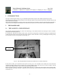
It is mounted on Derotator A and thus rotates with it. The NIA is composed of 4 main pieces (ranging in weight between
roughly 200 and 950 kg each) and several other minor elements. When mounted it is like a parallelepiped measuring nearly
0.5×2×4 meters. You can see a picture of NIA in Fig. 2-1.
Rotation axe
of NIA
Fig. 2-1: The Nasmyth Interface mounted on The Derotator A without instruments.
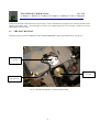
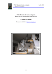
In the centre of NIA you can find the OIG cryostat (see Fig. 2-2). It is mounted on the rotation axe of the NIA also
containing the filter wheel system (see Section 2.3) and the sliding-carriage with the mirrors to direct the light to the IR
camera, to the AdOpt module, or just to allow it passing through for the OIG.
Between the NIA and the cryostat there is the OIG shutter (Section 2.4). Electronics racks with the OIG controller, filterwheel controller and shutter controller are placed on the external side of NIA and well accessible for technical operations
(see Section 2.5).
-2-
TNG: THE OIG USER MANUAL
June 2000
S. Benetti, C. Bonoli, R. Cosentino, D. Fantinel, A. Ghedina, E. Giro, A. Magazzù
All the instrumentation and NIA itself are powered by a remote controlled line starting from the telescope-derotator main
cabinet (power-plant floor). All instruments have their own multiple plug and can be remotely switched on and off
independently from the others.
2.2
THE OIG CRYOSTAT
The OIG cryostat is a custom modification of the standard INFRARED-LAB cryostat model ND-25. See Fig. 2-3.
The OIG
cryostat
The ARNICA
cryostat
The OIG CCD
controller rack
Fig. 2-2 The OIG and ARNICA cryostats mounted on NIA.
-3-
TNG: THE OIG USER MANUAL
June 2000
S. Benetti, C. Bonoli, R. Cosentino, D. Fantinel, A. Ghedina, E. Giro, A. Magazzù
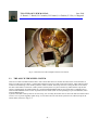
Fig. 2-3: Internal view of the cold plate with the CCD mosaic.
2.3
THE OIG FILTER WHEEL SYSTEM
There are 2 wheels mounted inside the NIA to select which filter has to be used for the OIG camera. Each wheel has 10
holes to provide space for 8 filters, 1 Atmospheric Dispersion Corrector (ADC) and a clear position. ADCs will be treated
as filters in the following so that 18 filter positions will be available. Obviously when one is using the filter of one wheel,
the other wheel will be on the clear or ADC position (actually there is no plan to mount any ADC and thus only the first
option is implemented). Each filter holder has a writable/readable EPROM and for each wheel there is a Baluff sensor to
write/read the EPROMs: there are then 18 positions for the wheels (each one corresponding to a pre-mounted filter) when
using the Baluff sensor.
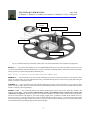
A picture of the filter wheel system can be seen in Fig. 2-4: obviously the shutter can't be seen when OIG is mounted. There
is also a cover to protect the filters which in Fig. 2-4 has been removed. The whole system for one wheel (except for the
wheel's brake) is drawn in Fig. 2-5.
-4-
TNG: THE OIG USER MANUAL
June 2000
S. Benetti, C. Bonoli, R. Cosentino, D. Fantinel, A. Ghedina, E. Giro, A. Magazzù
Baluff
Wheel
sensor
Brake
Limit switches
OIG shutter
Filter Wheel
Motor and encoder
Counter-torque motor
Fig. 2-4: The filter wheel system as seen from the outside of the NIA.
The program which allows operating the filter wheels is written in C and works under the PDOS operating system. The
executable program, TASK19.c, is physically on the hard disk partition number 12 of VMEOIG. All VME systems can
work in user or super mode; if in super mode (test and debugging phase) proceed as follows:
to get there one has to connect a terminal (or sort of) to the VMEOIG, then to go to the hard disk partition 12 (if not already
there) with the command:
>cd 12
and from there to start the GATE environment with:
>gate super.
All necessary tasks are spawned and a GATE prompt appears. From now on it is possible to send the commands, listed in
Tab. 2.1, to the filter wheels.
The command to exit from GATE is exit.
CONNST
INITFILT
CLEAR
FILTER
BALUFF
ROTABS
ROTREL
ENBRAKE
DISBRAKE
n
n
w val
w val
w
w
To check the connection status
To initialise the filters wheels
To select no filters
To select filter number n
To move filter number n under the Baluff sensor
To move the wheel w to the absolute position val
To move the wheel w of val counts
To close brakes on wheel w
To open brakes on wheel w
Tab. 2.1: List of commands to TASK19.
-5-
TNG: THE OIG USER MANUAL
June 2000
S. Benetti, C. Bonoli, R. Cosentino, D. Fantinel, A. Ghedina, E. Giro, A. Magazzù
CONNST - It is necessary to check the status of the connection between the VMEOIG and the NIA filter wheel before
sending any command. This check is performed by the command CONNST.
If there is exchange of information between the two systems a message appears:
"The OIG Filter Controller is connected"
If on the other hand the connection is not present one sees:
"ATTENTION: The OIG Filter Controller is NOT connected"
This is probably due to the fact that the power of the rack is switched off or the serial cable is not connected. Check these
two possibilities before proceeding.
INITFILT - This is a fundamental command if someone wants to drive the filter wheels in fixed positions, such as the
clear position and a filter or an EPROM specified by their number. It is anyway safer to use it always, soon after the
CONNST command.
If the connection is up, the filter wheels start to rotate and search fort their respective edges, then set to zero their encoder's
counts and move away from this position (they rotate roughly to the clear position). The whole procedure can take a few
minutes and in the meanwhile messages appear to inform the user about the correct (or wrong) proceeding of the
initialisation. Then the system is ready to receive safely any of the following commands.
It can often happen that, when the filter wheel is initialised being far from the edges' position, the system goes in Time Out.
For safety reasons, Time Out happens roughly 20 seconds after the beginning of the initialisation while it takes much more
time to the filter wheels to complete one whole turn during this phase. Anyway after 2 or 3 INITFILT commands the
procedure should be completed.
CLEAR - This is the command to let the light go directly to the OIG, with no filter absorption. After the initialisation the
filter wheels move next to this position but the command CLEAR should be sent anyway to be sure that the position is
reached.
FILTER n - Actually there are only 8 filters mounted on the #1 filter wheel. It is then logical to give to n only values
between 1 and 8. Greater values correspond to a CLEAR position, but with the inside of the filter holders not black
anodised. When the filter is in its position you can see a message like:
+++++ Filter 3 is There. Brakes On. +++++
-6-
TNG: THE OIG USER MANUAL
June 2000
S. Benetti, C. Bonoli, R. Cosentino, D. Fantinel, A. Ghedina, E. Giro, A. Magazzù
Filter holder
with filter
EPROM
Counter-torque motor
Main motor with encoder
Baluff sensor
Proximity sensors
Fig. 2-5: Schematic drawing of the filter wheel system. The other wheel has the same component arrangement.
BALUFF n - Each of the filter holders has its own Baluff EPROM When you give this command you choose to move
one of the filter EPROM under the Baluff sensor in order to read what is memorised there. After the movement of the filter
wheel you receive a printed message like the following one:
This filter is Johnson U:peak=368nm,pkTR=84%,FWHM= 93nm
ENBRAKE w - This command can be sent without initialising the system. It activates the brakes on one of the two filter
wheels. You don't need to give this command when using commands like the previous ones because opening and closing the
brakes is automatic in those procedures.
DISBRAKE w - This command can be sent without initialising the system. It opens the brakes on one of the two filter
wheels. You don't need to give this command when using commands like the previous ones because opening and closing the
brakes is automatic in those procedures.
ROTABS w val - This command could be sent without initialising the system. It moves one of the filter wheels to the
absolute position val. Never use this command if the system is not initialised OR if you don't know exactly what
could be the consequences. When the system is not initialised usually the encoder's counts start from the actual position
and can be both positives and negatives, with values ranging roughly from -1670000 to 1670000. If the wheels move very
fast, and is sent to an encoder value position which is further than the proximity sensors, it is possible that the proximity
sensors don't recognise the edge and thus are not able to stop the rotation in time. If this happens one can get the filter wheel
to be locked between the proximity edge and the mechanical edge.
-7-
TNG: THE OIG USER MANUAL
June 2000
S. Benetti, C. Bonoli, R. Cosentino, D. Fantinel, A. Ghedina, E. Giro, A. Magazzù
ROTREL w val - This command could be sent without initialising the system. It moves one of the filter wheels to the
relative position val. What is written for the previous command is still true here. Never use this command if the system
is not initialised OR if you don't know exactly what could be the consequences.
When working under VME it may be necessary to read the values of the global variables that are used by this task.
Should this occur one has to write from the GATE prompt:
>glob 400
The list of Tab. 2.2 appears, only with the number and value of the global variables, and the time of last modification. To
exit from the list the command is:
>Q (uppercase).
Name
#
INIT
BIUZ
BIUU
BIUD
BIUS
BIDZ
BIDU
BIDD
BIDS
FILT
BRA1
BRA2
POSU
POSD
ERP1
ERP2
CONX
BALU
400
401
402
403
404
405
406
407
408
409
410
411
412
413
414
415
416
417
Description
Initialisation status
Bit 0 status wheel 1
Bit 1 status wheel 1
Bit 2 status wheel 1
Bit 7 status wheel 1
Bit 0 status wheel 2
Bit 1 status wheel 2
Bit 2 status wheel 2
Bit 7 status wheel 2
Filter number
Brakes status of wheel 1
Brakes status of wheel 2
Position of wheel 1
Position of wheel 2
Error position of wheel 1
Error position of wheel 2
Connection status
Baluff EPROM number
Before
Init.
0
0
0
0
0
0
0
0
0
0
0
0
0
0
0
0
1
0
After Init.
Range values
1
0
1
0
0
0
1
0
0
0
1
1
25000
-33000
<5
<5
1
0
0,1
0,1
0,1
0,1
0,1
0,1
0,1
0,1
0,1
0,18
0,1
0,1
0,1670000
0,-1670000
± 1670000
± 1670000
0,1
0,18
Tab. 2.2: List of global variables used in TASK19.
Moving the filter wheel when working under the user interface environment is much easier.
There is only one button to press in order to check both the connection status and to initialise the filter wheel.
From a pop-down menu it is then possible to choose which filter to set for the observation. The same commands given
under VME can be sent from the command line in the user interface.
Solving Problems
If after 2 or 3 initialisations the filter wheel seems to be not responding correctly it is possible that it got stuck between the
mechanical edge and the proximity sensor. It is necessary to set it free with GATE commands, from the VME or from the
user interface (depending on which one you are using). It is a very simple procedure and it consists only in giving relative
movements to the wheel that got stuck with the command ROTREL w val (see above).
Just remember to give always positive values for wheel #1 and negative for wheel #2.
-8-
TNG: THE OIG USER MANUAL
June 2000
S. Benetti, C. Bonoli, R. Cosentino, D. Fantinel, A. Ghedina, E. Giro, A. Magazzù
2.4
THE OIG DOUBLE-BLADE SHUTTER
The OIG double-blade shutter is designed to cover the whole field of the optical imager. The working area is 80 X 80 mm
and the dimension is 220 X 150 X 35 mm. Thanks to a peculiar double blade mechanics and a two step motor driving
system, the shutter assures a uniformity of exposure time of ± 0.8 ms over the whole field when exposed for 1 sec, while
minimum exposure time is 10 ms.
The present OIG user -interface allows the operator to insert a minimum exposure time of 0.1 Sec, we found this minimum
exposure time doesn’t introduce any appreciable error on the taken frames.
The control electronics is located in the filter control rack and provides a simple interface to the CCD controller.
Fig. 2-6 shows the shutter block diagram and Fig. 2-7 shows the operating modes of the shut ter. A schematic drawing of
the curtains inside the shutter is shown in Fig. 2-5.
Fig. 2-6: Shutter block diagram.
-9-
TNG: THE OIG USER MANUAL
June 2000
S. Benetti, C. Bonoli, R. Cosentino, D. Fantinel, A. Ghedina, E. Giro, A. Magazzù
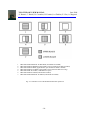
1.
2.
3.
4.
5.
6.
7.
THE SHUTTER IS READY TO BE OPEN (both blades are loaded)
THE SHUTTER IS OPENING (upper blade is moving while lower blade is loaded)
THE SHUTTER IS OPEN (upper blade is open while lower blade is loaded)
THE SHUTTER IS CLOSING (upper blade is open and lower blade is moving)
THE SHUTTER IS CLOSE ( both blades are open)
THE SHUTTER IS CLOSE (both blade are loaded)
THE SHUTTER IS READY TO OPEN (both blades are loaded)
Fig. 2-7: Schematic view of the double-blade shutter operations.
- 10 -
TNG: THE OIG USER MANUAL
June 2000
S. Benetti, C. Bonoli, R. Cosentino, D. Fantinel, A. Ghedina, E. Giro, A. Magazzù
Fig. 2-8: Schematic drawing of the curtains inside the shutter.
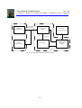
2.5
THE OIG CCD-CONTROLLER (CCDC)
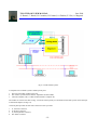
The architecture of the CCD’s readout system in shown in Fig. 2-9. The first block is the CCD controller, which is located
close to the cryostat. Into the CCD controller there is a bus (called “CCD controller bus”), in which are plugged-in a
sequencer board and at least one analog board.
The sequencer board generates the clock sequences. Each analog board produces 8 programmable “bias voltages”, 16 clock
drivers with independently programmable up and low levels. Each board is able to read and process four channels
independently.
This controller allows different readout modes:
- Full frame
- Frame transfer
- Binning on chip
- Windows
The controller is connected by optical fibers to a VME crate. This one contains:
• a shared memory for image storing;
• a transputer for commands dispatching to the controller;
• an Ethernet connection to the TNG workstation system.
- 11 -
TNG: THE OIG USER MANUAL
June 2000
S. Benetti, C. Bonoli, R. Cosentino, D. Fantinel, A. Ghedina, E. Giro, A. Magazzù
Fig. 2-9: CCDs readout system.
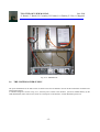
A complete CCD controller system is made by three parts:
1. The CCD Controller (CCDC) main rack;
2. The camera cryostat with the detector, amplifiers and bias buffers;
3. The host-computer (a PC, a VME connected inside a computer net).
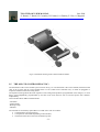
The CCDC 19″ main rack is shown in Fig. 2-10 (front and rear panel); it is mounted near the OIG cryostat on the NasmythA instrument adapter (see Fig. 2-2).
The front panel provides the four main connectors to the cryo-head:
1.
2.
3.
4.
J1, the clock connector;
J2, the bias connector;
J3, the temperature connector;
The shutter connector
- 12 -
TNG: THE OIG USER MANUAL
June 2000
S. Benetti, C. Bonoli, R. Cosentino, D. Fantinel, A. Ghedina, E. Giro, A. Magazzù
The rear panel shows the following parts:
1.
2.
3.
4.
5.
The ON/OFF power switch;
The main plugs;
The 4 plugs for the fiber-link;
The DSP and the TRANSPUTER control LEDS (Green and Red respectively);
The switch for the LED inhibition.
J1-connector
CCD-clocks
J3-connector
Temperature controller
J2-connector
CCD bias
Shutter
connector
Thermoelectric
head temperature
setting
DSP&Tputer
LEDs
Mains input &
power switch
Fibre optic- link
connectors
Fig. 2-10: CCDCTRL front and rear sides of the main box.
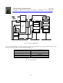
In Fig. 2-11 one can see a block diagram of the main parts of the CCD controller system and in Fig. 2-12 the VMEOIG rack
is shown.
- 13 -
TNG: THE OIG USER MANUAL
June 2000
S. Benetti, C. Bonoli, R. Cosentino, D. Fantinel, A. Ghedina, E. Giro, A. Magazzù
fibre-optic DS link
1Km max distance
VME/VSB
transputer adapter
sequencer board
CCDSEQ
CCD cryostat
pre-amplifier with clamp
internal bus
PCI BUS
transputer adapter
correlated double
sampler board
CCDCDS
power supply
host dapter interface
system
CCDCTRL box
Fig. 2-11: Main parts of the CCD controller system.
- 14 -
TNG: THE OIG USER MANUAL
June 2000
S. Benetti, C. Bonoli, R. Cosentino, D. Fantinel, A. Ghedina, E. Giro, A. Magazzù
Fig. 2-12: VMEOIG rack.
2.6
THE SYSTEM POWER SUPPLY
The power distribution for the OIG camera is based on the same architecture used for all the instruments mounted at the
Nasmyth A interface.
A schematic diagram is shown in Fig. 2-13; the main power switch to the derotator systems is handled directly by the
VME-SERVICES (TNG control room) witch can switch power to the derotator-A main distribution power-box.
- 15 -
TNG: THE OIG USER MANUAL
June 2000
S. Benetti, C. Bonoli, R. Cosentino, D. Fantinel, A. Ghedina, E. Giro, A. Magazzù
DIG-OUT channels/pins
16
c24
17
c23
+24Vcc 3
GND 5
16
220-AC NAS-B
OIG
POWER
SUPPLY
RACK Q1
Power Plant
NAS-A power ON/OFF
+24 Vcc
220-AC NAS-A
DIG-OUT
NAS-B power ON/OFF
RS232
PORT 1
DIG-IN
ATXdual port memory
CHA2
OIG-PW plug-1
VME-SERVICES
ATX-361
A
C
AC plugs
with ON-OFF
switch
NASMYTH-A
INSTRUMENT I/F
Power Distribution
Box
(PI C-808)
BAYTECH
RS232-MUX
VME-OIG
A
C
RS232
PORT 2
ELTEC
E-VII
+
GATE
A
C
ELTEC
E-VI
+
GATE
CCD
CONTROLLER
FILTER WHEEL
CONTROLLER
RS232
PORT 2
ETHERNET
Fig. 2-13: OIG power distribution.
Once the main distribution power-box is powered, again the VME-SERVICES, can, through a serial connection switch
power to the services in Tab. 2.3 via the control panel of Fig. 2-14:
220 Vacc plugs
1
2
3
4
5
6
service
OIG
ARNICA-NICS
ADOPT
SH-CAM
TRK-CAM
DEROTATOR
Tab. 2.3: Powered systems.
- 16 -
TNG: THE OIG USER MANUAL
June 2000
S. Benetti, C. Bonoli, R. Cosentino, D. Fantinel, A. Ghedina, E. Giro, A. Magazzù
Fig. 2-14: Control panel for Telescope services.
- 17 -
TNG: THE OIG USER MANUAL
June 2000
S. Benetti, C. Bonoli, R. Cosentino, D. Fantinel, A. Ghedina, E. Giro, A. Magazzù
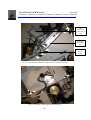
The
derotator-A
power switch
box
The OIG
filter-wheel
box
The OIG
power
socket
Fig. 2-15: The OIG filter-wheel box and the OIG power distribution socket.
Fig. 2-16: The OIG cryostat and the OIG controller box.
- 18 -
TNG: THE OIG USER MANUAL
June 2000
S. Benetti, C. Bonoli, R. Cosentino, D. Fantinel, A. Ghedina, E. Giro, A. Magazzù
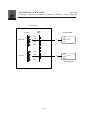
VMEOIG-LRS
64Mb
MEM
ATX-240
OIG-CCDCTRL
1-GR
M2M3AOPT
3-BR
fiber
1-GR
2-BL
3-BR
4-OR
OIG-CTRL
fiber
1-GR
2-BL
3-BR
4-OR
LRS-CTRL
4-OR
2-BL
1-GR
3-BR
M1AOPT
4-OR
2-BL
LRS-CCDCTRL
- 19 -
TNG: THE OIG USER MANUAL
June 2000
S. Benetti, C. Bonoli, R. Cosentino, D. Fantinel, A. Ghedina, E. Giro, A. Magazzù
3
THE SOFTWARE
3.1
THE CCD SOFTWARE
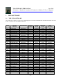
The CCD control software is written in OCCAM language; see the CCD CONTROLLER SYSTEM manual for more info.
In Tab. 3.1 there is a list of available commands.
INDEX
0
1
2
3
4
5
6
7
8
9
10
11
12
13
14
15
16
17
18
19
20
21
22
23
24
25
26
27
28
29
30
31
32
33
34
35
36
37
38
39
OCCAM
OPCODE
OPCD.SETSA
OPCD.SETSB
OPCD.SETLC
OPCD.XMDUMP
OPCD.YMDUMP
OPCD.GETID
OPCD.SETLED
OPCD.SETGLED1
OPCD.LOADTAB
OPCD.DOSCAN
OPCD.WIPE
OPCD.TONOFF
OPCD.BSHUTCR
OPCD.RDBSTIME
OPCD.CLCOUNT
OPCD.ISHUT
OPCD.SCCDTEMP
OPCD.RDTEMP
OPCD.SETSTS1
OPCD.SETAREA
OPCD.SETBOX
OPCD.SETRMODE
OPCD.BINNING
OPCD.NCCD
OPCD.SETRLED1
OPCD.CKHIGH1
OPCD.CKLOW1
OPCD.VOFS1
OPCD.WLESREG1
OPCD.SETBIAS
OPCD.TLMSTART
OPCD.TLMSTOP
OPCD.EXPOSE
OPCD.STOP
OPCD.ABORT
OPCD.PAUSE
OPCD.RESUME
OPCD.EXTEND
OPCD.BOOTDSP
OPCD.TNODE
DESTINATION OPERAND
NUMBER
DSP560.PE
1
DSP560.PE
1
DSP560.PE
2
DSP560.PE
1
DSP560.PE
1
DSP560.PE
0
DSP560.PE
1
DSP560.PE
1
DSP560.PE
1
DSP560.PE
2
BROAD
1
DSP560.PE
1
DSP560.PE
1
DSP560.PE
0
DSP560.PE
0
DSP560.PE
1
DSP560.PE
1
DSP560.PE
1
DSP560.PE
1
BROAD
2
BROAD
4
BROAD
1
BROAD
2
BROAD
1
LES1.PE
1
LES1.PE
2
LES1.PE
2
LES1.PE
2
LES1.PE
2
LES1.PE
2
ATX260.PE
1
ATX260.PE
0
ATX260.PE
3
ATX260.PE
0
ATX260.PE
0
ATX260.PE
0
ATX260.PE
0
ATX260.PE
1
ATX260.PE
0
NODE.PE
1
- 20 -
ACTION
MODE
NOWAIT
NOWAIT
NOWAIT
WAIT
WAIT
WAIT
NOWAIT
NOWAIT
NOWAIT
NOWAIT
WAIT
NOWAIT
NOWAIT
WAIT
NOWAIT
NOWAIT
NOWAIT
WAIT
NOWAIT
WAIT
WAIT
WAIT
WAIT
WAIT
NOWAIT
NOWAIT
NOWAIT
NOWAIT
NOWAIT
NOWAIT
NOWAIT
NOWAIT
NOWAIT
NOWAIT
NOWAIT
NOWAIT
NOWAIT
NOWAIT
NOWAIT
WAIT
OPERAND
CLASS
NUM
NUM
NUM
NUM
NUM
NUM
NUM
NUM
STRING
NUM
NUM
NUM
NUM
NUM
NUM
NUM
NUM
NUM
NUM
NUM
NUM
NUM
NUM
NUM
NUM
NUM
NUM
NUM
NUM
NUM
NUM
NUM
NUM
NUM
NUM
NUM
NUM
NUM
NUM
NUM
GATE
ACRONYM
setsa
setsb
setlc
xmdump
ymdump
getid
setled
setgled1
loadtab
doscan
wipe
tonoff
bhutcr
rdbstime
clcount
ishut
sccdtemp
rdtemp
setsts1
setarea
setbox
setrmode
binning
nccd
setrled1
ckhigh1
cklow1
vofs1
wlesreg1
setbias
tlmstart
tlmstop
expose
stop
abort
pause
resume
extend
bootdsp
tnode
TNG: THE OIG USER MANUAL
June 2000
S. Benetti, C. Bonoli, R. Cosentino, D. Fantinel, A. Ghedina, E. Giro, A. Magazzù
40
41
OPCD.FSHOT
OPCD.SETVDD
DSP560.PE
ATX260.PE
1
2
NOWAIT
NOWAIT
NUM
NUM
fshot
setvdd
Tab. 3.1: List of CCD commands.
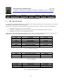
3.2
THE VME SOFTWARE
The OCCAM code handling CCD cameras is the same for ALL cameras mounted at the TNG telescope; that is commands
and telemetry responses are the same for all systems.
Each camera is controlled by a dedicated VME crate mounting GATE software. VMEs involved in camera handling are:
•
•
•
VMEOIG (vmeoig.tng.iac.es) for OIG instrument;
VMEAOPT (vmeaopt.tng.iac.es) for Active Optic system and Tracking and Shack-Hartmann cameras;
VMELRS (vmelrs.tng.iac.es) for DOLORES instrument.
VME software (GATE) has some tasks to manage the system that are common to all VME crates; they are listed in Tab. 3.2.
Applicative tasks are system-dependent and are listed in Tab. 3.3, in Tab. 3.4 and in Tab. 3.5.
TASK-ID
GATE
TASK1
TASK2
TASK3
TASK4
TASK5
TASK6
TASK10
FUNCTION
Task Handler
Micro-commands from WS
Micro-commands dispatching
Alarms Handling
Telemetry to WS
Images to WS or to disk
Global access Handling
Heart beat
RUN-TIME MODE
user/super
User
User
user/super
User
user/super
user/super
User
Tab. 3.2: GATE common tasks.
TASK12
TASK13
TASK15
TASK19
OIG telemetry
OIG controller commands
OIG boot command
OIG filter wheel Handling
user/super
user/super
user/super
user/super
Tab. 3.3: OIG tasks.
TASK11
TASK12
TASK13
TASK15
AOPT commands
AOPT telemetry
Tracking and SH cameras
Miscellaneous commands
Tab. 3.4: AOPT and Tracking tasks.
- 21 -
user/super
user/super
user/super
user/super
TNG: THE OIG USER MANUAL
June 2000
S. Benetti, C. Bonoli, R. Cosentino, D. Fantinel, A. Ghedina, E. Giro, A. Magazzù
TASK12
TASK13
TASK15
LRS telemetry
LRS controller commands
LRS boot command
user/super
user/super
user/super
Tab. 3.5: DOLORES tasks.
Each task is stored inside a subdirectory of the working disc partition (/taskxx) holding the source code (TASKxx.c) and
the compilation script (DOTASKxx), while the executable code (taskxx) is stored in the /bin directory. Working partitions
for all systems are summarized in Tab. 3.6.
SYSTEM
OIG
Tracking, Shack-Hartmann
DOLORES
DISK LU
12:/
13:/
12:/
Tab. 3.6: Camera software working directories.
The camera software foresees the subdirectories:
•
/ccdtables to hold the boot table directories for CCDs; they are:
/eev1
/eev2 /eev3 /loral1 /loral2 /loral3
according to the chip mounted on the system; the table to load is selected by the first parameter (OIG and DOLORES)
or second parameter (Tracking and Shack-Hartmann) of the loadboot command according to the following scheme:
1
2
3
4
5
6
eev1
eev2
eev3
loral1
loral2
loral3
it also stores the CCD controller compatibility file to check the correspondence between the selected code (controller)
and the allowed range for the chip. For more detailed information see the TNG CONTROLLER SYSTEM manual.
•
/boot to hold the OCCAM executable code for the CCD controllers; they are:
oig.btl
sha.btl shb.btl tra.btl trb.btl lrs.btl
according to destination system; for technical cameras the bootable file to load is selected by the first parameter of the
loadboot command according to the following scheme:
2
3
4
5
tra.btl
sha.btl
trb.btl
shb.btl
board1
board2
board1
board2
2000
3000
2000
3000
- 22 -
TNG: THE OIG USER MANUAL
June 2000
S. Benetti, C. Bonoli, R. Cosentino, D. Fantinel, A. Ghedina, E. Giro, A. Magazzù
3.3
THE WORKSTATION SOFTWARE
Communications between VME software and OIG user interface are permitted by WSS. Its main duty consists in updating
commands and telemetry queues between OIG Workstation (WSOIG) and OIG VME (VOIG). From WSS it is possible to
start OIG User Interface simply clicking the relative button on the Nasmyth A panel.
3.4
THE MAIN USER INTERFACE SOFTWARE
When user interface is started the panel of Fig. 3-1will appear to the user. This panel is divided into two main parts. On the
left a quick look is present, while the right part permits the user to control the instrument. At least on the top of the window
the user can access to a pull down menu for other functionalities (see below). Referring to Fig. 3-1 the typical user
operations will be described.
Quick look facility appears divided into five parts. On the left a main window displays full resolution image. Under this
window there are two slides to manually set cuts and two buttons devoted to set automatic cuts and to perform a simple TV
scaling of the image. The graphic window is active, in the sense that the user can use it interactively with the mouse
buttons:
• Right button: a square cursor will appear to the user to select a sample. The central part of the sample (the inner
square) will be considered the star signal, while the outer area will be considered sky. To change sample dimensions
click on one corner of the box with central button and drag it. A maximum of 400x400 pixels area is permitted. To
change box position draw it with the left button. At this point there are two possibilities to confirm the choice.
• right button. At this point a Statistics window (see fig.*** ) will appear. In the top of this window a tabular
representation of the most important statistical quantities is reported:
1. FWHM x: the FWHM (“) along rows if gaussfit converges;
2. FWHM y: the FWHM (“) along columns if gaussfit converges;
3. X position in pixels;
4. Y position in pixels;
5. Minimum value in the box;
6. Maximum value in the box;
7. Mean value in the box;
8. Sky level;
9. RMS (adu) in the box;
10. Total signal in the box;
11. Offset in R.A. (arcsec) to put the selected object the in position of the desired marker;
12. Offset in DEC (arcsec) to put the selected object the in position of the desired marker;
13. Angle of major axis of the elliptical gaussfit
14. Selection of the desired marker on which to calculate the offset;
15. Button to calculate the telescope offset.
•
In the bottom of the window is present a 3-D representation of the sampled box. Using the controls under this plot
it is possible to change the point of view of the representation. It is possible to switch to a 2-D representation cut
along rows.
Double click right button: Now the same cursor enables the user to choose the coordinates of a box on the two chips.
These coordinates are reported in the sequencer table in the box fields (see later).
- 23 -
TNG: THE OIG USER MANUAL
June 2000
S. Benetti, C. Bonoli, R. Cosentino, D. Fantinel, A. Ghedina, E. Giro, A. Magazzù
Fig. 3-1: The OIG main user interface.
The other windows in the left part show:
• a zoomed part of the image, moving mouse on the main display window the centre of zoomed region consequently
changes, zooming factor is set using the slider under this window.
• A full frame image to show the selected positions of the markers. Clicking on elsewhere position puts this position in
the centre of the main display window.
The right part of the main interface is dedicate d to display actual camera settings and statistics. In particular there are:
• A log box for the messages between interface and low level CCD software;
• A box of quick access statistic (x y and pixel value at the position of cursor);
• A facility to set the positions of the markers;
• The order number of exposition (see sequencer interface section);
• Object’s name;
• Archive flag;
- 24 -
TNG: THE OIG USER MANUAL
June 2000
S. Benetti, C. Bonoli, R. Cosentino, D. Fantinel, A. Ghedina, E. Giro, A. Magazzù
•
•
•
•
•
Eventual comment;
CCD box;
exposure’s type;
button to activate sequencer;
button to control CCD (stop, abort, transmit, pause, resume, extend commands). To extend exposition put the number
of seconds with sign to add in the left field ext t .
During an exposition a timer slider appears at the bottom of the window.
In the bottom part of the window two plots are displayed:
• profiles in row and column activated with left click of mouse;
• statistic of counts over a box of 40x40 pixels.
At the end other four controls are present:
• a command input to send single commands to the low level;
• an option between row and column for profiles plot;
• a button to activate automatic focus procedure;
• a status bar.
In the right bottom part a button permits to open boot interface.
3.4.1 The Boot Interface
The boot interface permits to boot the transputer network with different boot tables. The window on the left shows a
schematic view of the transputer net. In the left five buttons permit to perform several action:
• Boot: boot the net with selectable tables (it is a pull down menu);
• Test net: test the functionality of the transputer network. When boot is loaded the system waits until VME sends
acknowledgement to the interface. In the bottom part the commands sent to CCD are displayed.
• View: (?)
• Ispy: load ispy;
• Done: quit from boot interface.
- 25 -
TNG: THE OIG USER MANUAL
June 2000
S. Benetti, C. Bonoli, R. Cosentino, D. Fantinel, A. Ghedina, E. Giro, A. Magazzù
Fig. 3-2: The Statistics window.
Fig. 3-3: The boot interface
- 26 -
TNG: THE OIG USER MANUAL
June 2000
S. Benetti, C. Bonoli, R. Cosentino, D. Fantinel, A. Ghedina, E. Giro, A. Magazzù
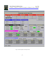
3.4.2 The Sequencer Interface
Fig. 3-4: The sequencer interface
This window permits to activate a sequence of exposures. It is activated using the sequencer button in the main window
interface. Its layout is shown in Fig. 3-4: it is a table of 10 exposure definitions in which the user can choose different set up. Typically each line is composed by 11 fields:
• An activation button. If the button is activated the line is posed in the sequence.
• An exposure type list. The user can choose between [Flat, Dark, Bias, Object, Wipe].
• A repeat field. The selected exposure can be repeated until 9 times;
• An identifier field. This string will be put on the IDENTIFIER filed of fits header;
• An exposure field. The exposure time;
• A filter list. The user can choose between 18 positions on the two filter wheels;
• 4 fields for the CCD boxing: left and right columns, down and up rows. The default is the full frame CCD area;
• A save button. If set the image will be archived.
On the bottom of the window 5 buttons and a text field are present. Their functionalities are the following:
- 27 -
TNG: THE OIG USER MANUAL
June 2000
S. Benetti, C. Bonoli, R. Cosentino, D. Fantinel, A. Ghedina, E. Giro, A. Magazzù
•
•
•
•
•
•
Serrourier Temperature: this field permits the user to define, using serrourier temperature, the starting point of M2
position for automatic focus sequence;
START: start exposure sequence;
LOAD: load a predefined exposure sequence on the window table;
SAVE: save a defined exposure sequence;
RESET: rewrite the default values of sequence;
QUIT: exit and destroy sequencer window.
3.4.3 Menu Functionality
Here is briefly described the top menu with its hierarchy.
•
•
•
•
•
•
•
File
• Load: Load a binary image from disk;
• Save: Save an image in binary format;
• Print: Print an hardcopy of the image;
• Exit: Exit from user interface.
Edit
• Open: Open an image in FITS format;
• Save: Save an image in FITS format;
Telemetry
• One Shot: Instantaneous telemetry from CCD;
• Start Telemetry: Start a loop of telemetry (the refresh time is set by the user);
• Stop Telemetry: Stop a telemetry loop;
• Image Telemetry: Display telemetry from image binary header.
CCD Status: Some important CCD settings. Among them CCD area ( x pixels, y pixels), Box dimension and position (x
pixels, y pixels), binning, and number of chip.
Palette: a color editor utility to better display the image;
Help:
• Commands: A simple command help;
Read Mode: This command MUST BE USED VERY CAREFULLY
• 2 output left: CCD is read form two left outputs;
• 2 output right: CCD is read form two right outputs;
• 4 output: CCD is read from four outputs. In this setting CCD boxing is not allowed.
- 28 -
TNG: THE OIG USER MANUAL
June 2000
S. Benetti, C. Bonoli, R. Cosentino, D. Fantinel, A. Ghedina, E. Giro, A. Magazzù
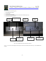
3.4.4 The Telemetry Interface
Fig. 3-5: The telemetry interface
From the top menu it is possible to open the window shown in Fig. 3-5. The quantities reported in this window are the same
written in the binary header of each image. The window is divided into four parts:
• Clocks: there are 16 fields corresponding to the 16 levels of clocks;
• Bias: 8 fields for the 8 bias levels;
• Temperatures: the 5 temperature (°K) sensors placed on CCD, vessel, shield, cryostat wall and electronic control. A
sixth sensor is not connected (NC)
• General Status: in this part all the other telemetry values are placed. In particular about CCD setting we have: chip area
dimensions (in x and y pixel), box dimensions (in x and y pixel), position of the left down corner of the box in the chip,
read-out mode, exposure time of the last exposure, system identifier (ID), binning and the four ground levels.
- 29 -
TNG: THE OIG USER MANUAL
June 2000
S. Benetti, C. Bonoli, R. Cosentino, D. Fantinel, A. Ghedina, E. Giro, A. Magazzù
Telemetry window can be activated with various settings, to display instantaneous telemetry, looped or image telemetry.
These possibilities are choose from the top menu.
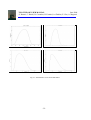
3.4.5 Auto Focus
In the OIG user interface it is also implemented an auto focus procedure. It consists essentially in a sequence of images
with different M2 positions. The different FWHM are calculated and a 2nd order polynomial fit is obtained. The parabola
minimum is the best focus position.
To use this facility perform the following instructions:
• Take a full frame image;
• Open the sequencer and load the file focus.exp;
• Select a box with one star in the left chip;
• Edit the repeat field in the sequencer. You can choose between 3 and 9 exposure. A good choice may be 6;
• Fill the temperature field in the bottom left;
• Start exposures;
• At the and of the sequence click focus button on the bottom of the main window;
• A window like Fig. 3-6: will be displayed;
• Eventually deselect some wrong measurements;
• Press calculate. Two parabolas, x and y fit, and the calculated focus positions will be displayed.
Fig. 3-6: The focus window
- 30 -
TNG: THE OIG USER MANUAL
June 2000
S. Benetti, C. Bonoli, R. Cosentino, D. Fantinel, A. Ghedina, E. Giro, A. Magazzù
4
4.1
ASTRONOMY
THE FILTER SYSTEM
The presently available filters and their main characteristics are listed in Tab. 4.1::
Filter
U
B
V
R
g
r
i
z
Peak
WL.
nm
367
445
523
592
493
638
828
870
Centr.
WL.
nm
361
436
533
625
518
659
825
~900
Peak Tr. FWHM
%
nm
67
67
84
82
82
86
85
90
60
103
93
128
103
81
192
~140
Tab. 4.1: Filters characteristics
They are identified on the CCD user interface directly with the corresponding name. The 10 filter positions still free
(basically all in the wheel #2) can be filled with user-provided filters.
In this case the filters should have a diameter of 106.0 +/- 0.2 mm and a thickness of less than 10.0 mm.
In the following Fig. 4-1, you can find the transmittance curves for the OIG filters, as given by the manufacturer.
- 31 -
TNG: THE OIG USER MANUAL
June 2000
S. Benetti, C. Bonoli, R. Cosentino, D. Fantinel, A. Ghedina, E. Giro, A. Magazzù
Fig. 4-1: Transmittance curves for the OIG filters.
- 32 -
TNG: THE OIG USER MANUAL
June 2000
S. Benetti, C. Bonoli, R. Cosentino, D. Fantinel, A. Ghedina, E. Giro, A. Magazzù
Fig. 4-2: Gunn filters.
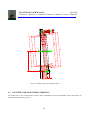
4.1.1 Filter Mechanics
The two OIG filter wheels can allocate 9 filters each (two holes are permanently empty) for a total of 18 filters continuously
available.
Custom filters can be inserted temporarily on the system provided they can fit with the dimensions of the filter cage shown
in Fig. 4-3.
- 33 -
TNG: THE OIG USER MANUAL
June 2000
S. Benetti, C. Bonoli, R. Cosentino, D. Fantinel, A. Ghedina, E. Giro, A. Magazzù
2
3
4
10
4
o0a2r3xi 5
1f2Mn
2
16
°106 °102 Luce
°1 2 4
°1 0 9
°1 1 6
5
sun
7
n °1 1 0
90
3
6.1
Fig. 4-3: The filter cage on the OIG filter wheel.
4.2
OIG DETECTOR MAIN CHARACTERISTICS
.
The CCDs used in TNG instrumentation are EEV 4280 (2048x4096) and Loral (2048x2048). Their characteristics are
summarized in the following Tab. 4.2.
5
- 34 -
TNG: THE OIG USER MANUAL
June 2000
S. Benetti, C. Bonoli, R. Cosentino, D. Fantinel, A. Ghedina, E. Giro, A. Magazzù
Manufacturer
Chip Type
Pixel size
Area
Readout noise
MPP
Working temp.
UV treatment
AR Coating
Grade
LORAL
Thinned Back illuminated
15 µm
2048 × 2048
12 e
Yes
-110 C
Chemiosorption (Cu layer)
Yes
2 (both)
EEV4280
Thinned Back illuminated
13.5 µm
2048 × 4096
10 e
No
-130 C
Ion implantation
Yes
2&3
Tab. 4.2: CCD’s characteristics
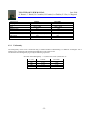
4.2.1 Uniformity
The homogeneity of the CCD is measured using a standard method of illuminating it at different wavelengths with a
uniform source of radi ation and calculating the RMS all over the sensitive area.
The deviation from homogeneity is given by the following expression:
Deviation form Homogeneity = σ (whole area) / mean (whole area) %
λ (nm)
400
550
700
900
LORAL
3.2 %
3.4 %
3.3 %
3.7 %
EEV4280
3.9 %
3.4 %
5.7 %
5.2 %
Tab. 4.3: Deviation from uniformity
- 35 -
TNG: THE OIG USER MANUAL
June 2000
S. Benetti, C. Bonoli, R. Cosentino, D. Fantinel, A. Ghedina, E. Giro, A. Magazzù
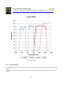
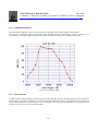
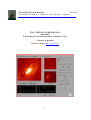
4.2.2 Quantum Efficiency
The CCD quantum efficiency (QE) was measured in the wavelength interval 2000 10500 Å in incremental
The CCD was illuminated using monochromatic light obtained through a Xenon lamp, a series of filters and a
monochromator. The signal integrated on the CCD is then compared to the response of a calibrated photodiode.
Fig. 4-4: QE of the EEV 4280
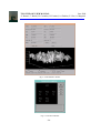
4.2.3 Dark Current
The dark current is measured taking a short dark exposure and a long dark exposure. The signal level in the two exposures is
then compared. The frame is divided in 10´10 pixel sub-frames and the dark current is computed for each of them. The
results of this procedure are shown in figure **** as a histogram in the case of the CCD EEV42-80. The average value of
the dark current turns out to be 6 electrons/pixel/hour.
- 36 -
TNG: THE OIG USER MANUAL
June 2000
S. Benetti, C. Bonoli, R. Cosentino, D. Fantinel, A. Ghedina, E. Giro, A. Magazzù
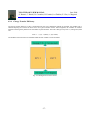
4.2.4 Charge Transfer Efficiency
The charge transfer efficiency (CTE) is measured using the X-ray stimulation method. In particular, the parallel CTE is
obtained exposing the CCD to the Fe55 source for a given amount of time. After integration, the columns are stacked
together and the signal is plotted versus the number of pixel transfers. The CTE is then given by CTE=1- (Charge loss)/1620
e/N
CTE = 1 – ( s(0) – s(4095) ) / ( s(0) * 4096)
The LORAL CTE turned out to be 0.999982 while the EEV exhibits a CTE of 0.99999.
Fig. 4-5: Misalignment of OIG’s mosaic
- 37 -
TNG: THE OIG USER MANUAL
June 2000
S. Benetti, C. Bonoli, R. Cosentino, D. Fantinel, A. Ghedina, E. Giro, A. Magazzù
Manufacturer
Linearity
Uniformity
CTE
Quantum Efficiency at:
400 nm
600 nm
900 nm
LORAL-OIG
<0.15%
3.4
0.99998
EEV4280
<0.5
4.8
0.99999
92%
80%
30%
82%
94%
41%
12e
4e
Read-out Noise
Conversion factor chip SX
Conversion factor chip DX
1 e/ADU
1 e/ADU
Readout time:
Binning X 1
Binning X 2
Binning X 3
Tab. 4.4: ****
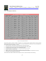
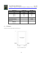
4.3
CCD IMAGE
The structure of the CCD EEV4280 is showed in Fig. 4-6.
Fig. 4-6: EEV4280 structure.
- 38 -
TNG: THE OIG USER MANUAL
June 2000
S. Benetti, C. Bonoli, R. Cosentino, D. Fantinel, A. Ghedina, E. Giro, A. Magazzù
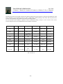
The image area of the CCD is 2048 X 4100 pixel, while the length of the output register is 2148 pixel. The dimension of the
image produced by the acquisition system is 2148 X 4200 pixels (without binning). This means that the prescan and
overscan zones depends by the readout mode and by the binning utilised.
The User Interface allows different acquisition modes and different binning on chip. In Tab. 4.5 and in Tab. 4.6 the
overscan and prescan zones for the different kind of acquisition are showed.
Readout Mode
Binning
Image Size
X prescan
X image
X Overscan
Y overscan
Left
1X1
2148 X 4200
0 - 49
50-2097
2098 - 2147
4100-4199
Right
1X1
2148 X 4200
2098 - 2147
50-2097
0 - 49
4100-4199
Two outs
1X1
2148 X 4200
0 – 49
2098 - 2147
50-2097
NO
4100-4199
Left
2X2
1074 X 2100
0-24
25-1048
1049-1073
2050-2099
Right
2X2
1074 X 2100
1049-1073
25-1048
0-24
2050-2099
Two outs
2X2
1074 X 2100
0-24
1049-1073
25-1048
NO
2050-2099
Left
3X3
716 X 1400
0-15
16*- 698
699*- 715
1367-1399
Right
3X3
716 X 1400
699*- 715
16*- 698
0-15
1367-1399
Two outs
3X3
716 X 1400
0-15
699*- 715
16*- 698
NO
1367-1399
Tab. 4.5: EEV #1
- 39 -
TNG: THE OIG USER MANUAL
June 2000
S. Benetti, C. Bonoli, R. Cosentino, D. Fantinel, A. Ghedina, E. Giro, A. Magazzù
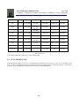
Readout Mode
Binning
Image Size
X prescan
X image
X Overscan
Y overscan
Left
1X1
2148 X 4200
2148-2197
2198-4245
4246-4295
4100-4199
Right
1X1
2148 X 4200
4246-4295
2198-4245
2148-2197
4100-4199
Two outs
1X1
2148 X 4200
2148-2197
4246-4295
2198-4245
NO
4100-4199
Left
2X2
1074 X 2100
1074-1098
1099-2122
2123-2147
2050-2099
Right
2 X2
1074 X 2100
2123-2147
1099-2122
1074-1098
2050-2099
Two outs
2X2
1074 X 2100
1074-1098
2123-2147
1099-2122
NO
2050-2099
Left
3X3
716 X 1400
716-731
732*- 1414
1415 * - 1431
1367-1399
Right
3X3
716 X 1400
1415 * - 1431
732*- 1414
716-731
1367-1399
Two outs
3X3
716 X 1400
716-731
1415 * - 1431
732*- 1414
NO
1367-1399
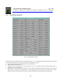
Tab. 4.6: EEV #2
*) The value of this pixel is a mean of overscan and image area.
4.4
FLAT-FIELDING OIG
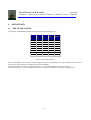
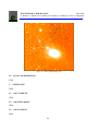
In the following examples of U, B, V, R, i normalised sky flat fields are given in Fig. 4-7 to Fig. 4-11. The images cut are
0.95, 1.05. The i flat field does not show any fringing because the twilight light has a continuum spectrum. An example of
scientific i image with the typical fringing pattern is given in the following figures.
- 40 -
TNG: THE OIG USER MANUAL
June 2000
S. Benetti, C. Bonoli, R. Cosentino, D. Fantinel, A. Ghedina, E. Giro, A. Magazzù
Fig. 4-7: U Bessel
- 41 -
TNG: THE OIG USER MANUAL
June 2000
S. Benetti, C. Bonoli, R. Cosentino, D. Fantinel, A. Ghedina, E. Giro, A. Magazzù
Fig. 4-8: B Bessel
- 42 -
TNG: THE OIG USER MANUAL
June 2000
S. Benetti, C. Bonoli, R. Cosentino, D. Fantinel, A. Ghedina, E. Giro, A. Magazzù
Fig. 4-9: V Bessel
- 43 -
TNG: THE OIG USER MANUAL
June 2000
S. Benetti, C. Bonoli, R. Cosentino, D. Fantinel, A. Ghedina, E. Giro, A. Magazzù
Fig. 4-10: R Cousins
- 44 -
TNG: THE OIG USER MANUAL
June 2000
S. Benetti, C. Bonoli, R. Cosentino, D. Fantinel, A. Ghedina, E. Giro, A. Magazzù
Fig. 4-11: i Gunn
- 45 -
TNG: THE OIG USER MANUAL
June 2000
S. Benetti, C. Bonoli, R. Cosentino, D. Fantinel, A. Ghedina, E. Giro, A. Magazzù
Fig. 4-12: i Gunn: Band Fringing 10%
4.5
FOCUS OPTIMIZATION
TBW
5
USING OIG
TBW
5.1
OIG START-UP
TBW
5.2
OIG SHUT-DOWN
TBW
5.3
OIG COOLING
TBW
- 46 -
TNG: THE OIG USER MANUAL
June 2000
S. Benetti, C. Bonoli, R. Cosentino, D. Fantinel, A. Ghedina, E. Giro, A. Magazzù
5.4
OIG TROUBLESHOOTING
TBW
6
ACRONYMS
A/D - Analog to Digital Converter
BTAB - Bias Table
CCDC - CCD Controller
CCDSQ - CCD Sequencer
CDS - Correlated Double Sampler
CPU - Central Processing Unit
CTAB - Conversion Table
D/A - Digital to Analog Converter
DRO - Direct readout
DSP - Digital Signal Processor
EPROM - Erasable Programmable Read Only Memory
FPA - Focal Plane Array
HW - Hardware
ICF - Instrument Command File
IR - Infra Red
NIA – Nasmyth Instrument Interface A
NIB – Nasmyth Instrument Interface B
RMR - Readout Micro Routine
OICC - Optical Imager Control Computer
OIG - Optical Imager Galileo
OS - Operating System
RAM - Random Access Memory
ROM - Read Only Memory
SEDIT - Status Editor
SQT - Sequencer Tick
SW - Software
TBD - To Be Decided
TRAM - Transputer Module
VME - Versa Module Europe
VMEIF - VME Interface
WFTAB - Waveform Table
WS - Work Station
WT - Working Table
TR - Tristate
O.C. - Open Collector
Std TTL Standard TTL
7
REFERENCES
Ref. 1: CCDWG - Functions and requirements for the Galileo CCD cameras
Ref. 2: CCDWG - Architecture of Galileo CCD cameras
- 47 -
TNG: THE OIG USER MANUAL
June 2000
S. Benetti, C. Bonoli, R. Cosentino, D. Fantinel, A. Ghedina, E. Giro, A. Magazzù
Ref. 3: PERIMOS - DTM560 DSP-TRAM User Manual
Ref. 4: PERIMOS - DTM560 TOOLBOX User Manual
Ref. 5: Bortoletto, et al., SPIE {\it proc. 2654, 248, (1996)
Ref. 6: Smith, proceedings of Tucson conference: “CCDs IN ASTRONOMY”, 153, (1989)
Ref. 7: Carter, et al., SPIE 1235, 644, (1990)
Ref. 8: Bortoletto, et al., Transputer Appl. and Systems ‘94, 161, (1994)
Ref. 9: Reiss, SPIE 2198, 895, (1994)
Ref. 10: Leach, proceedings of Tucson conference: “CCDs IN ASTRONOMY”, 171, (1989)
Ref. 11: Bortoletto, D’Alessandro, Rev. Sci. Instr. 57, 253, (1986)
Ref. 12: Comoretto, et al., Arcetri technical report: “NICS: camera infrarossa TNG”, 4, (1995)
Ref. 13: Gai, et al., SPIE {\it proc. 2198, 962, (1994)
Ref. 14: SUNDANCE - SMT227 Fibre-Optic TRAM manual
Ref. 15: INMOS - D7405 TOOLSET development SW
Ref. 16: INMOS - The TRANSPUTER databook
Ref. 17: MOTOROLA – DSP56001,”Digital Signal Processor User Manual”.
- 48 -
TNG: THE OIG USER MANUAL
June 2000
S. Benetti, C. Bonoli, R. Cosentino, D. Fantinel, A. Ghedina, E. Giro, A. Magazzù
8
LIST OF FIGURES
Fig. 2-1: The Nasmyth Interface mounted on The Derotator A without instruments...................................................................2
Fig. 2-2 The OIG and ARNICA cryostats mounted on NIA. .........................................................................................................3
Fig. 2-3: Internal view of the cold plate with the CCD mosaic......................................................................................................4
Fig. 2-4: The filter whe el system as seen from the outside of the NIA. .........................................................................................5
Fig. 2-5: Schematic drawing of the filter wheel system. The other wheel has the same component arrangement.....................7
Fig. 2-6: Shutter block diagram........................................................................................................................................................9
Fig. 2-7: Schematic view of the double-blade shutter operations.................................................................................................10
Fig. 2-8: Schematic drawing of the curtains inside the shutter.....................................................................................................11
Fig. 2-9: CCDs readout system.......................................................................................................................................................12
Fig. 2-10: CCDCTRL front and rear sides of the main box..........................................................................................................13
Fig. 2-11: Main parts of the CCD controller system.....................................................................................................................14
Fig. 2-12: VMEOIG rack. ...............................................................................................................................................................15
Fig. 2-13: OIG power distribution. .................................................................................................................................................16
Fig. 2-14: Control panel for Telescope services............................................................................................................................17
Fig. 2-15: The OIG filter-wheel box and the OIG power distribution socket.............................................................................18
Fig. 2-16: The OIG cryostat and the OIG controller box..............................................................................................................18
Fig. 3-1: The OIG main user interface...........................................................................................................................................24
Fig. 3-2: The Statistics window. .....................................................................................................................................................26
Fig. 3-3: The boot interface.............................................................................................................................................................26
Fig. 3-4: The sequencer interface ...................................................................................................................................................27
Fig. 3-5: The telemetry interface ....................................................................................................................................................29
Fig. 3-6: The focus window............................................................................................................................................................30
Fig. 4-1: Transmittance curves for the OIG filters........................................................................................................................32
Fig. 4-2: Gunn filters.......................................................................................................................................................................33
Fig. 4-3: The filter cage on the OIG filter wheel...........................................................................................................................34
Fig. 4-4: QE of the EEV 4280.........................................................................................................................................................36
Fig. 4-5: Misalignment of OIG’s mosaic .......................................................................................................................................37
Fig. 4-6: EEV4280 structure...........................................................................................................................................................38
Fig. 4-7: U Bessel ............................................................................................................................................................................41
Fig. 4-8: B Bessel............................................................................................................................................................................42
Fig. 4-9: V Bessel ............................................................................................................................................................................43
Fig. 4-10: R Cousins........................................................................................................................................................................44
Fig. 4-11: i Gunn..............................................................................................................................................................................45
Fig. 4-12: i Gunn: Band Fringing 10%...........................................................................................................................................46
9
LIST OF TABLES
Tab. 2.1: List of commands to TASK19. .........................................................................................................................................5
Tab. 2.2: List of global variables used in TASK19.........................................................................................................................8
Tab. 2.3: Powered systems..............................................................................................................................................................16
Tab. 3.1: List of CCD commands. ..................................................................................................................................................21
Tab. 3.2: GATE common tasks.......................................................................................................................................................21
Tab. 3.3: OIG tasks..........................................................................................................................................................................21
Tab. 3.4: AOPT and Tracking tasks...............................................................................................................................................21
Tab. 3.5: DOLORES tasks..............................................................................................................................................................22
- 49 -
TNG: THE OIG USER MANUAL
June 2000
S. Benetti, C. Bonoli, R. Cosentino, D. Fantinel, A. Ghedina, E. Giro, A. Magazzù
Tab. 3.6: Camera software working directories.............................................................................................................................22
Tab. 4.1: Filters characteristics ......................................................................................................................................................31
Tab. 4.2: CCD’s characteristics.....................................................................................................................................................35
Tab. 4.3: Deviation from uniformity.............................................................................................................................................35
Tab. 4.4: **** ..................................................................................................................................................................................38
Tab. 4.5: EEV #1 .............................................................................................................................................................................39
Tab. 4.6: EEV #2 .............................................................................................................................................................................40
10 SUMMARY
1 INTRODUCTION.....................................................................................................................................................................2
2 THE HARDWARE...................................................................................................................................................................2
2.1
THE NASMYTH A USER INTERFACE...........................................................................................................................2
2.2
THE OIG CRYOSTAT.........................................................................................................................................................3
2.3
THE OIG FILTER WHEEL SYSTEM ...............................................................................................................................4
2.4
THE OIG DOUBLE-BLADE SHUTTER...........................................................................................................................9
2.5
THE OIG CCD-CONTROLLER (CCDC) ........................................................................................................................11
2.6
THE SYSTEM POWER SUPPLY....................................................................................................................................15
3 THE SOFTWARE...................................................................................................................................................................20
3.1
THE CCD SOFTWARE.....................................................................................................................................................20
3.2
THE VME SOFTWARE....................................................................................................................................................21
3.3
THE WORKSTATION SOFTWARE...............................................................................................................................23
3.4
THE MAIN USER INTERFACE SOFTWARE ...............................................................................................................23
3.4.1
The Boot Interface ..........................................................................................................................................................25
3.4.2
The Sequencer Interface.................................................................................................................................................27
3.4.3
Menu Functionality.........................................................................................................................................................28
3.4.4
The Telemetry Interface .................................................................................................................................................29
3.4.5
Auto Focus.......................................................................................................................................................................30
4 ASTRONOMY........................................................................................................................................................................31
4.1
THE FILTER SYSTEM .....................................................................................................................................................31
4.1.1
Filter Mechanics..............................................................................................................................................................33
4.2
OIG DETECTOR MAIN CHARACTERISTICS.............................................................................................................34
4.2.1
Uniformity.......................................................................................................................................................................35
4.2.2
Quantum Efficiency........................................................................................................................................................36
4.2.3
Dark Current....................................................................................................................................................................36
4.2.4
Charge Transfer Efficiency............................................................................................................................................37
4.3
CCD IMAGE.......................................................................................................................................................................38
4.4
FLAT-FIELDING OIG.......................................................................................................................................................40
4.5
FOCUS OPTIMIZATION..................................................................................................................................................46
5 USING OIG.............................................................................................................................................................................46
5.1
OIG START-UP..................................................................................................................................................................46
5.2
OIG SHUT-DOWN ............................................................................................................................................................46
5.3
OIG COOLING...................................................................................................................................................................46
5.4
OIG TROUBLESHOOTING .............................................................................................................................................47
6 ACRONYMS...........................................................................................................................................................................47
7 REFERENCES........................................................................................................................................................................47
8 LIST OF FIGURES.................................................................................................................................................................49
9 LIST OF TABLES..................................................................................................................................................................49
10 SUMMARY............................................................................................................................................................................50
- 50 -