1
POWER CONNECTIONS
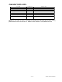
The unit is supplied with a power cord. Should any other connections be required they must be carried
out with the following configuration.
Earth = Green/Yellow cord
Neutral = Blue cord
Live = Brown cord
CONTROL CONNECTIONS
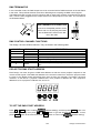
Connection between controller and projector and between one projector and another must be made
with 2 core screened cable, with each core having at least a 0.5mm diameter. Connection to and from
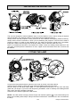
the projector is via cannon 3 pin XLR plugs and sockets which are included with the projector. The
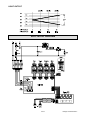
XLR's are connected as shown in the figure above.
Note, care should be taken to ensure that none of the connections touch the body of the plug or each
other. The body of the plug is not connected in any way. The Design 150 accepts digital control
signals in standard DMX512 (1990) format.
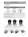
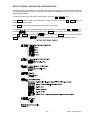
Connect the controller’s output to the first fixture’s input, and connect the first fixture’s output to the
second fixture’s input. The rest may be deduced by analogy. Eventually connect the last fixture’s
output to a DMX terminator as shown in the figure below
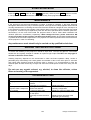
Design 150 uses 3-pin XLR plug / socket. If your controller uses 5-pin XLR plug / socket, you should
convert 5-pin plug / socket into 3-pin socket / plug as shown below.
5/12
Design 150 manual.doc