1
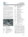
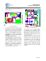
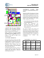
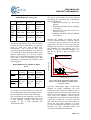
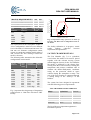
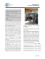
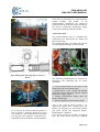
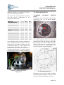
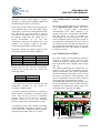
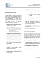
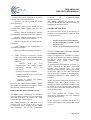
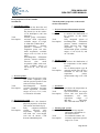
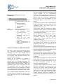
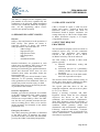
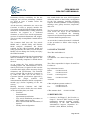
CIRA-UM-04-008
CIRA PWT USER MANUAL
DEPARTMENT
DIPARTIMENTO
PROJECT
PROGETTO
LMSS
NO. OF PAGES
N. PAGINE
JOB
COMMESSA
PWT
ARCHIVE-POSITION
ARCHIVIO-POSIZIONE
***
20
DISTRIBUTION STATEMENT
NATURA DOCUMENTO
30.9024.0000
FILE NAME
PWT UM.DOC
SOFTWARE
MICROSOFT WORD 2000
TITLE
TITOLO
CIRA PWT USER MANUAL
PREPARED
PREPARATO
REVIEWED
VERIFICATO
APPROVED
APPROVATO
AUTHORIZED
AUTORIZZATO
C. Purpura
F. De Filippis
S. Caristia
S. Caristia
EDITOR
E. Trifoni
A. Del Vecchio
DATE/DATA
E. Graps
A. Panico
DATE/DATA
DATE/DATA
DATE/DATA
BY THE TERMS OF THE LAW IN FORCE ON COPYRIGHT, THE REPRODUCTION, DISTRIBUTION OR USE OF
THIS DOCUMENT WITHOUT SPECIFIC WRITTEN AUTHORIZATION IS STRICTLY FORBIDDEN
A NORMA DELLE VIGENTI LEGGI SUI DIRITTI DI AUTORE QUESTO DOCUMENTO E' DI PROPRIETA' CIRA E NON POTRA' ESSERE
UTILIZZATO, RIPRODOTTO O COMUNICATO A TERZI SENZA AUTORIZZAZIONE
I
CIRA-UM-04-008
CIRA PWT USER MANUAL
AUTHORS :
C. PURPURA
TITLE :
CIRA PWT USER MANUAL
ABSTRACT :
The present document describes the characteristics and the procedures of the new CIRA Plasma
Wind Tunnel SCIROCCO. The PWT performance and the main dimension are described. The PWT
auxiliary systems have been described with their mechanical interfaces.
The time schedule requirements and the support requirement have been also outlined in order to
give a guideline to PWT test organization and facility reservation.
Furthermore the CIRA location and nearest lodging options have been presented.
KEYWORDS : Plasma Wind Tunnel, Arc-jet , Hypersonic, Experimental, Instrumentation.
According to the italian law n. 15 of January 4/1968 and, successively revised on July 6/1997, the
undersigning certifies the present copy to be true to the original which remains at your disposal for
inspection.
Place : Capua (CE) - ITALY
Company stamp :
CIRA S.c.p.A.
Date :
Signature :
First name :
Last name :
Position :
____________________________
____________________________
____________________________
____________________________
____________________________
II
CIRA-UM-04-008
CIRA PWT USER MANUAL
REVISION LIST
LISTA DELLE REVISIONI
REV.
0
DESCRIPTION
First Issue
DATE
EDITOR
30.11.2003
C. Purpura
III
CIRA-UM-04-008
CIRA PWT USER MANUAL
SUMMARY
1.0-INTRODUCTION .................................................................................................. 2
2.0-LIST OF ACRONYMS .......................................................................................... 2
3.0-FACILITY DESCRIPTION .................................................................................... 2
4.0-TUNNEL OPERATION ......................................................................................... 4
4.1-SCIROCCO PLASMAWIND TUNNEL: AERO-THERMOFLUIDODYNAMIC PERFORMANCES .. 4
5.0-TEST CHAMBER DETAILS ................................................................................. 6
6.0-ARC HEATER AND NOZZLE SYSTEMS ............................................................ 7
7.0-TEST EQUIPMENTS ............................................................................................ 9
7.1-MODEL SUPPORT SYSTEM (MSS)............................................................................. 9
7.2-CALIBRATION PROBE ARMS (CPA) ....................................................................... 10
8-AUTOMATION SYSTEM ....................................................................................... 10
9-ISTRUMENTATION ............................................................................................... 12
10-TEST GENERAL ARRANGEMENT .................................................................... 14
11-PERSONNEL SAFETY ISSUES ......................................................................... 15
12-CIRA SITE LOGISTIC ......................................................................................... 15
13-PWT TEST REQUEST PROCEDURE................................................................. 15
14-CONTACT POINT ............................................................................................... 16
15-REFERENCES .................................................................................................... 16
Page 1 of 23
CIRA-UM-04-008
CIRA PWT USER MANUAL
1.0-INTRODUCTION
CIRA, the Italian Aerospace Research Centre,
has recently built a 70 MW Plasma Wind
Tunnel, arc-jet kind named SCIROCCO. The
facility primary mission is to simulate the
thermo-fluid-dynamic conditions on Thermal
Protection System of space vehicles reentering the earth atmosphere, on models in
scale 1:1.
The CIRA Plasma Wind Tunnel (PWT)
SCIROCCO is a high enthalpy hypersonic
wind tunnel at the boundaries of state of art
technology. This document describes the wind
tunnel
technical
characteristics
and
performances, its instrumentation and the
typical operative procedures.
The facility is located in Capua (CE), Italy
about 50 km north of Naples. The Plasma
Wind Tunnel is part of a grand new complex
which includes ground testing facilities and
dedicated service utilities making up the Italian
Aerospace Research Centre. The picture in
Fig.1 shows an aerial view of the facility.
GWS Report Generation Workstation
HBDS
High Band Data System
HLAS
High Level Automation System
hmax
Maximum Enthalpy
hmin
Minimum Enthalpy
I
Current
Imax
Maximum Current
LMSS
Space Instruments and Facilities
laboratory
LBDS
Low Band Data System
LCU
Local Control Unit
MCC
Motor Control Center
mmax
Maximum Flowrate
MSDS
Model safety and Failure Mode
Analysis
MSS
Model Support System
OWS Operator Workstation
pmin
Minimum Pressure
Pmax
Maximum Power
PWT
Plasma Wind Tunnel
RWS Requester WorkStation
RTS
Real Time Simulator
SCAS
Supervisory Controls and
Automation System
SDM
Simplified Dynamic model
SDESIM Development System for Simulator
SMSA
Safety Management Sub-Assembly
Test Article
TA
TEWB
Test Engineer’s Work Bench
TAL
Test Automation Language
TC
Test Chamber
UPS
Uninterruptable Power Supply
V
Voltage
3.0-FACILITY DESCRIPTION
Fig. 1: Plasma Wind Tunnel aerial view
2.0-LIST OF ACRONYMS
AC
CPA
DAS
DDM
DeNOx
ENEL
ESA
ESP
FEE
FS
Alternate Current
Calibration Probe Arms
Data Acquisition System
Detailed Dynamc Model
Nitrogen Oxides abatement
National Electrical Energy Agency
European Space Agency
Pressure Scanner Measurement
System
Front End Equipment
File Server
The PWT facility lay-out is shown in Fig.
2.The heart of the facility is the segmented
constricted Arc Heater, a column with a
maximum length of 5.5 m and a bore diameter
of 0.11 m. At the ends of this column there are
the electrodes (cathode and anode) which
generates the electrical arc. The Power Supply
gives the voltage at the electrodes for the
generation of the discharge; it is able to
support direct current up to 9000 A and a total
power up to 70 MW. A Compressed Air
Supply distributes dry air to the various
segments of the arc heater column. It is able to
supply a flow range from 0,1 to 3,5 kg/s with a
total pressure range from 1 to 17 bar. The Arc
Page 2 of 23
CIRA-UM-04-008
CIRA PWT USER MANUAL
Heater column is cooled by circulation of
demineralised water.
CUSTOMER
WORKSHOP
CUSTOMER
WORKSHOP
Argon
System
DeNOx
Diffuser
Cooling
Power
Supply
TEST HALL AREA
Test
Building
PWT ENTRANCE
Heat
Exchanger
Vacuum System
Fig.2: Facility schema
The compressed air injected into the arc heater
is heated up to 10000 K of temperature and
flows through a convergent-divergent Conical
Nozzle increasing the velocity in the Mach
range 6-12. The jet exiting from the nozzle is
confined into a Test Chamber where interacts
with the test article. Then, it is collected in a
long Diffuser (50 m) and cooled by an Heat
Exchanger. The test article is installed on the
Model Support System (MSS).
The last sub-system of the Scirocco facility is
the Vacuum System. It generates the vacuum
conditions required by each test. The system
consists of ejectors that make use of high
pressure water steam as motor fluid (30 bar
and 250°C).Before ejection into the
atmosphere, the process fluid is scrubbed by
chemicals in a subsystem called DeNOx
System to eliminate the Nitrogen Oxides.
The Test Chamber is located into an area
Experimental Hall as shown in Fig.3.
Fig 3: Experimental Hall floor
The facility can use various Conical Nozzles
for
different
test
conditions.
These
interchangeable components are stored inside a
parking area into the Experimental Hall. A
Hoist System for handling of heavy bodies, as
nozzles sections, models, supports etc. is fixed
to the building ceiling.
The main building has the function to host the
operating team, the users offices and the
facility control system room. The control room
is located on the first floor where the
Experimental Hall can be viewed through a
large window. The control room equipment
(see fig. 4) includes the video camera
monitors, the video recording facility, operator
console(s) and the engineering and data
acquisition systems that provide complete
information about the test and model
conditions.
Page 3 of 23
CIRA-UM-04-008
CIRA PWT USER MANUAL
4.1-SCIROCCO
PLASMA
WIND
TUNNEL: aero-thermodynamic performances
The Scirocco PWT facility has been realized to
simulate pressure and temperature to which
earth atmosphere re-entering space vehicles are
exposed. The requirements for Scirocco have
been specified by ESA in terms of pressure and
temperature on the test model stagnation point.
Based on the requirements, two nominal
sample configurations are defined:
TEST HALL AREA
CONTROL ROOM
CUSTOMER OFFICE
Fig. 4: Control room floor
A dedicated large area is also available for
working on the Arc Heater components
(Maintenance Hall) . Three workshop room are
located near the Maintenance Hall for
Instrumentation and Model preparation.
Before a specific test, the selected Conical
Nozzle configuration is installed between the
Arc Heater and Test Chamber. Then the
model is directly installed inside the Test
Chamber on the MSS by means of the
dedicated interface.
• Nose configuration: hemisphere with radius
of 300 or 240 mm and overall dimensions
size of 600x600x600 mm.
• Leading
edge
configuration:
twodimensional hemicylinder with variable
radius and curvature radius at stagnation
point of 100 mm. Overall dimensions size
of 600x600x600 mm.
The required stagnation point pressure and
temperature are relative to three possible reentry trajectories named: nominal, extreme and
safety. They respectively represent a normal, a
extreme, and an emergency trajectory re-entry.
In the following tables there is a synthesis of
required performances to the facility for Nose
Configuration
and
Leading
edge
Configuration.
4.0-TUNNEL OPERATION
The hypersonic plasma-jet usable for the PWT
test achieves Mach numbers depending on the
Conical Nozzle exit diameter. Four nozzle
configurations are available corresponding to
Mach flow values of about 5.1, 6.2, 8.3, 11.5
respectively. Some deviations from the
mentioned values can be observed during a test
due to the variations of the air chemical
composition of the exiting jet.
The Reynolds number per meter is shown to
vary from 10.000 to 160.000, while the flow
velocity varies from 2000 to 6000 m/s,
independent from the used nozzle, as predicted
from the hypersonic theory.
REQUIREMENTS: nose configuration.
Press.
Stagn.
point
Temp.
Stagn.
point
Test
time
Nominal
trajectory
Extreme
trajectory
Safety
trajectory
10÷75
mbar
10÷75
mbar
75÷175
mbar
1300÷1600
ºC
1600÷1700
ºC
1450÷1700
ºC
25 minutes
25 minutes
5 minutes
Page 4 of 23
CIRA-UM-04-008
CIRA PWT USER MANUAL
Extreme
trajectory
Safety
trajectory
5÷25
mbar
5÷25
mbar
15÷100
mbar
1000÷1250
ºC
1200÷1400
ºC
1300÷1600
ºC
25 minutes
25 minutes
5 minutes
The above requirements have been translated
in terms of pressure and heat flux at stagnation
point for both Nose and Leading edge
configuration. This conversion has been
carried out under the hypothesis of a model in
Test Chamber of fully catalytic material, with
thermal conductivity of 7 W/m-K, surface
emissivity of 0.85 and model radius of 300 mm
(nose) and of 100 mm (leading edge). The
transformed requirements are reported in the
following table.
REQUIREMENTS IN TERMS OF HEAT
FLUX
NOSE
Heat flux
Nominal
trajectory
Extreme
trajectory
Safety
trajectory
428÷ 846
kW/m2
846÷1035
kW/m2
612÷1035
kW/m2
230÷380
kW/m2
300÷600
kW/m2
LEADING
EDGE
125÷260
Heat Flux kW/m2
The facility has been designed to satisfy the
ESA requirements; the present design returns a
greater capability as shown in the following.
The Arc Heater has the capability to provide to
the Conical Nozzle air with a total pressure and
a total enthalpy contained into the map
reported in Fig. 5, that represents the
“Performance Map”.
Between the column Arc Heater and the
Nozzle a Plenum Chamber is located, where it
is possible to inject compressed air at ambient
temperature, in order to reduce the total gas
enthalpy. By this way it is possible to reduce
the minimum gas total enthalpy up to 2.5
MJ/kg; in fact, the minimum enthalpy level
that the Arc Heater is able to produce is 10
MJ/kg.
EXPLORED REGION
PREDICTED PERFORMANCES
40
2
Press.
Stagn.
point
Temp.
Stagn.
point
Test
time
Nominal
trajectory
The curves in this figure have been obtained
considering the operating and technological
limits of the facility:
1. Minimum air pressure of 1 bar for arc
stability
2. Maximum allowable total gas enthalpy
of 45 MJ/kg
3. Maximum flow rate from Process Air
System of 3.5 kg/s
4. Minimum allowable total gas enthalpy
of 2.5 MJ/kg
Total Enthalpy, kW/m
REQUIREMENTS: leading edge
30
20
10
0
0
1
2
3
4
5
6
7
8
9
10 11 12 13 14 15 16
Total Pressure, bar
Fig. 5: Theoretical Performance Map (Total
Pressure and Total enthalpy at the inlet of the
convergent nozzle).
From the “Performance Map” an equivalent
diagram of facility capabilities has been
obtained in terms of pressure and heat flux at
stagnation point as function of the model size
and the nozzle configuration. The facility can
work with four different Conical Nozzle
configurations, providing exit nozzle diameters
respectively of 900 mm, 1150 mm, 1350 mm
and 1950 mm. However, the nozzle throat is
always the same with a diameter of 75 mm.
For each configuration an effective exit nozzle
diameter has been calculated taking into
account the boundary layer thickness.
Page 5 of 23
CIRA-UM-04-008
CIRA PWT USER MANUAL
900
1150
1350
1950
900
1050
1200
1500
144
196
256
400
The requirement for the hemispheric model of
“Nose configuration” must have two different
sizes with radius of 300 mm and 240 mm. The
900 mm exit diameter configuration cannot
operate in conjunction with the model radius of
300, because the flow blockage around the
model is foreseen.
The following table summarizes the allowable
configurations nozzle/model:
Nozzle exit Area
diameter
ratio
A/A•
mm
144
900
196
1150
196
1150
196
1150
256
1350
256
1350
256
1350
400
1950
400
1950
400
1950
Configur.
Nose
Nose
Nose
Lead. edge
Nose
Nose
Lead. edge
Nose
Nose
Lead. edge
Model
radius
mm
240
240
300
100
240
300
100
240
300
100
Fig. 6 represents the design maps of Stagnation
point Pressure vs. Heat Flux of Scirocco PWT
facility.
EXPLORED REGION
PREDICTED PERFORMANCES
1400
2
1200
Stagnation Heat-Flux, kW/m
PROCESS REQUIREMENTS min max
Air mass flow (kg/sec)
0,10 3,5
Air enthalpy content (MJ/kg)
2,50 45
Air operative pressure (mbar)
0,01 2,9
Exit
Effective
exit Area ratio
diameter
diameter
A/A•
mm
mm
1000
800
600
400
200
0
1
10
100
1000
Stagnation Pressure, mbar
Fig. 6: Performance map of Scirocco in terms of
Pressure and Heat Flux at Stagnation Point on
the model.
The facility calibration is in progress. Actual
results
indicate
coherence
between
experiments and predictions.
5.0-TEST CHAMBER DETAILS
The Test Chamber (fig. 7) is a cylindrical
vessel where the model to be tested is placed
together with the relevant moving system
(Model Support System). In the Test Chamber
the model is impacted by the plasma flow
coming from the Conical Nozzle, reaching the
temperature and pressure conditions able to
simulate the thermo-fluidynamic conditions
acting on the protection shield of space
vehicles during the atmosphere re-entry. The
exit of the Test Chamber is connected through
a mating flange to the “Pick-Up” of the
Diffuser.
The system has been designed in agreement
with the following process requirements.
TEST CHAMBER CHARACTERISTICS
Shape
Cylindrical
Vertical
Overall Size
height
inner diameter
9217 mm
5170 mm
Material
Steel
Fe 510
The list of the most important equipment is
hereinafter reported:
Page 6 of 23
CIRA-UM-04-008
CIRA PWT USER MANUAL
1. Openings to allow access for personnel to
enter the model, and for maintenance.
2. Windows to
allow the plasma
flow
monitoring.
3. Retractable floor (two sections).
4. System to inject process air (bleed air
system).
5. Air flow system.
In the Test Chamber some systems are
foreseen to allow the correct model positioning
in the plasma flow (MSS), to measure the
plasma characteristics (Calibration Probes)
and to facilitate the maintenance operations on
the Model (Retractable Floor).
During the PWT operative phase the plasma
flow, after having impacted the model, is
driven toward the Diffuser “pick up” section.
In the case of particular test conditions, it is
foreseen the possibility to inject in the Test
Chamber a small process air stream (through
the “bleed air system”) in order to increase the
static pressure in the test chamber and facilitate
the flow driving in the pick up section of the
Diffuser, in order to have a less severe
Vacuum System operations.
After each test, before allowing personnel
access,
re-pressurization,
air
washing
operations and internal air characterisation are
performed.
The system air washing phase starts with cold
dry process air, that continues to be supplied to
the Arc Heater after the end of the test, and
continues with atmospheric air that is sucked
in by the fan.
After few minutes from the beginning of the
air washing phase, a fan is activated. A small
mass flow of internal Test Chamber air is sent
to an analyser to measure the content of O2,O3
and H; only when the level of the monitored
gases is under the prescribed limits, the
managing LCU2 ends the washing operation
and allows the personnel access in the system.
Fig. 7: Test Chamber
6.0-ARC HEATER
SYSTEMS
AND
NOZZLE
The arc heater is located in the Test Hall
between the Compressed Air System and the
Conical Nozzle.
The arc heater is shown in fig. 8 through 10,
and it is the generator of high temperature air
(Plasma) necessary to simulate aerothermal
flight condition of re-entry vehicles. The
increase of temperature (10000 K) of the
incoming process air takes place through the
transformation of electric energy into thermal
and kinetic energy) by means of an electric arc
discharge between the electrodes. The gas,
after being heated in the arc heater, is
accelerated through the nozzle where the gas
thermal energy is converted in kinetic energy.
The arc heater has been designed in according
to the following process data:
Air pressure (Bar)
Air mass flow rate (Kg/sec)
Plasma enthalpy -(MJ/kg)
Electric power -(MW)
Direct current (Ampere)
Voltage (Volt)
MIN.
MAX.
1,0
0,1
2,5
1,0
1000,0
1000,0
16,7
3,5
45,0
70,0
9000,0
30000,0
Page 7 of 23
CIRA-UM-04-008
CIRA PWT USER MANUAL
coils, helps to position the arc on the electrode
surface rapidly, and thanks to an
electromagnetic mechanism, the interaction
point between the electrode surface and the arc
foot moves continuously minimising copper
erosion and extending electrode lifetime.
3) Plenum section
Fig.8: Arc Heater components
Fig.9: Photographs and design draws of the Arc
Heater
The plenum chamber (fig. 11) constitutes the
connection piece between the arc heater and
the conical nozzle.
The plenum function is to reduce the process
air total enthalpy through cold air injection.
Fig. 11: Plenum chamber and nozzle throat
The following instrumentation is foreseen for
monitoring and controlling the arc heater
operation:
• Current measurement on each power cable
connected to the arc electrode rings;
• Measurement of the voltage fluctuations
generated between the anode and the cathode
main power supply cables;
• Voltage measurement among some arc
heater column rings;
• Plenum chamber pressure measurement;
Fig. 10: Typical segment pack
It is necessary to point out that the ignition of
the arc heater is with the injection of argon
only. Moreover, the combination of argon (air)
gas injection and magnetic rotational force,
generated by the current flow into the magnetic
Aim of the Conical Nozzle System is to
expand the plasma flow coming from Arc
Heater for increasing its speed and simulate
into PWT facility the requested thermofluidodynamic conditions.
Four conical nozzles are available, all of them
have the same throat and seven different
Page 8 of 23
CIRA-UM-04-008
CIRA PWT USER MANUAL
expansion sections are connected in such a
way to return the required nozzle.
This system has been designed in agreement
with the process requirements at the
component battery limits:
PROCESS
REQUIREMENTS
min
max
Air mass flow (kg/sec)
0,1
3,5
Enthalpy
(MJ/kg)
2,5
45,0
air
content inlet
Air pressure (bar)
Air pressure (mbar)
inlet
outlet
1,0
0.01
16,7
2.9
Air speed (m/s)
inlet
outlet
120
2000
350
7000
The combination of the operative conditions as
above reported, permits to obtain on the test
model surface the required conditions in terms
of Heat Flux (from 125 to 1035 KW/m2) and
Stagnation Pressure (from 5 to 175 mbar)
On the device, instruments for monitoring are
installed. Measurement of plasma pressure
corresponding to nozzle exit has been foreseen.
Fig. 12: Conical nozzle mounted into Test
Chamber (1150 mm exit diameter
configuration).
7.0-TEST EQUIPMENTS
7.1-MODEL
(MSS)
SUPPORT
SYSTEM
The model to test is interfaced to an automated
cooled arm (fig. 13), the Model Support
System (MSS).
Fig. 13: Model Support System
The model mechanical interface with MSS,
generally realized by the customer, is through a
plane flange φ 304 mm with eight M12 plane
holes at φ 240 mm; the corresponding flange
on MSS side (fig. 14) is provided of two
reference pin holes for clocking purpose.
Fig. 14: MSS Interface flange
Maximum overall model weight (including
instrumentations and cables) is 1650 N, center
of gravity lying on MSS flange center line.
Page 9 of 23
CIRA-UM-04-008
CIRA PWT USER MANUAL
Maximum overall model length in plasma
direction, i.e. between the stagnation point and
the MSS interface plane, is 1010 mm.
Before the test, the model is located under the
Test Chamber floor level. The MSS flange
center line is 1650 mm far from plasma center
line. During the test, the model is injected
vertically in the plasma flow; once achieved
the plasma center line, the model can be
moved horizontally up to 750 mm
downstream, respect to the plasma flow, and
pitched ± 20° around a center of curvature
1010 mm upstream MSS interface plane.
During the motion, the model is subject to the
following maximum kinematic conditions
7.2-CALIBRATION
(CPA)
PROBE
ARMS
In the Test Chamber there are two calibration
arm (Calibration Probes Arms). Also these
arms
are
cooled
using
pressurised
demineralized water. Their function is to
support and locate measurement instruments
into the plasma in order to measure its
characteristics in several positions. The arms
of the Calibration Probes can rotate around an
axis, parallel to the plasma flow axis, and can
be located in such a way that the center-line of
the installed instrumentation can coincide with
the plasma flow axis. The motion is actuated
by electrical motors.
8-AUTOMATION SYSTEM
Vertical
Horizontal
Angular
Speed
Acceleration
± 0.6 m/s
± 0.2 m/s
± 4 °/s
± 3.0 m/s2
± 1.9 m/s2
± 40 °/s2
During the test, the expected aerodynamic
loads on the model must not exceed the
following values:
Drag
Lift
Lateral
5330 N
± 800 N
± 533 N
A maximum of 160 pressure channels and 100
temperature channels for the model are
available at MSS interface.
A cooling system for the model is available at
MSS interface, providing a maximum demi
water flow rate of 18 m3/h at a maximum
pressure inlet of 38 barg and at a minimum
pressure outlet of 8 barg; the minimum
pressure outlet can be increased up to 15 barg .
The PWT Control and Automation System is
realised in different levels, and the Data
Acquisition System is integrated in it assuring
the experimental data sampling and storage
(fig. 15).
The facility instruments are divided into two
categories: the control instruments and the
process instruments. The control instruments
are those installed in the facility, used to verify
the proper operation of each subsystem. The
process instruments are those whose acquired
data are used as experimental test results.
An independent supervisor system verifies that
the all parameters of the facility operating
conditions are within their safety ranges and
each subsystem is properly operating.
HLAS
SCAS-SIM
TEWB
HLAS-GWS
PRINT
SERVER
AIS Mngm. Link
HLAS-RWS
HLAS-OWS
PRINT
SERVER
SCAS
SDESIM-WS
HLAS-FS
PWT Process Control Link
ESP
DAS
HBDS
LBDS
LCU 1
LCU 3
LCU 2
LCU 5
LCU 4
LCU 7
LCU 6
LCU-EWS
LCU-OWS
An electrical system for the model is available
at MSS interface, consisting in a 500 W – 220
VAC cable with 3 conductors (phase, neutral,
ground) and a ground cable (S = 16 mm2).
PRESSURE
TRANSD.
PRESSURE
TRANSD.
THERMOCOUPLES
THERMO
CAMERAS
CALORIMETERS
POSITIONER
VIDEO
CAMERAS
SPECTRORAD. (opt.)
SPECTROSCOPE (opt.)
CONVENTIONAL
TEST INSTR.
SCHLIEREN
SYS. (opt.)
VIRTUAL TEST INSTR.
LCU
PLASMA HEAT EX.
PYROMETER
CONICAL NOZZLE
SAFETY S/S
VACUUM & STEAM
DENOX & OSMOSIS
MODEL SUPPORT
TEST CHAMBER
POWER SUPPLY
DIFFUSER
ARC HEATER
COOLING SYS.
COMPRESSED AIR
ARGON SYSTEM
ELECTRICAL SYS.
SAFETY
FIELD
INSTRUM.
PWT SUBSYSTEM
Fig. 15: Automation System scheme
Page 10 of 23
CIRA-UM-04-008
CIRA PWT USER MANUAL
The building blocks of the PWT Automation
and Instrumentation Systems are:
−
High level automation system
The
High-Level
Automation
System
encompasses all the computing and display
resources needed to perform the control of the
PWT at level 3, i.e. test conduction, control of
the overall facility, exploiting data acquired by
Test Instrumentation (via DAS), to fix
operating parameters of the Control System
(LCU).
- File Server (FS), which acts as a “general
repository” of all the HLAS data, including:
•
data prepared by the Test Engineers
using the TEWB
•
data acquired by the LBDS
- Test Engineer’s WorkBench (TEWB), a
SW development environment to allow the
preparation of the Automated Test
Procedures (written in Test Automation
Language, TAL) and of the I/O Tables for a
specific test session.
- HLAS Operator Workstation (OWS),
which is the main MMI of the system and
allows both to examine in real-time a
selected subset of the acquired data and to
issue automation control commands for the
test conduction.
- HLAS Requester Workstation (RWS),
allowing to examine in real-time a selected
subset of the acquired data but without the
possibility to issue automation control
commands (customer W.S.).
•
Simplified
(SDM)
•
Detailed
(DDM)
•
Real-Time Simulator (RTS)
Dynamic
Dynamic
Model
Model
The first 2 SW packages (SDM and DDM)
can be used for the definition of the test
parameters to be used in next test
campaigns, while the RTS is aimed to
allow the functional validation of
Automated Test Procedures before their
actual execution on the SCAS.
The
HLAS
includes
the
following
computers/workstations equipments:
- Supervisory Control and Automation
System (SCAS), on which are executed the
Automated Test Procedures.
SW Development System for Simulator
(SDESIM), on which the following main
SW packages can be executed:
−
SCAS Simulator (SCAS-SIM), interfaced
to the RTS for the execution of real-time
test simulations.
−
Peripherals and LAN items
Data Acquisition System (DAS)
The Data Acquisition System encompasses all
the HW and SW equipment needed to acquire
real-time measurement data from the Test
Instrumentation and field devices, store them
for further post-processing and (in case of
LBDS) transmit them in real-time to HLAS to
allow the control of the PWT at level 3.
The HLAS can be further divided in:
− Low-Bandwidth Data Acquisition System
− High-Bandwidth Data Acquisition System
Low-bandwidth data acquisition system
The LBDS system shall be composed by two
main items connected via TCP/IP LAN:
- HLAS Report Generation Workstation
(GWS), dedicated to the post-processing of
the data acquired in real-time during a test
execution session.
Page 11 of 23
CIRA-UM-04-008
CIRA PWT USER MANUAL
1. LBDS Workstation (LBDS-WS), in charge
to perform the following functions:
- interface with the Operator for standalone operations
Computer
for
Commands/Events
acquisition/sending.
The HBDS computer is located in the
Computer Room and the HBDS front-end is
located in the Electronic Room.
- interface with the File Server for I/O
Configuration Tables loading and test data
archiving
9-ISTRUMENTATION
- interface with the Automation Computer
for commands acquisition and events emission
The Scirocco PWT facility is provided by an
extended Test instrumentation supply in order
to fully characterise
- interface with the Automation Computer
for parameters sending and acquisition
- interface with the FEE for set-up and data
acquisition
- data calibration and transmission to
Automation Computer
- support to calibration tables preparation
2.
LBDS Front-End Equipment (LBDSFEE), also called "Measurement FrontEnd", in charge to perform the following
functions:
interface
with
the
Test
Instrumentation for analog signals
acquisition,
filtering
and
A/D
conversion
- handling of spare I/O channels
- interface with the WS for set-up and
data transmission
- support to sensors and channel
calibration operations
Moreover, the LBDS supply includes a IEEE488 controlled instrument to support sensors
and channels calibration operations.
High-bandwidth data acquisition system
The HBDS system is consisting of a Pentiumbased Personal Computer and a measurement
front-end dedicated to acquire the input
signals from the Facility devices.
The HBDS computer is connected via a
TCP/IP LAN to the File Server for I/O
Configuration Tables loading and for HBDS
data archiving, and to the Automation
•
•
•
the flow properties in Test Chamber,
the thermodynamic properties on the
model surface,
the flow properties along the Test Leg
in terms of temperature, pressure, heat-flux
and chemical composition.
CIRA test engineers are available for support
and data interpretation. Nevertheless customers
are free to operate, within their individual
agreement
with
CIRA,
their
own
instrumentation.
To perform these measurements, real time (i.e.
directly managed by the Data Acquisition
System) and non-real time (i.e. fully
independent measurement system) instruments
are foreseen. There are also some instruments
able to follow the “dynamic re-entry trajectory
simulations” that Scirocco PWT would be able
to realize.
All the instruments positioned outside the Test
Chamber, near the optical accesses, are
mounted on remote controlled positioners, able
to follow the model displacements along the
flow axis and to focus the measurement region
on the model surface.
Two video cameras are available. They
monitor the phenomena into Test Chamber
during all the test phases.
In the following a detailed functional and
technical description of the various instruments
is given:
Page 12 of 23
CIRA-UM-04-008
CIRA PWT USER MANUAL
Flow properties in Test Chamber
instruments
• Calorimetric probes
Function:
to measure the heat flux and
pressure distribution of the of
the plasma jet on the surface
of an hemisphere (100 mm
diameter).
Tech.
Gardon gauge calorimeters,
Description:
real-time mode acquisition,
available ranges of 0÷500,
0÷1000 and 0÷3000 kW/m2.
Interchangeable
absolute
pressure
transducer
on
stagnation point, real time
mode acquisition, available
ranges of 0÷35, 0÷86, 0÷220
mbar.
Interchangeable differential
pressure scanner transducer,
non-real
time
mode
acquisition (ESP) with seven
ports, available ranges of
±0÷25,±0÷70, and ±0÷350
mbar.
• Pressure probes
Function:
to measure the pressure at the
test model stagnation point
and the pressure profile in the
transversal flow direction
Tech.
Interchangeable
absolute
Description:
pressure transducer, real time
mode acquisition, available
ranges of 0÷8.6, 0÷35, 0÷86,
0÷140 and 0÷220 mbar.
• Spectroscopic system
Function:
to characterise the chemicalphysical properties of the flow
(free-stream and shock-layer)
Tech.
Fully
computer-controlled
Description:
system,
non-real
time
acquisition, spectral range
190÷1200 nm wave-length,
scan rate 45 nm/sec, CCD
detector 2000x800 pixels.
Thermodynamic properties on the model
surface instruments
• Pressure Scanner Measurement System
(ESP)
Function:
to measure the distribution of
the pressure on the model
surface.
Tech.
Fully integrated system of
Description:
interchangeable
differential
pressure scanner transducers
(ESP), non-real time mode
acquisition,
up
to
200
measurement points, available
ranges of ±0÷25,±0÷70, and
±0÷350 mbar.,
• Thermocouples
Function:
to measure the distribution of
the temperature on the model
surfaces.
Tech.
Set of thermocouples type B
Description:
(max 40) and K (max 60) for a
maximum of 100 real time
acquisition
points,
measurement range of 0÷1750
°C.
• Pyrometers
Function:
to measure the temperature on
the model surfaces.
Tech.
Spot measurement, two single
Description:
colour and two dual-wave
instruments,
real
time
acquisition,
ranges
of
400÷800,
600÷1000,
700÷1400 and 1000÷3000 ºC.
• Thermograph systems
Function:
to quantitatively map the
temperature distribution on
the model surfaces.
Tech.
Two infrared scanners, noDescription:
real time acquisition, spectral
range of 8÷12 µm.
Page 13 of 23
CIRA-UM-04-008
CIRA PWT USER MANUAL
Flow properties along the Test Leg
instruments
• Static pressure measurement system
Function:
to measure the static pressure
in various points of the test
leg:
1. Plenum Chamber
2. Conical nozzle exit
3. Test Chamber
4. Diffuser
Tech.
Absolute pressure transducers,
Description:
real time acquisition:
1. Two transducers, range
0÷5.5 and 0÷22 bar
2. Two
set
of
four
transducers, range 0÷2 or
0÷10 mbar
3. Two
set
of
four
transducers, range 0÷2 or
0÷10 mbar
4. Sixteen transducers, 8 of
range 0÷10 mbar and 8 of
0÷100 mbar
10-TEST GENERAL ARRANGEMENT
The Scirocco PWT facility have been designed
for a 3runs/day, 10runs/week, 250runs/year
maximum test rate. The currently proven
testing capability is 1run/day, 3runs/week on a
8 hour single shift, although 2runs/day rates
have been also performed.
Several on site activities are required to
accomplish the tests on Customers Test
Articles (TA): TA incoming inspection, TA
instrumentation and mechanical interfacing on
facility Model Support System (MSS), TA
installation checks, test(s) execution, post test
TA inspection. The two latter tasks are
repeated, in case of a test campaign on a single
TA. At the end of the testing activities the TA
is dismounted and disconnected from the MSS.
Two separate Model Preparation Area are
available to allow Customer(s) activities on TA
before and after the test (or test campaign)
execution.
The time required for the TA installation and
checks, depends on its instrumetation
complexity, meaning both sensors number and
types. For a not instrumented model 4 hour is
typical, while for a “heavely” instrumented
model 3 days could be required. For the
dismounting phase a mean time 1 day is
typical.
If required, pyrometers and/or thermocamera
setting and pointing activities follow the TA
installation phase. This task takes one
additional work day (typ.).
All the above tasks are performed by LMSS
technicians, on the basis of Customer official
Test Article installaltion data, with Customer
on site Engineer assistance.
The test execution is comprehensive of three
phases: facililty start up (3 hour typ.),
experiment conduction (can be repeated
several times), facility shut down to safe
condition (2 hour typ.).
Customer on site Engineer is allowed to stay in
the Control Room during the experiment
conduction phase only (i.e. when the TA is
injected into the plasma).
After each test, data are collected and stored on
the Data Acquisition System File Server. Then
the most important (facility and model) rough
data are printed for first evaluations.
Official test report is issued within 30 working
days after the test campaign conclusion. The
format is both on paper and electronic format
(CDROM).
Three types of meeting are foreseen between
LMSS and Customer’s Team, during the on
site activities: a) a preparation meeting, b) one
(or more) intermediate meeting, c) a test
campaign conclusion meeting.
Typically LMSS supplies the Customer all the
necessary information to interface the Test
Article to the facility (both mechanical and
instrumental interface). On request the LMSS
Team can size and supply the Model Holder
and mount it on the Test Article. The time
required depends on the test condition, TA
structure and instrumentation. Typical time is 3
months.
Page 14 of 23
CIRA-UM-04-008
CIRA PWT USER MANUAL
The PWT is charged on the occupancy time
plus number of tests basis, regardless the test
condition(s) to be achieved. Model installation
activities are considered within the occupancy
time. All the engineering and/or service
activities are quoted separately.
11-PERSONNEL SAFETY ISSUES
Hazards
Safety is first and foremost in the operation of
PWT facility. The plasma arc heater is
especially sensitive to proper and prudent
safety procedures. The main risks are:
lethal voltage,
high-pressure gas,
high-pressure water,
high temperature,
noise,
mechanical hazards.
Detailed indications are positioned in each
critical area, nevertheless, PWT users are not
allowed to operate any plant components.
During pre-run briefing, the potential hazard is
shown and discussed. PWT users are also
informed about safety procedures before the
test program start.
This facility may pose serious hazards if strict
adherence to all operating instructions and
safety guidelines are not maintained. Failure to
comply may result in serious injury or death.
The facility must never be operated in presence
of personnel in the test hall.
Protective Equipments
Hardhat, eyes and ears protection are available
in the PWT Maintenance Hall. Other personal
equipment needed for model workshop
activities are not provided by CIRA. The PWT
user has his own personal protection devices
such as working gloves, shoes, to be used for
model mounting and assembly in the model
preparation area.
Emergency Procedures
The CIRA emergency procedure is illustrated
to the PWT users. If required, all people
present in the PWT area follow the instructions
given by the CIRA Team Safety Responsible .
12-CIRA SITE LOGISTIC
CIRA is located in Capua, a small city near
Naples and Caserta, located at about 200
kilometers south of Rome and about 50
Kilometers North of Naples. Customers can
arrange their trip to CIRA with a flight either
to Rome (Fiumicino Airport) or to Naples
(Capodichino Airport).
13-PWT TEST REQUEST
PROCEDURE
The hereinafter description will be focussed on
technical aspects only. All the contractual
activities, steps definitions and timings
relevant to the request to test at PWTSCIROCCO facility will not be adressed.
The TPS testing is divided in three main
phases, typically:
a) materials identification, testing and
selection
b) realization and test of a preliminary
(dummy) model, rated 1:N respect the
real object
c) realization and test of the final model,
rated 1:N respect the real object
The Scirocco PWT can be used for testing in
all the above three phases, although for phase
a) a small arc-jet facility is more suitable.
The typical path that drives to the test
campaign completion, relevant to above phase
b) or c), is as follows:
During a meeting, Customer and PWT
Engineers discuss about the test campaign
objectives, the device to test, the test
conditions and measurement requirements.
Then PWT Engineers verify the feasibility of
the test campaign, on the basis of the given test
condition, Model geometry (shape and
dimensions) and measurements requirements.
Following technical discussion, Customer
issues the agreed test matrix as well as the Test
Article characteristics, instrumentation and
data analysis requirements.
Page 15 of 23
CIRA-UM-04-008
CIRA PWT USER MANUAL
Preliminary Facility availability for the test
campaign and relevant preliminary schedule
are fixed at least 6 months before the
beginning of tests.
All the necessary information are sent to the
Customer in order to properly interface the
Test Article with PWT Model Support System:
mechanical, instrumentation, cooling, electrical
interfaces are reported in a dedicated
document, as well as Test Article requirements
in terms of maximum dimensions and weights.
This is typically accomplished 6 months before
the tests.
The Customer shall issue the Test Article
MSDS and a “Model Safety and Faiulure
Mode Analysis” documents, the former
required for the CIRA Personnel health and
safety precautions, the latter to assure that the
Model will not damage the Facility nor injury
the CIRA Personnel.
Furthermore the Model design documentation
shall be submitted to CIRA for approval. The
above is normally completed 3 months before
the tests.
As an option the Test Article realization,
including holder and instrumentation, can be
done by PWT team, if required. In this case the
Customer shall supply all the necessary design
documents and specifications. The materials
can be selected and provided by Customer or
by CIRA, the latter case on the basis of
Customer detailed specifications approved by
CIRA.
The
design,
material
and
instrumentation definition shall be completed 6
months (typ.) before beginning of the test
activity.
Meeting between Customer and PWT
Engineers are held to define the tests details.
At the end of this phase, are fixed:
-
Test Plan
Instrumentation
requirements/specification
Test Article installation procedures on
PWT model support system
Data collection and data elaboration, if
required
Facility main configuration
One month before the tests, PWT Engineers
define the details of the Facility configuration
for the Test campaign, including auxiliaries
requests. Detailed schedule is issued reporting
meetings, runs, gallery activities, inspections,
and so on.
The Test Article arrival on site is requested one
week before the begin of the installation
activities, to accomplish the incoming
inspection and formal trasportation to the PWT
Customer Model Preparation Area.
At arrival the Customer Personnel is informed
on the procedure to follow when staying at
PWT plant.
14-CONTACT POINT
The CIRA mail address is:
CIRA scpa
Via Maiorise s.n.c.81043 Capua (CE)
ITALY
The CIRA responsible for Space Ground Test
Facilities is:
Ing. Sebastiano Caristia
Phone:
+39-0823-623921
Fax :
+39-0823-633947
E-mail:
[email protected]
Phone
+39-0823-623400
Assistant
CIRA telephone operator number is:
+39-0823-623111
Fax :
+39-0823-969272
CIRA entrance desk: +39-0823-623001
15-REFERENCES
1. Caristia S., De Filippis F., Del Vecchio A.,
Graps E. “Scirocco PWT Facility for high
temperature material assembly testing”,
Proceedings of the 54th International
Astronautical Congress, September 29 –
October 3,2003, Bremen, Germany
Page 16 of 23
CIRA-UM-04-008
CIRA PWT USER MANUAL
2. De Filippis F., Caristia S., Del Vecchio A.,
Purpura C. “The Scirocco PWT facility
calibration activities”, Proceedings of the
3rd
International
Symposium
on
Atmospheric re-entry vehicles and systems,
Arcachon (F), 24-27 March, 2003.
3. Caristia S., De Filippis F.,Del Vecchio A.,
Purpura C. “Scirocco final tests measured
data: comparison between theory and
experiments”, Proceedings 4th European
Symposium on Aerothermodynamic for
Space Applications, 15-18 Oct. 2001,
capua, Italy, ESA SP-487, March 2002.
4. Caristia S., De Filippis F., Del Vecchio A.
“Scirocco facility: qualification phase”,
Proceedings of the 2nd International
Symposium on Atmospheric re-entry
vehicles and systems, Arcachon (F), 26-29
March 2001.
5. Caristia S., De Filippis F., Del Vecchio A.
“Scirocco project: start-up phase” 51st
International Astronautical Congress, Rio
de Janeiro, Brazil, 2-6 Oct 2000.
Page 17 of 23