1
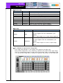
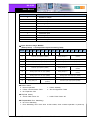
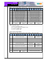
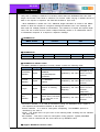
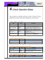
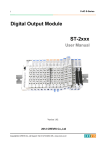
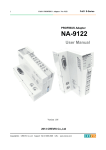
NA-9189
User Manual
Copyright(C) * CREVIS Co.,Ltd * Support +82-31-273-6452 * URL : www.crevis.co.kr
-1-
NA-9189
User Manual
List of Revisions
No.
1
Date
2007.12.15
Version
1.00
Revision
Created
Copyright(C) * CREVIS Co.,Ltd * Support +82-31-273-6452 * URL : www.crevis.co.kr
-2-
NA-9189
User Manual
Contents
1. Product Specification
1) General Specifications
2) MODUBS/TCP Communication Specification
2. MODBUS Setting
1) Communication parameter setting
2) I/O allocation
3) MODBUS/TCP Interface
3. DeviceNet Network Installation
1) MODBUS/TCP Electrical Interface
4. Check Operation Status
1)
2)
3)
4)
5)
MOD : Module Status LED
LINK : Physical Connection LED
ACTIVE : Exchange Data/Traffic Present LED
I/O : Expansion Module Status LED
Field Power : Field Power Status LED
Copyright(C) * CREVIS Co.,Ltd * Support +82-31-273-6452 * URL : www.crevis.co.kr
-3-
NA-9189
User Manual
1) General Specifications
Item
Temperature
Humidity
Specifications
Operating
-0℃ to +60℃ (32℉ to 140℉)
Storage
-40℃ to +85℃ (-40℉ to 185℉)
Operating
5 to 95% RH (Non-condensing)
Storage
5 to 95% RH (Non-condensing)
Vibration immunity
10 TO 55Hz,double amplitude of 0.75mm,
10minutes on each of 3 axes (X,Y,Z)
Shock Immunity
Peak acceleration and duration 15g/11ms, 3 times
on each of 3 axes (X,Y,Z)
Capsuling
Din rail or screw tightening
Remarks
2) MODBUS/TCP Communication Specification
Item
Specification
Network Protocol
MODBUS TCP, HTTP, BOOTP, 16 TCP
Connection
Network length
Up to 100m from Ethernet Hub/Switch with twisted
CAT 3 UTP/STP
Number of Nodes
Limited by Ethernet Specification
Communication speed
10/100Mbps, Auto-negotiation, Full duplex
Number of Expansion I/O
Max. 32 Slots
Interface Connector
RJ-45 socket
Indicator
5LEDS
1Green/Red, Module Status (MOD)
1Green,Physical Connection (LINK)
1Green,Exchange Data/Traffic Present (ACTIVE)
1Green/Red, Expansion Module Status (I/O)
1Green,Field Power Status
System Power
Supply voltage : 24Vdc nominal
Supply voltage range : 11~28.8Vdc
Protection : Output current limit (Min.1.5A)
Reverse polarity protection
Isolation
System power to internal logic : Non-isolation
System power to I/O Driver : Isolation
Copyright(C) * CREVIS Co.,Ltd * Support +82-31-273-6452 * URL : www.crevis.co.kr
Remarks
-4-
NA-9189
User Manual
MODBUS setting include the following configurations:
-
IP-Address Setup using ARP
IP-Address Setup using BOOTP
I/O allocation
MODBUS/TCP Interface
1) Communication Parameter Setting
◆ IP-Address Setup ARP
A way to change the adapter IP address could be applied using such as Command
Windows (only applicable same subnet).
DOS Prompt
>ping 192.168.123.236 // current IP address
>arp -a // view Ethernet physical address
>arp -d 192.168.123.236 // Delete arp table
>arp -s 192.168.123.237 00-14-F7-00-00-00 // assign static arp table with new IP address
//"00-14-F7-00-00-00" is Ethernet Address (See Adapter Label)
>ping -n1 -l 741 192.168.123.237 // assign new IP address
>arp -d* //clear all arp table
>ping 192.168.123.237 // Check response of adapter new IP address
After IP-Address setup using ARP.
IP Address = 192.168.123.237
Subnet Mask = 255.255.255.0
Gateway = 192.168.123.254
◆ IP-Address Setup using BOOTP
If the adapter BOOTP enable, the adapter sends BOOTP request message of 20 times
every 5sec.
The following is an example of adapter IP-Address setup that can be used with a third party
BOOTP sever.
Copyright(C) * CREVIS Co.,Ltd * Support +82-31-273-6452 * URL : www.crevis.co.kr
-5-
NA-9189
User Manual
◆ Communication Speed Setting
- See Master Setting about communication speed setting. (Auto-negotiation, Full duplex)
2) I/0 Allocation
An expansion module may have 3 types of data as I/O data, configuration parameter and
memory resister. The data exchange between network adapter and expansion modules is
done via an I/O process image data by FnBus protocol. The following figure shows the
data flow of process image between network adapter and expansion modules.
Copyright(C) * CREVIS Co.,Ltd * Support +82-31-273-6452 * URL : www.crevis.co.kr
-6-
NA-9189
User Manual
◆ Resister Map
Start Address
Read/Write
Description
0x0000
Read
Process Input image resisters
0x0800
Read/Write
Process output image registers
0x1000*
Read
Adapter Identification special registers.
0x1020*
Read/Write
Adapter Watchdog, other time special register.
0x1040*
Read/Write
Adapter TCP/IP special register.
0x1100*
Read/Write
Adapter Information special registers.
0x2000*
Read/Write
Expansion Slot Information Special registers
*The special register map must be accessed by read/write of every each address (one address)
◆ Bit Map
Start Address
Read/Write
Description
Process input image bits
0x0000
Read
All input registers area are addressable by bit
address.
Size of input image bit is of input image register*16.
Process output image bits
All output registers area are addressable by bit
0x1000
Read/Write
address.
Size of output image bit is size of output image
register
◆ For Example of Input Process Image Data
Input image data depends on slot position and expansion slot data type.
Input process image data is only ordered by expansion slot position when input image
mode is uncompressed (mode 0,2). But, When input image mode is compressed (mode
1,3), input process image data is ordered by expansion slot position and slot data type.
Copyright(C) * CREVIS Co.,Ltd * Support +82-31-273-6452 * URL : www.crevis.co.kr
-7-
NA-9189
User Manual
Slot Address
Module Description
0
MODBUS Adaptor
1
4-Discrete input
2
8-Discrete input
3
2-Analog input
4
16-Discrete input
5
4-Discrete input
6
8-Discrete input
7
4-Discrete input
8
2-Analog input
9
16-Discrete input
10
4-Discrete input
◆ Input Process Image Mode#0
(Status(1word) + Uncompressed Input Processing Data)
WORD#
#15
#14
#13
#12
#11
#10
#9
#8
#7
+0
EW
0
0
0
0
0
0
0
FP
#5
#4
#3
#2
#1
#0
FnBUS Status
Discrete Input 8points (slot#2)
+2
Analog Input CH0 High byte (slot#3)
Analog Input CH0 low byte (slot#3)
+3
Analog Input CH1 High byte (slot#3)
Analog Input CH1 low byte (slot#3)
+4
Discrete Input high 8points (slot#4)
Discrete Input low 8points (slot#4)
+5
Discrete Input 8points (slot#6)
Empty,Always 0
Discrete Input 4points
(slot#5)
+6
Analog Input CH0 low byte (slot#8)
Empty,Always 0
Discrete Input 4points
(slot#7)
+7
Analog Input CH1 low byte (slot#8)
Analog Input CH0 high byte (slot#8)
+8
Discrete Input low 8points (slot#9)
Analog Input CH1 high byte (slot#8)
Empty,Always 0
Discrete Input 4points
(slot#10)
FnBus Status:
: Normal Operation
: FnBus Communication Fault
: No Expansion Slot
● FP(Field Power)
0 : 24Vdc Field Power On.
Empty,Always 0
Discrete Input 4points
(slot#1)
+1
+9
●
0
2
4
#6
Discrete Input high 8points (slot#9)
1 : FnBus Standby
3 : Slot Configuration Failed
1 : 24Vdc Field Power Off
● EW(MODBUS Error Watchdog)
0 : No Error Watchdog
1 : Error Watchdog once more since its last restart, clear counters operation or power-up.
Copyright(C) * CREVIS Co.,Ltd * Support +82-31-273-6452 * URL : www.crevis.co.kr
-8-
NA-9189
User Manual
◆ Input Process Image Mode#1 (Status(1word) + compressed Input Processing Data)
WORD#
#15
#14
#13
#12
#11
#10
#9
#8
#7
+0
EW
0
0
0
0
0
0
0
FP
#6
#5
#4
#3
#2
#1
FnBUS Status
+1
Analog Input CH0 High byte (slot#3)
Analog Input CH0 low byte (slot#3)
+2
Analog Input CH1 High byte (slot#3)
Analog Input CH1 low byte (slot#3)
+3
Analog Input CH0 high byte (slot#8)
Analog Input CH0 low byte (slot#8)
+4
Analog Input CH1 high byte (slot#8)
Analog Input CH1 low byte (slot#8)
+5
Discrete Input low 8points (slot#4)
Discrete Input 8points (slot#2)
+6
Discrete Input 8points (slot#6)
Discrete Input high 8points (slot#4)
+7
Discrete Input high 8points (slot#9)
Discrete Input low 8points (slot#9)
+8
#0
Discrete Input 4points
Discrete Input 4points
Discrete Input 4points
Discrete Input 4points
(slot#10)
(slot#7)
(slot#5)
(slot#1)
● Input Assembly Priority
1) Analog IO Data(Word Type)
2) 8 or 16 points Discrete IO Data(Word Type)
3) 4 points IO Data(Bit Type)
4) 2 point IO Data(Bit Type)
◆ Input Process Image Mode#2
(Uncompressed Input Processing Data without Status), default input image
WORD#
#15
#14
#13
#12
#11
#10
#9
#8
#7
#6
#5
#3
#2
#1
#0
Discrete Input 4points
(slot#1)
+0
Discrete Input 8points (slot#2)
+1
Analog Input CH0 High byte (slot#3)
Analog Input CH0 low byte (slot#3)
+2
Analog Input CH1 High byte (slot#3)
Analog Input CH1 low byte (slot#3)
+3
Discrete Input high 8points (slot#4)
Discrete Input low 8points (slot#4)
+4
Discrete Input 8points (slot#6)
Empty,Always 0
Discrete Input 4points
(slot#5)
+5
Analog Input CH0 low byte (slot#8)
Empty,Always 0
Discrete Input 4points
(slot#7)
+6
Analog Input CH1 low byte (slot#8)
Analog Input CH0 high byte (slot#8)
+7
Discrete Input low 8points (slot#9)
Analog Input CH1 high byte (slot#8)
+8
Empty,Always 0
Discrete Input 4points
(slot#10)
Empty,Always 0
#4
Discrete Input high 8points (slot#9)
Copyright(C) * CREVIS Co.,Ltd * Support +82-31-273-6452 * URL : www.crevis.co.kr
-9-
NA-9189
User Manual
◆ Input Process Image Mode#3 (Compressed Input Processing Data without Status)
WORD#
#15
#14
#13
#12
#11
#10
#9
#8
#7
#6
#5
#4
#3
#2
#1
+0
Analog Input CH0 High byte (slot#3)
Analog Input CH0 low byte (slot#3)
+1
Analog Input CH1 High byte (slot#3)
Analog Input CH1 low byte (slot#3)
+2
Analog Input CH0 high byte (slot#8)
Analog Input CH0 low byte (slot#8)
+3
Analog Input CH1 high byte (slot#8)
Analog Input CH1 low byte (slot#8)
+4
Discrete Input low 8points (slot#4)
Discrete Input 8points (slot#2)
+5
Discrete Input 8points (slot#6)
Discrete Input high 8points (slot#4)
+6
Discrete Input high 8points (slot#9)
Discrete Input low 8points (slot#9)
+7
#0
Discrete Input 4points
Discrete Input 4points
Discrete Input 4points
Discrete Input 4points
(slot#10)
(slot#7)
(slot#5)
(slot#1)
* FnBus use the byte-oriented register mapping.
* Size of input image bit is size of input image register
● Input Assembly Priority:
1) Analog Input Data (Word type)
2) 8 or 16 points Discrete Input Data (Byte type)
3) 4 Points Input Data(Bit type)
4) 8 Points Input Data(Bit Type)
◆ For Example of Output Process Image Data
Output image data depends on slot position and expansion slot data type. Output
process image data is only ordered by expansion slot position when output image mode
is uncompressed (mode 0). But, When output image mode is compressed (mode 1),
output process image data is ordered by expansion slot position and slot data type.
Copyright(C) * CREVIS Co.,Ltd * Support +82-31-273-6452 * URL : www.crevis.co.kr
- 10 -
NA-9189
User Manual
Slot Address
Module Description
0
MODBUS Adaptor
1
4-Discrete Output
2
8-Discrete Output
3
2-Analog Output
4
16-Discrete Output
5
4-Discrete Output
6
8-Discrete Output
7
2-Relay Output
8
2-Relay Output
9
2-Analog Output
10
16-Discrete Output
11
4-Discrete Output
◆ Output Process Image Mode#0
(Uncompressed Output Processing Data), default output image
WORD#
#15
#14
#13
#12
#11
#10
#9
#8
#7
#6
#5
#4
Empty,Don't Care
#3
#2
#1
Discrete output 4points
+0
Discrete output 8points (slot#2)
+1
Analog output CH0 High byte (slot#3)
Analog output CH0 low byte (slot#3)
+2
Analog output CH1 High byte (slot#3)
Analog output CH1 low byte (slot#3)
+3
Discrete output high 8points (slot#4)
Discrete output low 8points (slot#4)
+4
Discrete output 8points (slot#6)
Empty,Don't Care
(slot#1)
Discrete Input 4points
(slot#5)
Discrete
+5
Empty,Don't Care
output
2points
#0
Discrete
output
Empty,Always 0
2points
(slot#8)
(slot#7)
+6
Analog output CH0 high byte (slot#9)
Analog output CH0 low byte (slot#9)
+7
Analog output CH1 high byte (slot#9)
Analog output CH1 low byte (slot#9)
+8
Discrete Output high 8points (slot#10)
Discrete Output low 8points (slot#10)
+9
Empty,Don't care
Empty,Don't care
Discrete Out 4points
(Slot#11)
◆ Output Process Image Mode#1 (Compressed Output Processing Data)
Copyright(C) * CREVIS Co.,Ltd * Support +82-31-273-6452 * URL : www.crevis.co.kr
- 11 -
NA-9189
User Manual
WORD#
#15
#14
#13
#12
#11
#10
#9
#8
#7
#6
#5
#4
#3
#2
#1
+0
Analog output CH0 High byte (slot#3)
Analog output CH0 low byte (slot#3)
+1
Analog output CH1 High byte (slot#3)
Analog output CH1 low byte (slot#3)
+2
Analog output CH0 high byte (slot#9)
Analog output CH0 low byte (slot#9)
+3
Analog output CH1 high byte (slot#9)
Analog output CH1 low byte (slot#9)
+4
Discrete output low 8points (slot#4)
Discrete output 8points (slot#2)
+5
Discrete output 8points (slot#6)
Discrete output high 8points (slot#4)
+6
Discrete Input high 8points (slot#10)
Discrete Input low 8points (slot#910)
+7
#0
Discrete
Discrete
Discrete output 4points
Discrete output 4points
Discrete output 4points
output
output
(slot#11)
(slot#5)
(slot#1)
2points
2points
(slot#8)
(slot#7)
*FnBus uses the bytes-oriented register mapping.
*Size of output image bit is size of output image register.
● Output Assembly Priority:
1) Analog Output Data (Word type)
2) 8 or 16 points Discrete Output Data (Byte type)
3) 4 Points Output Data (Bit type)
4) 2 Points Output Data (Bit Type)
3) MODBUS /TCP INTERFACE
◆ MODBUS/TCP Protocol
The MODBUS messaging service provides a Client/Sever communication between devices
connected on an Ethernet TCP/IP network. All MODBUS/TCP message are sent via TCP
on registered port 502.
◆ Comparison of MODBS/TCP And MODBUS/RTU
This header providers some differences compared to the MODBUS RTU application data
unit used on serial line:
- The MODBUS 'Slave address' filed usually used on MODBUS
Serial Line is replaced by a single byte 'Unit Identifier' within the MBAP Header.
The 'Unit Identifier' is used to communicate via devices such as bridges, routers and
gateways that use a single IP address to support multiple independent MODBUS end unit.
- All MODBUS requests and responses are designed in such a way that the recipient can
Copyright(C) * CREVIS Co.,Ltd * Support +82-31-273-6452 * URL : www.crevis.co.kr
- 12 -
NA-9189
User Manual
verify that a message is finished. For function codes where the MODBUS PDU has fixed
length, the function code alone is sufficient. For function codes carrying a variable amount of
data in the request or response, the data field includes a byte count.
- When MODBUS is carried over TCP, additional length information is carried in the MBAP
header to allow the recipient to recognize message boundaries even if the message has
been split into multiple packets for transmission. The existence of explicit and implicit length
rules, and use of CRC-32 error Check code(on Ethernet) results in an infinitesimal chance
of undetected corruption to a request or response message.
◆ MODBUS/TCP
MBAP Header
Function
7 Char
Data
1 char
Up to 252 char(s)
◆ MODBUS/RTU
Start
≥3.5Char
Address
1 chars
Function
1 chars
Data
CRC Check
Up to 252 char(s)
2 chars
End
≥3.5Char
◆ MODBUS/TCP MBAP Header
The MBAP (MODBUS Application Protocol) header contains the following fields.
Field
Transaction
Identifier
Protocol
Identifier
Length
Unit
Identifier
Length
Description
Client
Server
2bytes
Identification of a
MODBUS
Request/Response
transaction.
Recopied by the
Initialized by the client server from the
received
2bytes
0 = MODBUS
protocol
Recopied by the
Initialized by the client server from the
received
2bytes
Number of following
bytes
Recopied by the
Initialized by the client server from the
received
(Request)
(Response)
1bytes
Identification of a
Recopied by the
remote slave connected
Initialized by the client server from the
on a serial line or on
received
other buses.
°
Transaction Identifier - It is used for transaction pairing, the MODBUS server copies in
the response the transaction identifier of the request.
°
Protocol Identifier - It is used for intra-system multiplexing. The MODBUS protocol is
identified by the value 0.
°
Length - The length field is a byte count of the following fields, including the Unit Identifier
and data fields.
°
Unit Identifier - This field is used for intra-system routing purpose. Typically MODBUS
server must be returned with the same value set by MODBUS client.
◆ Support MODBUS Function Codes
Copyright(C) * CREVIS Co.,Ltd * Support +82-31-273-6452 * URL : www.crevis.co.kr
- 13 -
NA-9189
User Manual
Function Code
Function
Description
Unicast/Broadcast
1(0x01)
Read Coils
Read output bit
Unicast
2(0x02)
Read Discrete Inputs
Read input bit
Unicast
3(0x03)
Read Holding Registers
Read Output Word
Unicast
4(0x04)
Read Input Registers
Read input word
Unicast
5(0x05)
Write Single Coil
Write one bit output
Unicast/Broadcast
6(0x06)
Write Single Register
Write one word output
Unicast/Broadcast
8(0x08)
Diagnostics
(Serial Line only)
Read diagnostic
register
Unicast
15(0x0F)
Write Multiple Coil
Write a number of
output bits
Unicast/Broadcast
16(0x10)
Write Multiple registers
Write a number of
output words
Unicast/Broadcast
23(0x17)
Read/Write Multiple
registers
Read a number of
input words
/ Write a number of
output words
Unicast
Copyright(C) * CREVIS Co.,Ltd * Support +82-31-273-6452 * URL : www.crevis.co.kr
- 14 -
NA-9189
User Manual
MODBUS/TCP Network Set up is like following figure1.
Figure 1 MODBUS Network
1) MODBUS/TCP Electrical Interface
Figure 2 MODBUS/TCP MODBUS Interface
RJ-45
Signal Name
Description
1
TD+
Transmit +
2
TD-
Transmit -
Copyright(C) * CREVIS Co.,Ltd * Support +82-31-273-6452 * URL : www.crevis.co.kr
- 15 -
NA-9189
User Manual
3
RD+
4
---
5
---
6
RD-
7
---
8
---
Case
Shield
Received +
Received -
Copyright(C) * CREVIS Co.,Ltd * Support +82-31-273-6452 * URL : www.crevis.co.kr
- 16 -
NA-9189
User Manual
When all installation and configuration processes are complete, the adaptor module status
LED (MOD LED) and Communication status LED shall be lit in a green color. If not, it
indicates that an error has occurred. See the following table for proper measures.
1) MOD : Module Status LED
State
LED is
Description
No Power
Off
No power is supplied to the unit
Device Operational
Green
The unit is operating in normal condition
Device in Standby
Flashing
Green
The device needs commissioning due to
configuration missing, incomplete or incorrect.
MODBUS Error
Green/Red Toggle
MODBUS error such as watchdog error, etc
Minor Fault
Flashing
Red
Recoverable Fault
-EEPROM sum check error
Unrecoverable Fault
Red
The device has an unrecoverable fault.
-Memory error or CPU watchdog error.
2) LINK : Physical Connection LED
State
Not Powered
LED is
Off
Description
Device is may be not powered
Adapter physical corrected Green
Adapter Ethernet Controller physically connected.
3) ACTIVE : Exchange Data/Traffic Present LED
State
LED is
Description
Not Powered
Off
Device is may be not powered
Adapter physical corrected
Green
Flashing
Adapter(Slave) exchange data/Traffic present.
About 10msec flashing
4) I/O : Expansion Module Status LED
State
LED is
To Indicate
Copyright(C) * CREVIS Co.,Ltd * Support +82-31-273-6452 * URL : www.crevis.co.kr
- 17 -
NA-9189
User Manual
Not Powered
No Expansion Module
Off
FnBus On-line
Do not Exchanging I/O
FnBus is Normal but does not exchange I/O
Flashing Green data ( Passed the expansion module
configuration).
FnBus Connection, Run
Exchange I/O
Green
Exchange I/O data
Flashing
Red
One or more expansion module occurred in
fault state
- Changed expansion module configuration
- FnBus communication failure
Red
Failed to initialize expansion module
- Detected invalid expansion module ID.
- Overflowed Input/Output Size
- Too many expansion module
- Initial protocol failure
- Mismatch vender code between adapter and
expansion module.
FnBus connection fault
During Exchanging I/O
Expansion Configuration
Failed
Device has no expansion module or may be
not powered
5) Field Power : Field Power Status LED
State
LED is
To Indicate
Not Supplied Field Power Off
Not supplied 24Vdc field power
Supplied Field Power
Supplied 24Vdc field power
Green
Copyright(C) * CREVIS Co.,Ltd * Support +82-31-273-6452 * URL : www.crevis.co.kr
- 18 -