1
NA-9161
User Manual
Copyright(C) * CREVIS Co.,Ltd * Support +82-31-273-6452 * URL : www.crevis.co.kr
-1-
NA-9161
User Manual
List of revisions
No.
1
Date
2007.12.15
Version
1.00
Revision
Created
Copyright(C) * CREVIS Co.,Ltd * Support +82-31-273-6452 * URL : www.crevis.co.kr
-2-
NA-9161
User Manual
Contents
1. Product Specification
1) General Specifications
2) CANopen Communication Specification
2. CANopen Setting
1) Communication parameter setting
2) I/O allocation
3) CANopen I/O Data Format Setting
4) Default Identifier
5) Communication
3. CANopen Network Installation
1) CAN Network start-up
2) Boot-up message
3) Node Guarding
4) Life Guarding
4. Check Operation Status
1) RUN : CAN-RUN Status LED
2) ERROR : CAN-Error LED
3) I/O : Expansion Module Status LED
4) Field Power : Field Power Status LED
Copyright(C) * CREVIS Co.,Ltd * Support +82-31-273-6452 * URL : www.crevis.co.kr
-3-
NA-9161
User Manual
1) General Specifications
Item
Temperature
Humidity
Specifications
Operating
-0℃ to +60℃ (32℉ to 140℉)
Storage
-40℃ to +85℃ (-40℉ to 185℉)
Operating
5 to 95% RH (Non-condensing)
Storage
5 to 95% RH (Non-condensing)
Vibration immunity
Shock Immunity
Capsuling
Remarks
10 TO 55Hz,double amplitude of 0.75mm,
10minutes on each of 3 axes (X,Y,Z)
Peak acceleration and duration 15g/11ms,
3 times on each of 3 axes (X,Y,Z)
Din rail or screw tightening
2) CANopen Communication Specification
Item
Specification
Remarks
Network Protocol
8 transmit PDOs
8 receive PDOs
1 standard SDO(server)
1 emergency object
1 SYNC
node guarding
NMT objects
Network length
Depending on Baudrate
Number of Nodes
99 Node/Max
Rotary switch
Communication speed
10Kbits ~ 1Mbits
Auto Baudrate
selection
Number of Expansion I/O Max. 32 Slots
Isolation
Non-Isolation
CANopen Power
Rate voltage: 24V DC nominal Voltage range:
11 to 28.8 V DC Current consumption: Max
1.5w
Copyright(C) * CREVIS Co.,Ltd * Support +82-31-273-6452 * URL : www.crevis.co.kr
-4-
NA-9161
User Manual
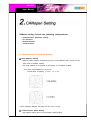
CANopen setting include the following configurations:
-
Communication parameter setting
I/O allocation
Default Identifier
Communication
1) Communication Parameter Setting
◆ Node Address Setting
- NA-9161 Node address is determined by the node address rotary switch on the
front panel of adapter module.
- Set node address is recognized on the power-on of adapter module.
Ex) When node address is set as 27:
Device MAC ID Setting :( 2*10 + 1*7 )= 27
* Each CANopen Adaptor has MAC ID No. from 0 to 99.
◆ Communication Speed Setting
- See Master Setting about communication speed setting.
Copyright(C) * CREVIS Co.,Ltd * Support +82-31-273-6452 * URL : www.crevis.co.kr
-5-
NA-9161
User Manual
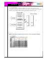
2) I/0 Allocation
The expansion Module connecting to Adaptor has 3 types of Data types (I/O Data,
Configuration Parameters, Memory Resister) These data are exchanging I/O Process image
Data via FnBus Protocol between Adaptor and Expansion Module as below ;
◆ Input Image Data is determined by the position of Slot and Expansion Module.
= For Example
Copyright(C) * CREVIS Co.,Ltd * Support +82-31-273-6452 * URL : www.crevis.co.kr
-6-
NA-9161
User Manual
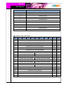
Slot Address
Module Description
0
CANopen Adaptor
1
4-Discrete input
2
8-Discrete input
3
2-Analog input
4
16-Discrete input
5
4-Discrete input
6
8-Discrete input
7
4-Discrete input
8
2-Analog input
9
16-Discrete input
10
1Ch , high speed counter
◆ Compress mode data format
Byte
Bit 7
Bit 6
Bit 5
Bit 4
Bit 3
Bit 2
Bit 1
Bit 0
Index
Sub-In.
0
Analog Input Ch0 low byte (Slot#3)
0x6401
0x01
1
Analog Input Ch0 High byte (Slot#3)
0x6401
0x01
2
Analog Input Ch1 low byte (Slot#3)
0x6401
0x02
3
Analog Input Ch1 High byte (Slot#3)
0x6401
0x02
4
Analog Input Ch0 low byte (Slot#8)
0x6401
0x03
5
Analog Input Ch0 High byte (Slot#8)
0x6401
0x03
6
Analog Input Ch1 low byte (Slot#8)
0x6401
0x04
7
Analog Input Ch1 High byte (Slot#8)
0x6401
0x04
8
Discrete Input 4pts (Slot#2)
Discrete Input 4pts (Slot#1)
0x6000
0x01
9
Discrete Input 4pts (Slot#4)
Discrete Input 4pts (Slot#2)
0x6000
0x02
0x6000
0x03
0x6000
0x04
0x6000
0x05
0x6000
0x06
0x6000
0x07
0x6000
0x08
10
11
12
13
14
15
Discrete Input 8pts (Slot#4)
Discrete Input 4pts (Slot#5)
Discrete Input 4pts (Slot#4)
Discrete Input 8pts (Slot#6)
Discrete Input 4pts (Slot#9)
Discrete Input 4pts (Slot#7)
Discrete Input 8pts (Slot#9)
Discrete Input 4pts (Slot#9)
16
HSC Input 0 byte (Slot#10)
0x3000
0x01
17
HSC Input 1 byte (Slot#10)
0x3000
0x02
18
HSC Input 2 byte (Slot#10)
0x3000
0x03
19
HSC Input 3 byte (Slot#10)
0x3000
0x04
20
HSC Input 4 byte (Slot#10)
0x3000
0x05
21
HSC Input 5 byte (Slot#10)
0x3000
0x06
Copyright(C) * CREVIS Co.,Ltd * Support +82-31-273-6452 * URL : www.crevis.co.kr
-7-
NA-9161
User Manual
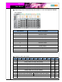
◆ Non-compress mode data format
Byte
Bit 7
Bit 6
Bit 5
Bit 4
Bit 3
Bit 2
Bit 1
Bit 0
Index
Sub-In.
0
Analog Input Ch0 low byte (Slot#3)
0x6401
0x01
1
Analog Input Ch0 High byte (Slot#3)
0x6401
0x01
2
Analog Input Ch1 low byte (Slot#3)
0x6401
0x02
3
Analog Input Ch1 High byte (Slot#3)
0x6401
0x02
4
Analog Input Ch0 low byte (Slot#8)
0x6401
0x03
5
Analog Input Ch0 High byte (Slot#8)
0x6401
0x03
6
Analog Input Ch1 low byte (Slot#8)
0x6401
0x04
7
Analog Input Ch1 High byte (Slot#8)
0x6401
0x04
0x6000
0x01
8
Reserved
Discrete Input 4pts (Slot#1)
9
Discrete Input 8pts (Slot#2)
0x6000
0x02
10
Discrete Input low 8pts (Slot#4)
0x6000
0x03
11
Discrete Input High 8pts (Slot#4)
0x6000
0x04
0x6000
0x05
0x6000
0x06
0x6000
0x07
12
13
14
Reserved
Discrete Input 4pts (Slot#5)
Discrete Input 8pts(Slot#6)
Reserved
Discrete Input 4pts (Slot#7)
15
Discrete Input low 8pts (Slot#9)
0x6000
0x08
16
Discrete Input High 8pts (Slot#9)
0x6000
0x09
0x6000
0x0A
17
Reserved
Discrete Input 4pts (Slot#10)
18
HSC Input 0 byte (Slot#10)
0x3000
0x01
19
HSC Input 1 byte (Slot#10)
0x3000
0x02
20
HSC Input 2 byte (Slot#10)
0x3000
0x03
21
HSC Input 3 byte (Slot#10)
0x3000
0x04
22
HSC Input 4 byte (Slot#10)
0x3000
0x05
23
HSC Input 5 byte (Slot#10)
0x3000
0x06
Copyright(C) * CREVIS Co.,Ltd * Support +82-31-273-6452 * URL : www.crevis.co.kr
-8-
NA-9161
User Manual
◆ Output Image Data is determined by the position of Slot and Expansion Module.
= For Example
Slot Address
Module Description
0
CANopen Adaptor
1
4-Discrete Output
2
8-Discrete Output
3
2-Analog Output
4
16-Discrete Output
5
4-Discrete Output
6
8-Discrete Output
7
2-Relay Output
8
2-Relay Output
9
2-Analog Output
10
16-Discrete Output
11
1Ch, High speed counter
◆ Compress mode data format
Byte
Bit 7
Bit 6
Bit 5
Bit 4
Bit 3
Bit 2
Bit 1
Bit 0
Index
Sub-In.
0
Analog Output Ch0 low byte (Slot#3)
0x6411
0x01
1
Analog Output Ch0 High byte (Slot#3)
0x6411
0x01
2
Analog Output Ch1 low byte (Slot#3)
0x6411
0x02
3
Analog Output Ch1 High byte (Slot#3)
0x6411
0x02
4
Analog Output Ch0 low byte (Slot#9)
0x6411
0x03
5
Analog Output Ch0 High byte (Slot#9)
0x6411
0x03
6
Analog Output Ch1 low byte (Slot#9)
0x6411
0x04
7
Analog Output Ch1 High byte (Slot#9)
0x6411
0x04
8
Discrete Output 4pts (Slot#2)
Discrete Output 4pts (Slot#1)
0x6200
0x01
9
Discrete Output 4pts (Slot#4)
Discrete Output 4pts (Slot#2)
0x6200
0x02
0x6200
0x03
10
Discrete Output low 8pts (Slot#4)
Copyright(C) * CREVIS Co.,Ltd * Support +82-31-273-6452 * URL : www.crevis.co.kr
-9-
NA-9161
User Manual
11
Discrete Output 4pts (Slot#5)
12
13
Discrete Output 4pts (Slot#4)
Discrete Output 8pts (Slot#6)
Discrete Output 4pts (Slot#10)
14
Discrete Output Discrete Output
2pts (Slot#8)
2pts (Slot#7)
Discrete Output High 8pts (Slot#10)
15
Reserved
Discrete Output 4pts (Slot#10)
0x6200
0x04
0x6200
0x05
0x6200
0x06
0x6200
0x07
0x6200
0x08
16
HSC Output low byte (Slot#10)
0x3200
0x01
17
HSC Output High byte (Slot#10)
0x3200
0x02
Index
Sub-In.
◆ Non-compress mode data format
Byte
Bit 7
Bit 6
Bit 5
Bit 4
Bit 3
Bit 2
Bit 1
Bit 0
0
Analog Output Ch0 low byte (Slot#3)
0x6411
0x01
1
Analog Output Ch0 High byte (Slot#3)
0x6411
0x01
2
Analog Output Ch1 low byte (Slot#3)
0x6411
0x02
3
Analog Output Ch1 High byte (Slot#3)
0x6411
0x02
4
Analog Output Ch0 low byte (Slot#9)
0x6411
0x03
5
Analog Output Ch0 High byte (Slot#9)
0x6411
0x03
6
Analog Output Ch1 low byte (Slot#9)
0x6411
0x04
7
Analog Output Ch1 High byte (Slot#9)
0x6411
0x04
0x6200
0x01
8
Reserved
Discrete Output 4pts (Slot#1)
9
Discrete Output 8pts (Slot#2)
0x6200
0x02
10
Discrete Output low 8pts (Slot#4)
0x6200
0x03
11
Discrete Output High 8pts (Slot#4)
0x6200
0x04
0x6200
0x05
0x6200
0x06
0x6200
0x07
0x6200
0x08
12
13
Reserved
Discrete Output 4pts (Slot#5)
Discrete Output 8pts (Slot#6)
14
Reserved
15
Reserved
Discrete Output
2pts (Slot#7)
Discrete Output
2pts (Slot#8)
16
Discrete Output low 8pts (Slot#10)
0x6200
0x09
17
Discrete Output High 8pts (Slot#10)
0x6200
0x0A
0x6200
0x0B
18
Reserved
Discrete Output 4pts (Slot#11)
19
HSC Output low byte (Slot#11)
0x3200
0x01
20
HSC Output High byte (Slot#11)
0x3200
0x02
Copyright(C) * CREVIS Co.,Ltd * Support +82-31-273-6452 * URL : www.crevis.co.kr
- 10 -
NA-9161
User Manual
3) CANopen I/O Data Format Setting
I/O Data format of NA-9161 is able to be changed to CANopen Configuration
Software Setting Data format by changing object value of Configuration software.
◆ FnBus Communication register Format
- The index 0x4500 are can be access via SDO.
FnBus Error monitor data format : This object are FnBus state.
Index
0x4500
Sub-Index
Decimal Byte
Data Type
Description
Byte 00
unsigned8
FnBus Error Code
Byte 01
unsigned32
Error Slot number
Byte 02
unsigned8
Reserve
Byte 03
unsigned32
Field Power state
0x80: not supply, 0x00: supply
0x01
Ex) Data Read : Id=RxSDO DLC=8; Data=40 00 45 01 xx xx xx xx
FnBus Data mode : The process image are can be changed via this object.
Index
Sub-Index
Decimal Byte
Data Type
Description
0 : non-compress mode
0x4500
0x02
Byte 00
unsigned8
1 : compress mode
Ex) Data Read : Id=RxSDO DLC=8; Data=40 00 45 02 xx xx xx xx
Data Write : Id=RxSDO DLC=8; Data=2F 00 45 02 01 xx xx xx(compress mode set)
Expansion module active flag data format : The IO slot are deactivated via the bit flag.
Index
0x4500
Sub-Index
0x03
Data Type
Data Type
Description
Bit 00
Active/Deactiveate flag for slot
position #1 (0:Active, 1:Deactivate)
Bit 01
Active/Deactiveate flag for slot
position #2 (0:Active, 1:Deactivate)
Bit 02
Active/Deactiveate flag for slot
position #3 (0:Active, 1:Deactivate)
:
:
Bit 30
Active/Deactiveate flag for slot
position #31 (0:Active, 1:Deactivate)
Bit 31
Active/Deactiveate flag for slot
position #32 (0:Active, 1:Deactivate)
unsigned32
Copyright(C) * CREVIS Co.,Ltd * Support +82-31-273-6452 * URL : www.crevis.co.kr
- 11 -
NA-9161
User Manual
◆ Digital Data Bit size Information
- The index is can be access via SDO.
Input bit size information : All digital input data are counted
Index
Sub-Index
Decimal Byte
Data Type
Description
0x2020
0x01
Byte 00
unsigned8
All Digital input bit size
Ex) Data Read : Id=RxSDO DLC=8; Data=40 20 20 00 xx xx xx xx
Output bit size information : All digital output data are counted
Index
Sub-Index
Decimal Byte
Data Type
Description
0x2220
0x01
Byte 00
unsigned8
All Digital output bit size
Ex) Data Read : Id=RxSDO DLC=8; Data=40 20 22 00 xx xx xx xx
◆ Special IO Data Block
Special Input Block
Index
Sub-Index
Decimal Byte
Data Type
Description
0x01
Byte 00
unsigned8
0h~7h Special input data
0x02
Byte 01
unsigned8
8h~15h Special input data
:
:
:
:
0x64
Byte 64
unsigned8
1F8h~1FFh Special input data
0x3000
Special Output Block
Index
Sub-Index
Decimal Byte
Data Type
Description
0x01
Byte 00
unsigned8
0h~7h Special output data
0x02
Byte 01
unsigned8
8h~15h Special output data
:
:
:
:
0x64
Byte 64
unsigned8
1F8h~1FFh Special output data
0x3200
Copyright(C) * CREVIS Co.,Ltd * Support +82-31-273-6452 * URL : www.crevis.co.kr
- 12 -
NA-9161
User Manual
4) Default Identifier
CANopen provides default identifiers for the most important communication objects, and
these are derived from the 7-bit node address(the node ID) and a 4-bit function code in
accordance with the following scheme:
11Bit Identifier
10
9
8
7
6
5
Function
4
3
2
1
0
Code Node ID
The COB ID are given according to DS301. This gives rise to the following default
identifiers:
Object
Function
Function
Code
Object for
Communication
COB ID(hex/dec)
parameter/mapping
NMT
Boot-up
0000
0x00/0
-
SYNC
Synch.
0001
0x80/128
0x1500+0x1006
EMERGENCY Status/Error
0001
0x81-0xFF/129-255
-
PDO 1(Tx)
Digital Input
0011
0x181-0x1FF/385-511
0x1800/0x1A00
PDO 1(Rx)
Digital Output
0100
0x201-0x27F/513-639
0x1400/0x1600
PDO 2(Tx)
Analog Input
0101
0x281-0x2FF/641-767
0x1801/0x1A01
PDO 2(Rx)
Analog Output
0110
0x301-0x37f/769-895
0x1401/0x1601
SDO (Tx)
Parameter
1011
0x581-0x5ff/1409-1535
-
SDO (Rx)
Parameter
1100
0x601-0x67F/1537-1663
-
Nodeguard
Life/Nodeguard 1110
0x701-0x77F/1793-1919
0x100C,0x100D,0x100E
The COB ID can be changed vis SDO.
The PDOs 3-8 do not have default values in DeviceProfile 402. The COD ID of these
PDOs have to be set by the user with regard to the COB ID which are already use by
the network.
5) COMMUNICATION
- Structure of the device model
Communication. This function unit makes the communication data objects and the
associated functionality for data exchange over the CANopen network available.
The network status machine is part of this.
Object directory. This contains all the data objects (application data + parameters)
that are accessible from outside and that affect the behavior of communication,
application and status machines. The object directory is organized as a two-dimensional
table in which the data are addressed by their index and sub-index.
The data exchange with CANopen devices takes place by means of data objects. In the
CANopen communication profile, two types of standard object (PDO and SDO) and special
Copyright(C) * CREVIS Co.,Ltd * Support +82-31-273-6452 * URL : www.crevis.co.kr
- 13 -
NA-9161
User Manual
objects (for network management etc.) are defined.
The NA-9161 support the following objects:
.
.
.
.
.
.
.
8 transmit PDOs
8 receive PDOs
1 standard SDO (server)
1 emergency object
1 synchronization object ( SYNC, without time stamp )
node guarding
NMT objects
Every CANopen device possesses a CANopen object directory in which the
parameters for all the CANopen objections are entered.
- PDO (Process Data)
In many fieldbus systems the entire process image is continuously transferred - usually
in a more or less cyclic manner.
CANopen is not limited to this communication principle, since the multi-master bus access
protocol allow CAN to offer other methods.
The process data in CANopen is divided into segments with a maximum of 8 bytes.
These segments are known as process data objects(PDOs). The PDOs each correspond
to a CAN telegram, whose specific CAN identifier is used to allocate them and to
determine their their priority.
The PDOs are named from the point of view of the bus coupler: receive PDOs (RxPDOs)
are received by the coupler and contain output data, while transmit PDOs (TxPDOs)
are sent by the coupler and contain input data.
- PDO Mapping
CANopen specifies the data assignment for the first two PDOs in the device profile for
input/output groups(DS401)("default mapping"). The first PDO is provided for digital inputs
(TxPDO1) or outputs (RxPDO1). The first 4 analog inputs or outputs are located in
second PDO. These PDOs are accordingly occupied by the bus couplers - if , for instance,
no digital output terminals are plugged in RxPDO1 remains empty.
Once the first PDOs have been occupied, the next PDOs are filled with process data in
the following sequence :
1. Digital I/Os (1-byte)
2. Digital I/Os (2-byte)
3. Analog I/Os
Copyright(C) * CREVIS Co.,Ltd * Support +82-31-273-6452 * URL : www.crevis.co.kr
- 14 -
NA-9161
User Manual
- PDO Identifier
For the first two PDOs(PDO1 + PDO2) CANopen provides default identifiers depending on
the node address, but all other PDOs must have identifiers assigned to them.
The principle of the default identifiers is explained in the section on "Network
Manangement" and there is a list of all the CANopen default identifiers in the appendix.
Pre-Define Connection Set
In the system of default identifiers all the nodes (here : salves) communicate with one
central station (the master), since slave nodes do not listen by default to the send
identifier of other slave nodes:
PDO Linking
If the consumer-producer model of CANopen PDOs is to be used for direct data
exchange between nodes (without a master), the distribution of identifiers must be
appropriately adapted, so that the TxPDO identifier of the producer agrees with the
RxPDO identifier of the consumer:
Copyright(C) * CREVIS Co.,Ltd * Support +82-31-273-6452 * URL : www.crevis.co.kr
- 15 -
NA-9161
User Manual
This procedure is known as PDO linking. It permits, for example, easy construction of
electronics drives in which several slave axes simultaneously listen to the actual value
in the master axis TxPDO.
- PDO Communication Type (Event driven)
The "event" is the alteration of an input value, the data being transmitted immediately after
this change. The event-driven flow can make optimal use of the bus bandwidth, since
instead of the whole process image it is only the changes in that are transmitted. A short
reaction time is achieved at the same time, since when an input value changes it is not
necessary to wait for the next interrogation from a master.
Polling
The PDOS can also be polled by data request telegrams (remote frames). In this way
it is possible to get the input process image of event-driven inputs onto the bus, even
when the inputs have not changed, for instance by a monitoring or diagnostic device
brought into the network while it is running.
The Crevis CANopen bus adaptor support the interrogation of PDOs by means of remote
frames.
Synchronized
It is not only for drive applications that it is worthwhile to synchronize the determination
of the input information and the setting the outputs. For this purpose CANopen provides
the SYNC object, a CAN telegram of high priority but containing no user data, whose
reception is used by the synchronized nodes as a trigger for reading the inputs or for
setting the outputs:
PDO transmission type
The "PDO transmission type" parameter specifies how the transmission of the PDO is
triggered, or how received PDOs handled:
Transmission
type
PDO transmission
cyclic
0
1-240
acyclic
X
X
synchronous asynchronous
RTR only
X
X
241-251
Reserved
252
X
X
253
X
254
X
255
X
Copyright(C) * CREVIS Co.,Ltd * Support +82-31-273-6452 * URL : www.crevis.co.kr
X
- 16 -
NA-9161
User Manual
Synchronous
Transmission type 0 is only useful for RxPDOs: the PDO is only used when the next
SYNC telegram is received. In transmission type 1-240 the PDO is cyclically transmitted
or expected : after every "nth" SYNC (n=1...240).
since transmission types can be combined on a coupler as well as in the network, it is
possible, for example, for a fast cycle to be agreed for digital inputs (n=1), whereas the
data for analogue inputs is transmitted in a shower cycle (e.g.n=10).
The cycle time (SYNC rate) can be monitored (object 0x1006), so that if the SYNC fails
the Adaptor switches its outputs into the fault state.
Asynchronous
The transmission types 254 + 255 are asynchronous, but may also be event-driven.
In transmission type 254, the event is specific to the manufacturer, whereas for type 255
it is defined in the device profile.
Inhibit Time
The "inhibit time" parameter can be used to implement a " transmit filter" that dose not
increase the reaction time for relatively new input alterations, but is active for changes that
follow immediately afterwards. The inhibit time (transmit delay time) specifies the minimum
length of time that must be allowed to elapse between the transmission of two the same
telegrams. If the inhibit time is used, the maximum bus loading can be determined, so that
the worst case latency can then be found.
SDO(Service Data)
The parameters listed in the object directory are read and written by means of service data
objects. these SDOs are Multiplexed domains, i.e. structures of any size that have a
multiplexor (address). The multiplexor consist of a 16-bit index and an 8-bit sub-index that
that address the corresponding entries in the object directory.
Byte0
Byte1-3: data addressing
Command
Index
Specifier
Low Byte High Byte
-
Index
Byte4-7: 1-4byte of data
Subindex
Data0
Data1
Data 2
Data 3
Upload
Download
Number of data byte
Request
Response
Copyright(C) * CREVIS Co.,Ltd * Support +82-31-273-6452 * URL : www.crevis.co.kr
- 17 -
NA-9161
User Manual
Index
Sub-index
Data
The CANopen bus couplers are servers for the SDO, which means that at the request
of a client they make data available (upload), or they receive data from the client (downlad).
This involves a handshake between the client and the server. When the size of the
parameter to be transferred is not more than 4 bytes, a single handshake is sufficient
(one telegram pair).
For a download, the client sends the data together with its index and subindex and
the server confirms reception. For an upload, the client requests the data by transmitting
the index and sub-index of the desired parameter, and the server sends the parameter
(including index and sub-index) in its answer telegram. The same pair of identifiers is
used for both upload and download. The telegrams, which are always 8 bytes long,
encode the various services in the first data byte.
All parameters with the exception of objects 1008h, 1009h and 100Ah(device name,
hardware and software versions) are only at most 4 bytes long, so this description
is restricted to transmission in expedited transfer.
Copyright(C) * CREVIS Co.,Ltd * Support +82-31-273-6452 * URL : www.crevis.co.kr
- 18 -
NA-9161
User Manual
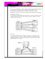
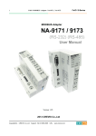
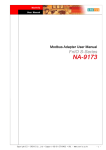
CANOpen Network Set up is like following figure1.
Figure 1. CANOpen Network Example
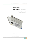
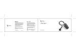
1) CANopen Network Start-up
CANopen defines a state machine that controls the functionality of a device. Transition
between the individual states is initiated by internal events or services from the NMT
master. These devices states can be connected to application processes.
Figure 2. State diagram of
a Simple CANopen Boot Up
Copyright(C) * CREVIS Co.,Ltd * Support +82-31-273-6452 * URL : www.crevis.co.kr
- 19 -
NA-9161
User Manual
In Initialization state, the CANopen data structures of a node are initialized by the
application. The CIA DS-301 standard defines various mandatory OD entries for this task
as well as specific communication objects required for that. In the minimum device
configuration, the identifier for these communication objects must correspond to the
so-called pre-Defined
Connection-Set. The device profiles define further settings for the applicable device class.
The pre-defined settings for identifier for emergency, PDOs and SDOs are calculated based
on the node address(Node ID), that can be in the range from 1 to 99, added to a base
identifier that determines the function of the individual object.
After Initialization is completed the node automatically switches into PRE-OPERATIONAL(12)
states. The NMT master will be informed about this state change with the BOOT-UP
message sent by the corresponding node. In this state it is not possible to communicate
with the node using PDOs. However, the node can be configured over the CAN bus using
SDOs PRE-OPERATIONAL state. NMT services and Life Guarding are also available in
this state.
The application as well as the available resources of the CANopen device determine to
what extend configuration over the CAN bus with the help of SDOs must take place.
For example, if the CANopen device dose not provide a non-volatile memory to store
mapping and communication parameters for PDOs and these parameters differ from the
default values, then these parameters must be transmitted to the node over the network
after initialization is completed.
After the configuration of these parameters by the application or NMT master is completed,
the NMT service start_Remote_Node(6) can be use to render the node from
PRE-OPERATIONAL state into OPERATIONAL state. This state change also causes the
initial transmission of all TPDO s independently of whether an event for it is present.
Each subsequent transmission of PDOs then always takes place as a function of an event.
All CANopen devices also support the Stop_Remote_Node(7), Enter_PRE_OPERATIONAL_
State(8), Reset_Node(10), Reset_Communication(11)services.
Reset_Node is used to reset the application-specific data and the communication parameter
of the node. This state change is comparable with an initial operation of the node.
If the NMT service Reset_Communication is used to Change the state of a node, then
loading initial values exclusive for the communication parameters in the CANopen stack
takes place.
No communication via PDO and SDO is possible if the device is in STOPPED state. Only
NMT services, Node Guarding, Life Guarding as well as Heartbeat are possible in this state
2) Boot-up Message
After the initialization phase and the self test, the bus coupler sends the boot-up message,
a CAN message with no data bytes and with the identifier of the emergency message :
CAN-ID = 0x80 + node ID.
Copyright(C) * CREVIS Co.,Ltd * Support +82-31-273-6452 * URL : www.crevis.co.kr
- 20 -
NA-9161
User Manual
3) Node Guarding
Node Guarding represents a means of node supervision that is initiated by the NMT master.
This service is used to request the node's operational state and to determine whether the
node is functioning correctly. The NMT master transmits a single
Node Guard message to the slave in the form of a remote frame with the CAN identifier
0x700 plus the node address of the NMT slave. As a response to this remote frame, the
NMT slave sends a CAN message back containing its current NMT state and a one bit
that toggles between two subsequent messages.
Response from the NMT Slave to a Node Guard Remote Frame:
Identifier
DLC
0x700 + Node Address
1
Data
0
Status Byte
Node State of a CANopen Device
Status Byte
Node State
0x00
BOOT-UP
0x04
STOPPED
0x05
OPERATIONAL
0x7F
PRE-OPERATIONAL
Bit 7 of the status byte always starts with a 0 and changes its value after each
transmission. The application is responsible for actively toggling this bit. This ensures that
the Node Guard response message from a slave is not just stored in one of the Full-CAN
channels. Thus the NMT master will get the confirmation from the NMT slave node that
the application is still running.
4) Life Guarding
As an alternative to Node Guarding node supervision can also be performed by Life
Guarding services. In contrast to the Node Guarding the NMT master cyclically sends a
Life Guard message to the slave in the form of a remote frame with the CAN identifier
0x700 plus the node address of the NMT slave. As a response to this remote frame, the
NMT slave sends a CAN message back containing its current NMT state and a one bit
that toggles between two subsequent messages. With being missing the answer or
unexpected status of the slave the NMT masters application is informed. Further the slave
can detect the loss of the masters. The Life Guarding is started with the transmission of
the first Life Guard message of the masters.
Response from the NMT Slave to a Life Guard Remote Frame
Copyright(C) * CREVIS Co.,Ltd * Support +82-31-273-6452 * URL : www.crevis.co.kr
- 21 -
NA-9161
User Manual
Identifier
DLC
0x700 + Node Address
1
Data
0
Status Byte
Meaning of the status byte corresponds to that of he Node Guarding message. The Life
Guarding supervision on the NMT slave node is deactivated, if the Life Guard time (object
entry 0x100C in the object dictionary) or the Life time factor(object entry 0x100D in the
object dictionary) are equal to zero.
Copyright(C) * CREVIS Co.,Ltd * Support +82-31-273-6452 * URL : www.crevis.co.kr
- 22 -
NA-9161
User Manual
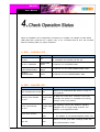
When all installation and configuration processes are complete, the adaptor module status
LED( RUN LED ) shall be lit in a green color. If not, it indicates that an error has occurred.
See the following table for proper measures.
1) RUN : CAN-RUN LED
State
LED is
Description
Not Powered Not
On-line
Off
The Device is not on-line or may be not powered
Not completed the Dup-Mac_ID test yet
On-line, STOPPED
Single Flash
Green
The Device is in STOPPED state
On-line,
PRE-OPERATIONAL
Blinking
On-line,
OPERATIONAL
Green
Green
The Device is in the PRE-OPERATIONAL state
The Device is in the OPERATIONAL state
2) ERR : CAN-ERR LED
State
LED is
Not Powered Not On-line Off
Description
Device is in mode baud rate search or may be
not powered.
At least one of the error counters of the CAN
Warning limit reached
Single Flash
On-line
Red
Error Control Event
On-line
The guarding monitor has asserted, guarding
Double Flash
telegrams are no longer being received. The
Red
adapter is pre-operational state.
Sync Error On-line
Bus Off
Triple Flash
Red
Red
controller has reached or exceeded the warning
level(too many error frames).
A sync error has occurred.
- The adapter is pre-operational(PDOs switch off).
Device is in the cyclic data exchange mode with
the parameterization master
Copyright(C) * CREVIS Co.,Ltd * Support +82-31-273-6452 * URL : www.crevis.co.kr
- 23 -
NA-9161
User Manual
3) I/O : Expansion Module Status LED
State
Not Powered
No Expansion Module
FnBus On-line,
Do Not Exchanging I/O
FnBus Connection
Run Exchanging I/O
FnBus connection fault
during exchange IO
LED is
To Indicate
Device has no expansion module or may not be
Off
powered
Fn-Bus is on-line but does not exchanging I/O data
Flash
Green
- Passed the expansion module configuration.
Expansion Slot is connected and run exchanging I/O
Green
data
One or more expansion module occurred in fault state
Red
- FnBus communication failure
Failed to initialize expansion module
- Detected invalid expansion module ID
Expansion Configuration Flash
Red
Failed
- Overflowed Input/Output Size
- Initial protocol failure
4) Field Power : Field Power Status LED
State
LED is
To Indicate
Not Supplied Field Power
Off
Not supplied 24Vdc field power
Supplied Field Power
Green
Supplied 24Vdc field power
Copyright(C) * CREVIS Co.,Ltd * Support +82-31-273-6452 * URL : www.crevis.co.kr
- 24 -