1
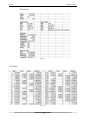
NHT-3D
Complex Signal Analyzer
User Manual
II
!
!
!
!
!
!
!
!
!
!
!
!
!
!
!
!
!
!
!
!
!
!
!
!
!
!
!
!
!
!
!
!
!
!
!
!
!
!
!
!
!
!
!
!
!
!
!
!
!
Progettazione sviluppo e produzione
MICRORAD
P.zza delle Azalee 13/14
05019 Orvieto (TR) – ITALIA
Tel +39 0763393291
Fax +39 0763394423
email [email protected]
web www.microrad.it
Release 2.3 March 2014
III
INDEX
1" GENERAL"INFORMATIONS"..................................................................................................................."1"
1.1"APPLICATIONS"........................................................................................................................................."1"
1.2"ABOUT"THE"INSTRUMENT"..................................................................................................................."1"
1.3"OPERATING"MODES"................................................................................................................................"1"
1.3.1! Single*EMF*measurements*............................................................................................................................*1!
1.3.2! NHT*3D*remote*control*using*Waves*software*....................................................................................*2!
1.3.3! Downloading*data*from*NHT*3D*to*PC*using*Waves*software*.....................................................*2!
1.4"MEASUREMENT"PROBES"......................................................................................................................"2"
1.5"GPS"MODULE"AND"TEMPERATURE"SENSOR"..................................................................................."3"
1.6"ITEMS"INCLUDED"(BASE"CONFIGURATION)"..................................................................................."3"
1.7"TECHNICAL"SPECIFICATIONS".............................................................................................................."4"
1.7.1! NHT*3D*unit*specifications*............................................................................................................................*4!
1.8"STANDARDS"COMPLIANCE"..................................................................................................................."5"
2" SAFETY"SUMMARY".................................................................................................................................."6"
2.1"FOREWORD"..............................................................................................................................................."6"
2.2"CORRECT"USE"..........................................................................................................................................."6"
3" CERTIFICATION"AND"WARRANTY"....................................................................................................."7"
3.1"WARRANTY"..............................................................................................................................................."7"
3.2"LIMITATION"OF"WARRANTY"..............................................................................................................."7"
4" LEGEND"OF"BASIC"UNIT"........................................................................................................................"8"
4.1"KEYBOARD"LEGEND"..............................................................................................................................."8"
4.2"LEGEND"OF"CONNECTORS"AND"INTERFACES"..............................................................................."10"
5" PREPARATION"FOR"USE"......................................................................................................................"12"
5.1"UNPACKING"............................................................................................................................................."12"
5.2"STORAGE".................................................................................................................................................."12"
5.3"CONNECTING"THE"PROBE".................................................................................................................."13"
5.4"POWER"SUPPLY"....................................................................................................................................."13"
5.4.1! Operating*time*..................................................................................................................................................*14!
6" OPERATION"............................................................................................................................................."15"
6.1"SWITCHING"ON"......................................................................................................................................"15"
6.2"MAIN"MEASURING"SCREEN"................................................................................................................"17"
6.3"RECORDING"MEASURED"VALUES"....................................................................................................."18"
6.3.1! Single*value*storing*........................................................................................................................................*19!
6.4"DATA"TRANSFER"AND"DISPLAY"......................................................................................................."19"
6.5"SPATIAL"MODE"......................................................................................................................................"19"
6.6"ALERT"LEVEL".........................................................................................................................................."19"
6.7"FACTORY"RESET"...................................................................................................................................."20"
IV
7" WAVES"SOFTWARE"..............................................................................................................................."21"
7.1"DESCRIPTION"........................................................................................................................................."21"
7.2"SOFTWARE"INSTALLATION"..............................................................................................................."21"
7.3"COMMANDS"E"FUNCTIONS"................................................................................................................."22"
7.4"CONFIGURATION"COMMANDS".........................................................................................................."25"
7.5"MEASUREMENTS"FUNCTIONS"..........................................................................................................."27"
7.6"NHT"3D"PARAMETER"CONFIGURATION"AND"SETTINGS".........................................................."28"
7.7"DOWNLOADING"DATA"FROM"THE"NHT"3D"(DOWNLOAD)"....................................................."28"
7.7.1! “Snapshots”*section*.........................................................................................................................................*28!
7.7.2! Section**Markers*–*Zoom*and**Pan*...........................................................................................................*30!
7.8"EXPORTING"DATA"IN"TABULAR"FORMAT"(EXPORT"DATA)"..................................................."31"
7.9"GPS"AND"GOOGLE"MAPS"......................................................................................................................"33"
7.10UPDATING"THE""NHT"3D"FIRMWARE"(FW"UPDATE)"..............................................................."34"
V
1
GENERAL INFORMATIONS
1.1 Applications
The human exposure to electromagnetic fields (not ionizing radiation) is
nowadays a very critical subject almost all countries in the world are dealing
with. Technical and normative bodies worked alongside government
institutions to enact new guidelines and decrees about maximum permitted
exposure levels for populations and workers.
The measurement equipment for this kind of analysis must suit the technical
requirements from the guidelines and must provide the user with qualified
physical parameters for comparing with law thresholds.
1.2 About the instrument
NHT 3D is the new Microrad solution for the measurement and analysis of
complex signals in the electromagnetic safety applications.
Besides being handy and compact, the instrument operates in Selective mode
in the frequency band DC÷400 kHz.
It is user-friendly and very reliable in the measurements; it is also able to
provide the environment temperature and GPS coordinates of measuring site
to draw up a final report at the best.
1.3 Operating modes
1.3.1 Single EMF measurements
Main application of NHT 3D is to execute single selective or wideband EMF
measurements. The system can manage several probes in order to take a
measure of the physical parameter (magnetic induction, magnetic field and
electric field) and frequency band needed.
In a single screen (on LCD display) are always displayed:
! Instantaneous isotropic value (ISO) of measured field level.
! Battery charging level.
! Frequency Span.
! Occupational or Population environment.
! Measurement unit.
! GPS on/off.
! Temperature.
! Date and time clock.
The instrument can be used in a standard mode directly operating through its
frontal keyboard. The acquisition of single measurement values is always
done by user command [STORE (SINGLE)]. Every single value is stored in a
specific memory partition reserved for single measurements (total 1024
values) in conjunction with general information about date and time clock,
GPS coordinates and temperature.
NHT 3D
1. Informazioni generli
1.3.2
NHT 3D remote control using Waves software
This operation mode is suggested to avoid as much as possible the user
presence influencing the measurement environment (mainly for electric fields
analysis); or if it is requested to install the measuring system in a screened
and controlled space (anechoic chamber for EMC testing). In such situation is
strongly suggested a wooden tripod with variable height (optional).
NHT 3D can be managed in remoting mode through a fiber optic connection
(transparent not conductive material) to an external PC. Waves allows the total
remote control of the NHT 3D unit displaying the measured values, the
indexes and the masks relating to occupational or population regulations.
Simultaneously it displays the graphic curves Amplitude vs Time and
Amplitude vs Frequency, upper and lower windows on the screen respectively.
1.3.3
Downloading data from NHT 3D to PC using Waves software
All measured values, recorded both as single store must be downloaded to an
external PC through the fiber cable and Waves software to be viewed and
analyzed.
Waves allows to configurate the data of the device, such as to set the
threshold for an alarm of high field, the frequency span, the date and time and
erase the memory of the individual measurements acquired (snapshots).
1.4 Measurement probes
Several measurement probes are available to be used in conjunction with NHT
3D, in the frequency range from DC to 400kHz the available probes are:
" 10B : for measurements of magnetic induction (B) frequency range
from 5Hz to 400kHz; dynamic range from 0,1µT to 1mT.
" 11E : for measurements of electric field (E) frequency range from 5Hz a
400kHz; range di acquisizione da 20V/m a 20kV/m (CW).
" 20B : for measurements of magnetic induction (B) frequency range
from 5Hz a 20kHz; range di acquisizione da 300nT a 16mT.
" 30B : for measurements of magnetic induction (B) frequency range
from 5Hz a 400kHz; range di acquisizione da 300nT a 16mT.
" 20H : for measurements of magnetic induction (B) frequency range
from 0Hz a 1000Hz; range di acquisizione da 1mT a 15T.
" 30H : for measurements of magnetic induction (B) frequency range
from 0Hz a 1000Hz; range di acquisizione da 200µT a 600mT.
Each probe is automatically recognized by the NHT 3D when inserted.
Please refer to our website for additional technical details of the Probes.
(www.microrad.it).
2
NHT 3D
1. Informazioni generli
1.5 GPS module and temperature sensor
NHT 3D integrates a GPS module to acquire geographic coordinates as
reference to performed measurements.
In case of outdoor activities it is always suggested to add the GPS data related
to the measurement site in order to mention them in the final report.
No other external device is required to perform these operations as the NHT
3D performs the measurement and automatically provides field values
together with GPS coordinates of the site. The Waves software can directly
show it on Google Maps™.
In addition NHT 3D integrates a temperature sensor acquiring the
temperature value during measurement execution. Since the sensor is
installed in the front section of the instrument it is suggested to accept the
related value only if the unit is installed on a tripod and not if in the operator’s
hand. The shell of the meter is made by magnesium and it could conduct the
hand heat and thus influence the showed temperature value.
1.6 Items included (Base Configuration)
The basic unit NHT 3D is delivered in the standard configuration including:
! NHT 3D basic unit for measuring, storing and display field data
! Fiber optic cable (10 meters lenght)
! Fiber-USB-adapter to link fiber optic to PC
! USB A/B adapter cable
! Battery charger
! Waves software and user manual available available on website in the
download area (www.microrad.it)
! ISO 9001:2008 calibration certifictes
In order to proper work the NHT 3D meter must be connected to a
measurement probe to be chosen among the available ones.
3
NHT 3D
1. Informazioni generli
1.7 Technical specifications
1.7.1
NHT 3D unit specifications
PROBE TYPES
Frequency range
DC to 400kHz with different E and B/H
DISPLAY
Type
Transflective LCD monochrome
Size
7 cm , 128x64 dots
Backlight
Electroluminescent sheet switchable 10s/continuous
MEASUREMENT FUNCTIONS
Result unit
V/m, Tesla
Dispaly range
da 0.0001 a 999999 (dipende dal probe e dalle unità selezionate)
Result types (isotropic, RSS)
Istantaneo (ACT), Massimo (MAX), Media (AVG), Mediana
Space Average
SPT
Indexes on dispaly fo the meter
WP10 e IB50
Indexes on sw Waves
WP10, II98, IB50, IRMS and IRSS
STORAGE MODE
Samples
65.536 (monitoring sequences) / 1024 (snapshots)
INTERFACES
Optical interface
Serial, full duplex
Probe interface
Plug-and-play auto detection, LEMO™ connector
GPS
Model
FALCOM FSA03 quadrifilar helix
Receiver
50 channels, tracking L1 C/A code, update rate 4Hz, NMEA
Time to first position (TTFF)
Cold start 29 sec, warm start 29 sec, hot start < 1 sec
Sensitivity
Tracking -160dBm, autonm. acquisition -144dBm
GENERAL SPECIFICATIONS
Recommended calibration interval
24 months
Battery
Operation time
Li-ion rechargeable batteries, 4 x AA
Approx. 3 hours (backlight off). Available as option battery for
longer operation time (Aprox. >24h)
Charging time
3 ore
Battery level display
Graphic bar
Temperature range
Operativa da -10 °C a +50 °C
Immagazzinaggio da -20 °C a +70°C
Humidity
da 5 a 95%, non-condensing
Size (h x w x d)
160 x 98 x 46 mm (without probe)
Weight
Approx. 600 g (including batteries without probe)
AC charger, fiber optic (10mt), USB-Optical Converter, User
manual, Waves software, Iso 9001:2008 calibration certificate
Accessories (included)
Note: technical specifications are subject to change without any prior notice.
Note: technical specifications are subject to change without any prior notice.
4
NHT 3D
1. Informazioni generli
1.8 Standards compliance
ESD e EMC
Electrical equipment for measurement, control and laboratory use. EMC
requirements: radiating emission, radiating immunity in radio frequency,
electrostatic discharge.
CEI EN 61326
SICUREZZA
Safety requirements for electrical equipment for measurement, control and
laboratory use – General requirements.
CEI EN 61010
Marchio CE
Europena Union
OK
Country of origin
ITALY
5
2
SAFETY SUMMARY
2.1 Foreword
The following general safety precautions must be observed during all phases
of operation, service, and repair of this instrument. Failure to comply with
these precautions or with specific WARNINGS elsewhere in this manual may
impair the protection provided by the equipment. Such noncompliance would
also violate safety standards of design, manufacture, and intended use of the
instrument.
2.2
Correct use
• Keep away from live circuits
Operators must not remove instrument covers. Component replacement and
internal adjustments must be made by qualified maintenance personnel. Do
not replace components with the power cable connected. Under certain
conditions, dangerous voltages may exist even with the power cable removed.
To avoid injuries, always disconnect power and discharge circuits before
touching them.
• DO NOT substitute parts or modify instrument
To avoid the danger of introducing additional hazards, do not install substitute
parts or perform unauthorized modifications to the instrument. Return the
instrument to Microrad Service Center for service and repair to ensure that
safety features are maintained in operational condition.
Certification and Warranty
NHT 3D
3
1. Informazioni generli
CERTIFICATION AND WARRANTY
Microrad certifies that this product met its published specifications at the time
of shipment from the factory..
3.1
Warranty
This Microrad product is warranted against defects in material and
workmanship for a period of 24 months. Accessories are warranted for a
period of 6 months. During the warranty period, Microrad will, at its option,
either repair or replace products that prove to be defective.
For warranty service or repair, this product must be returned to Microrad. User
shall prepay shipping charges to Microrad and manufacturer shall pay
shipping charges to return the product to User.
Microrad warrants that its software and firmware designated by Microrad for
use with an instrument will execute its programming instruction when property
installed on that instrument.
3.2
Limitation of Warranty
The foregoing warranty shall not apply to defects resulting from improper or
inadequate maintenance by User, User-supplied software or interfacing,
unauthorized modification or misuse, operation outside the environmental
specifications for the product, or improper site preparation or maintenance.
7
4
LEGEND OF BASIC UNIT
4.1 Keyboard legend
The following table refers to Figure 4.1 which shows the numeric and function
keys on the front panel of the base unit.
Some keys have a second function indicated in orange which can be
enabled by pushing the middle button in advance [SHIFT].
1
2
3
4
5
12
6
7
13
8
9
14
10
11
15
NHT 3D
4. Legenda dell’unità base
Fig. 4.1
Item
Device/Key
Function
1
GPS antenna
2
Probe connector
3
Battery charger input
4
Display and Backlight
5
Temperature sensor
MODE Key
SPAN: sequentially selects the frequency span (1 kHz, 20
kHz e 400 kHz)
SHIFT + (LEVEL): select the application environment by
Occupational (OCC) in Population (POP) and viceversa
6
STORE Key
7
SINGL: pressing this key for storing a single value of
measurement (snapshot)
SHIFT + [REC]: Not available.
LIGHT Key
8
TEMP: temporary back light of display
SHIFT + [CONT]: continuous back light of display
9
10
SHIFT key
Enables all orange defined functions
POWER Key
ON: switches the instrument on.
SHIFT + [OFF]: switches the instrument off.
GPS Key
11
ON: enables the GPS module.
SHIFT + [OFF]: disables the GPS module.
Blue LED of battery charging in progress
Led on (bright light): batteries charging
12
Led on (weak light) battery maintenance charge
(battery charging level> 90%
Led off: Battery charging is complete
9
NHT 3D
4. Legenda dell’unità base
RESET Key
13
MAX: reset of MAX value measured.
SHIFT+[SPT]: resets the value of the space average (SPT)
SELECT Key
INDEX: sequentially selects the indexes / axes (WP10,
IB50; axes: X, Y, Z)
SHIFT + [ALARM]: Enables and disables acoustic alarm of
exceeding exposure threshold
14
TOPT. Key
15
ON: future additional function / Options
SHIFT + [OFF]: future additional function / Options
Tab. 4.1 – Keyboard legend
4.2 Legend of connectors and interfaces
The tables below refer to the connectors and interfaces available on the back
and at the top of the base
unit.
1
Fig. 4.1
Item
Name
Function
1
OPTICAL/SERIAL
Fiber optic cable interface for connection to a
remote PC
10
NHT 3D
4. Legenda dell’unità base
Tab. 4.2 – Connectors/Interfaces on the rear part of NHT 3D
1
2
Fig. 4.3
Item
3
Name
Function
1
LEMO
Probes Input connector
2
BARREL JACK
Battery charge input
GPS ANTENNA
GPS Antenna
Tab. 4.3 – Connectors/Interfaces on the upper side (Fig. 4.3)
11
5
PREPARATION FOR USE
5.1 Unpacking
As soon as the instrument arrives at destination , please carefully check the
packages to verify possible damages caused by shipment. If any damage is
found, inform Microrad immediately.
It is recommended to keep the original packages for a future shipment due to,
for instance, repairing or setting.
5.2 Storage
After the material contained in the packages has been inspected and it has
been verified for damages, it shall be stored in its original packing until the time
of installation. The storage deposit must be well protected and free from
humidity.
Avoid keeping the material in storage for a long time since this may cause some
failures during the initial period of utilization.
If the instrument should be kept in storage for a long time, it is advisable to
insert hygroscopic substances (such as silicon gel salts) in the package.
NHT 3D
5. Preparazione per l’uso
5.3 Connecting the probe
The probe is equipped with a LEMO “Push/Pull” connector. To connect it to
the NHT 3D unit, push the probe plug straight down into the probe socket until
it clicks into place (the red mark on the probe plug must point towards the red
mark on the unit socket).
To disconnect the probe, slide the sleeve on the probe plug upwards and pull
the probe upwards to remove it.
WARNING: To remove not turn the probe! Slide the sleeve on the probe plug
upwards and pull the probe upwards to remove it.
Probe sleeve
Fig. 5.1
5.4 Power supply
NHT 3D operates with Li-Ion rechargeable batteries. The battery charger,
provided as standard, must be used to recharge the rechargeable batteries.
During the recharging cycle doesn’t switch on and can’t be used for
measuring.
The batteries are usually delivered precharged, but could need a complete
charge before the first use. A complete recharging cycle lasts about 3 hours.
The battery charge status is always showed in upper right corner of the
display in every operating mode (Fig. 5.2).
13
NHT 3D
5. Preparazione per l’uso
Fig. 5.2
During the recharging cycle the blue led switches on.
Fig. 5.3
5.4.1
Operating time
The operating time of the standard provided batteries fully charged is more
than 8 hours without interruption (backlighting off).
It is strictly reccomended to use the standard battery charger provided with the
kit; using a battery charger different from the one provided may result in
damage to both batteries and instrument.
14
6
OPERATION
6.1 Switching on
Press [POWER ON] key (Tab. 4.1). The instrument starts an autotest cycle,
and displays some device data.
Fig.6.1 shows the first screen displayed at power on, reporting the
identification data of the instrument.
1
2
3
4
Fig. 6.1
1 – P/N. NHT 3D Part Number.
2 – S/N. NHT 3D Serial Number .
.
3 – Prd. NHT 3D production date.
4 – Cal. NHT 3D calibration date.
Fig.6.2 shows the second screen displayed after the power on, reporting
memory status information and the setting of some parameters.
5
6
7
Fig. 6.2
NHT 3D
6. Operazioni
5 – FwVers. Firmware version running on the instrument.
6 – % Batt. Batteries charge status.
.
7 – Snaps. Number of single measurements stored in the NHT 3D internal
memory.
After the power on information sequence, if a probe is already connected to
the instrument, then the following information are displayed (see fig 6.3).
The same information are displayed each time a probe is connected to the
instrument; they persist on the screen for some second.
9
5
11
0
13
0
10
0
12
0
Fig. 6.3
9 – P/N. Probe Part Number.
10 – S/N. Probe Serial Number.
11 – Probe production date.
12 – Cal. Probe calibration date.
13 – Probe frequency interval.
In the absence of a probe, if any probe is present or after a probe
disconnection, then the following screen is displayed (Fig. 6.4).
Fig. 6.4
16
NHT 3D
6. Operazioni
The tool then performs a warm-up phase, during this phase the sequence of
zeros blinks. The session ends when the sequence of zeros stops blinking
(Fig. 6.5).
Fig. 6.5
6.2 Main measuring screen
After the power on operation and probe connection, and elapsed a probe
warm-up time depending on the specific probe (during the warm-up phase the
display shows zero blinking values), finally the main measure screen appears
(Fig.6.6).
10
0
11
0
5
1
6
2
7
3
4
8
9
Fig. 6.6
1) Measurement unit. As default the unit shows the parameter related to the
connected probe (V/m for E-probes, µT for B-probes.
2) Temperature. It shows the environmental temperature measured by the
integrated sensor on the front part of the unit. The temperature value shown is
surely reliable when the unit is working on a tripod and not in the user’s hand
that could affect the result.
3) GPS coordinates. Pressing [GPS ON] key the GPS integrated module is
enabled; after around 2 minutes in outdoor conditions, it is possible to read the
GPS coordinates related to the measuring site. The Longitude and Latitude
coordinates alternate on the display.
4) Data and time. Date and clock alternates on the display.
17
NHT 3D
6. Operazioni
5) Charge status. This icon refers to the charge status of batteries.
6) Measured value. It is the instantaneous isotropic measured field value.
7) MAX value. It displays the maximum value occurred since switching on or
since the last reset. This value is updated only if a higher value occurs. To
reset this value press [RESET MAX].].
8) ALM level or SPT value. ALM level or SPT value. Pressing the [ALARM
ON] key, the threshold value for activating a warning acoustic alarm appears.
This threshold can be configured through the Waves software. Alternated to
the alarm level, in the same region is also displayed the space average value
(SPT).
9) WP Index. Press the [INDEX] key for seeing one of the available indexes
(WP10 or IB50).
10) SPAN. The value of the SPAN can be selected from those available
(1 kHz, 20 kHz and 400 kHz) by pressing [SPAN].
11) POP. Using the SHIFT + MODE (LEVEL) can be passed from the block of
limitations applied to employees (occ) those related to population (pop) and
viceversa
12) X, Y, Z. These values represent the X, Y, Z field components (Fig. 6.7).
They take the place of the AVG, MAX and ALM values after pressing the
[SELECT (INDEX)] key.
12
0
Fig. 6.7
6.3 Recording measured values
The user can record the measured values using two different ways:
• Manual storing of the single measured value.
• Automatic storing of a measurement sequence (monitoring).
The instrument reserves two different memory spaces for the two recording
modes.
Available space for single measured value: 1024 measurements.
Available space for monitoring sequence: 65.536 measurements.
18
NHT 3D
6. Operazioni
6.3.1
Single value storing
Each time the user wishes to save preliminary values and to immediately
acquire the what is displayed, he has to just press the [STORE SINGLE] key.
This action stores the instantaneous measurement value together with related
display data (ISO, X, Y, Z values, time, date, GPS coordinates when active,
temperature, MAX value, probe data).During this storing the display shows the
message as Fig. 6.8; it informs about number of stored values vs total available.
Fig. 6.8
6.4 Data transfer and display
In order to show the recording data (independently from storing modes), they
must first be transferred to a PC through the fiber optic cable, the Fiber-USBadapter and the Waves software included in the standard package.
See chapter 7 Waves software for the detailed procedure.
6.5 Spatial Mode
It is now possible to save single values pressing [STORE SINGLE] (as
described in chapter 6.3.1) and display on the screen a label SPT providing
the square average value calculated on all the N single instantaneous values
stored.
Pressing the SHIFT button SHIFT[RESET(SPT)] resets the value of the space
average. The reset of the media takes place automatically at each change of
probe.
This function can be useful in order to quickly get the average of two or more
values acquired in different space points.
6.6 Alert level
The NHT 3D features a function capable to alert the user by means of an
acoustic signal meaning that the measured field exceeds a threshold user
configurable by using the Waves software; this alert function is enabled by
pressing the [ALARM ON] key.
19
NHT 3D
6. Operazioni
Everyway, in addition to this function that is user configurable, the NHT 3D
alerts the user when the measured field exceeds the 95% of the probe range.
This is accomplished both showing an E character (Fig.6.9) and using acoustic
signals. The E character always appears near the isotropic value; moreover, if
the single components are displayed then the E character also appears near
axes surpassing the 95% of range limit.
Fig. 6.9
At last, when the field is so strong that absolutely overcomes the 100% probe
range then the message OVER-RANGE (Fig.6.10) appears on the screen in
place of the isotropic value; the message is always coupled to an acoustic
signal.
Fig. 6.10
6.7 Factory reset
To perform a factory reset on NHT 3D unit, press the [RESET] key and hold it
for 10 seconds.
This action will erase all measurement data and will restore all NHT 3D
parameters to factory default.
20
7
WAVES SOFTWARE
7.1 Description
Waves is a PC / Tablet based software package which allows the user to
interact with the NHT-3D device.
The device must be switched on and connected to the PC in order to run
the software programme.
When the NHT 3D is switched on and connected to the PC the Waves
software programme opens with automatic execution of the programme which
will measure the time domain signal (upper window) and the frequency domain
signal (lower window) are immediately visible as shown in Fig.7.1. The
software shows the acquired samples in the time domain (upper window) and
continuously executes FFT to display the spectrum of the frequency domain
(lower window).
Fig. 7.1
7.2 Software Installation
WAVES software is compatible with Vista OS, Windows XP and Windows 7
and 8 operating systems, 32 and 64 bit processors. The installation/ setup file
(WAVES-V3.0) can be downloaded
from the MICRORAD website
(www.microrad.it) within the download/software page. Once the file has been
downloaded and clicked on, the programme is automatically installed in the
"Programmes" folder located on the PC’s hard disk. During this phase the
drivers for the optical and USB cards are also installed and provide for the
automatic recognition of the adaptor each time it is connected to the PC
/Tablet.
At the end of the installation a WAVES icon will automatically be created on
the desktop and in the Windows launch menu.
NHT 3D
7. Software Waves
7.3 Commands e functions
Programme functions can be accessed through the menu on the upper toolbar as
shown in the following screenshot:
File - [Open Waveform] [Save Waveform] [Load Snapshots] [Export Data]
[Export Image] [Exit]
Meter - [Download Snapshots] [Take Snapshot] [Clear Snapshots] [Meter
Info] [Set Alarm Thresholds] [Sync Clock] [Firmware Update]
Help
- [Contents] [About]
22
NHT 3D
7. Software Waves
Menu: File
Open Waveform – Opens saved files ( continuous
monitoring and or single snapshot)
su un’unità del PC.
Save Waveform – Saves a new continuous monitoring
single snapshot file on a memory device (HD, USB,
external memory device etc…)
Load Snapshots – Loads data acquired through
snapshots from the device/ meter to the PC
Export Data – Exports continuously monitored data in
tabulated form
Export Image – Exports continuous monitoring images
in Jpeg or Bitmap format.
Exit – Exit from programme
Menu: Meter
Download Snapshots – Transfers single snapshhot
taken by the device to the PC for further analysis and
post processing
Take Snapshot – Alllows the user to store each
snapshot reading
taken by the device
in the
appropriate storage media
Clear Snapshots – Erases all the acquisitions from the
device’s memory.*******
Meter Info – Contains informazioni regarding the meter
and the inserted probe.
Set Alarm Thresholds – Allows the user to set the
threshold for acoustic alarms on the NHT 3D
23
NHT 3D
7. Software Waves
Sync Clock – Syncronises information, data and time
between the PC and NHT 3D
Firmware Update – Updates the Firmware of the
measurement device.
Menu: Help
Content – User Manual
About – Information regarding the version of software
installed.
24
NHT 3D
7. Software Waves
7.4 Configuration commands
The following commands allow the user to configure the parameters for the
measurement and management of the readings / acquisitions and export of data and
images.
Fig. 7.2
25
NHT 3D
Item
7. Software Waves
Soft Key
Function
Start and Stop monitoring activity. Pressing START
commences the acquisition sequence; pressing the
STOP key blocks the screen at the last acquisition
recorded / viewed.
1
2
Represents the window for choosing
frequency
bandwidth. The selected span is highlighted in red.
3
Represents the window for selecting the normative
references regarding operators ( workers) or population;
the selected reference indicator is highlighted in red.
4
This key enables and disables the manual trigger
function; when inserted it is possible using a mouse to
set the threshold for the desired trigger by moving
/changing the reference in the time window.
5
This key enables and disables the ISO and the single
measurement axes (X, Y, Z).
6
auto: When activated, this function is performed within
the time domain and regulates the vertical zoom for
better viewing.
Log: this key switches from linear to logarithmic scale
and vice versa within the frequency domain.
7
INDEXES
8
RMS
9
Peak
10
Fmax
11
12
10% : this key provides the user with the possibility to
filter
spectral content in the frequency domain,
eliminating that content which has a value of less than
10% which is indicated below the red threshold line This
function is specifically requested by CEI EN 50500.
WP10, II98, IB50, IRSS, IRMS
This key produces Root Mean Square which is shown in
the acquisition window in the time domain
Indicates the maximum peak of the measured field.
Indicates the frequency with the highest spectral content.
This function allows the user to export continuous
monitoring diagrams/graphics in the time and frequency
domains together with the parameters and indexes
indicated on the control panel. It is possible to carry out
this operation / export images without using the mouse
by pressing the CTRL + I keys; this facility is useful when
the user wishes to insert markers at a specific point in
an image and export the graphics together with the
inserted markers.
This function shows the battery charge level.
26
NHT 3D
7. Software Waves
7.5 Measurements functions
All the automatic signal measurements and calculations are referred to the isotropic
value of acquired data, and not to the single axis signals; it must be taken in account
that from one side the WP index is calculated by the hardware on a signal band of
100kHz indipendently from selected span, to the other side the II98 index is
calculated by the software considering the available frequency samples and so it’s
strongly influenced by the selected span (in example, if the span is 2 KHz, then it will
be calculated for the signal components up to 2 kHz.
The calculated index and statistic values are described below.
Item
Name
4
WP
Function
Maximum value reached at the Weighted Peak filter
output (WP) during the current acquisition. More
guidance on the practical implementation of the
weighting (determination of the weighted peak
exposure) for is given in the informative annex
(Appendix - Determination of the weighted peak
exposure) of ICNIRP PUBLICATION – 2010:
“ICNIRP GUIDELINES FOR LIMITING EXPOSURE
TO TIME‐VARYING ELECTRIC AND MAGNETIC
FIELDS (1 HZ – 100 kHZ)”.
II98 index, calculated as
5
fmax
∑Ei/Li
i=1 Hz
II98
where Ei is the RMS field component at frequency ivalue, and Li normative reference level at frequency ivalue.
It must be taken in account that the selected span
affects both maximum frequency value of calculation
fmax and the frequency resolution.
6
RMS
RMS value of acquired data.
7
Max
Maximum value among acquired data.
8
Min
Minimum value among acquired data.
9
Fmax
Frequency value of dominant spectral content.
27
NHT 3D
7. Software Waves
7.6 NHT 3D parameter configuration and settings
By clicking on the [Set Alarm Thresholds] icon the user can access the
configuration screen (Fig.7.3) and set the threshold level for the acoustic alarm of
the NHT 3D device.
• Alarm Threshold Level: threshold level for acoustic alarm
Fig. 7.3
The user has the possibility to choose between the electric field or the magnetic
field. The field type is automatically recognised by the device based on the type of
probe inserted.
7.7 Downloading data from the NHT 3D (Download)
Once the NHT 3D device has been connected to the PC via an optical cable
and converter which are included with the device, the user then clicks on the
[Download Snapshots] icon.
After this operation the system allows the user to store the measurement
data /image on the PC as a file.
Data is saved as a file using the extension “.sdf” and may be loaded using
the [Load Snapshots] command which can be found within the File menu .
7.7.1
“Snapshots” section
SnapShots (measurements which are acquired on a one by one basis).
28
NHT 3D
7. Software Waves
Fig. 7.4
Each measurement/snapshot or log is represented by each line in a table
which contains the following information:
•
Progressive number (from 1 to 1024).
•
Date and time.
•
Instantaneous component values for the X, Y, Z fields.
•
Instantaneous isotropic values of the field (ISO).
•
Maximum isotropic values.
•
SPT value.
•
WP10 or IB50 index (based on the index which was displayed on the
screen at the moment of acquisition.
•
Frequency span.
•
Reference Level (Occupational or Population).
•
Temperature.
•
The details of the probe with which the measurement was taken can
be obtained by clicking on a spreadsheet field which then opens a
window and displays all of the data associated with the particular probe
being used.
•
GPS Lock/Off: if the GPS is active and locked on to a satellite during
the measurement activity, a Lock message appears. By clicking on the
message displayed the user can view the GPS coordinates and time at
which measurement was taken.
•
the “Map” key allows automatic viewing of the coordinates in Google
Maps (once the PC has been connected to the Internet) as explained
in paragraph 7.9.
29
NHT 3D
7. Software Waves
7.7.2
Section Markers – Zoom and Pan
This section summarises the options available to the user for viewing the
graphics output in the time frequency domain (Fig. 7.) from the continuous
monitoring activity underway.
•
Markers : the user can use a mouse to place two markers at the points of
interest within the time domain. Once positioned, the field values of the
relative difference both in terms of time (horizontal axis) and amplitude
(vertical axis) are indicated. The value of the field indicated by the marker
relates to the first of the active axe (highlighted in red) in sequential order
from left to right (ISO-X-Y-Z).
•
Zoom e Pan: the operator can use the mouse to select and enlarge that
area of the time or frequency graph which is of interest. The Pan function
is activated only after having performed a zoom. Once the area of interest
has been enlarged the operator can pan across the screen by dragging
the mouse holding down the left key of the mouse and moving it up and
down or left and right along the two axe
Fig. 7.5
Regarding the exporting of images and graphics, the operator can access
saved image files through a window by clicking on the
30
icon as in Fig.7.6.
NHT 3D
7. Software Waves
Fig. 7.6
The system allows the user to choose the format .BMP o .JPG when saving
files. Files can also be saved in inverted colour format (white background )
which enables the user to reduce user printing costs.
7.8 Exporting data in tabular format (Export Data)
This function allows the user to export data generated from continuous
monitoring activities from the NHT 3D to the PC using the Waves software
programme.
The user may choose to name and save the file which contains the data from
the monitoring activity completed using a .xls extension. (MS Excel
compatible).
The exported file in MS Excel format contains three pages with the following
data:
•
Page 1: Generic data regarding the meter and the probe being utilised
(Fig. 7.7);
•
Page 2: Displays the time samples acquired or measured during the
continuous monitoring activity. The data is displayed in 8 columns each
of which contains 8192 lines giving a total of 65.536 combine 3 axe time
samples (Fig. 7.8);
•
Page 3: FFT data is the result of FFT values calculated by the device
based on time samples measured; the data is presented in 4 columns
each containing 8192 lines for a total of 32.768 FFT values (Fig. 7.9).
31
NHT 3D
7. Software Waves
Fig. 7.7
Fig. 7.8
32
NHT 3D
7. Software Waves
Fig. 7.9
7.9 GPS and Google Maps
If the GPS module is activated during outdoor measurement activities and
the operator’s position is determined, all of the measured data acquired (
single or continuous monitoring) include the GPS coordinates from which they
were measured. Not only are the GPS coordinates and the time recorded but
the user also has the facility to view using Google Maps the positions from
which the measurements were taken.
This is done by establishing a connection between the PC and the internet
and then clicking on the [Maps] button which appears in the window as
shown in Fig. 7.10.
Fig. 7.10
33
NHT 3D
7. Software Waves
This command automatically opens Google Maps in the predefined browser of
the system and shows the position from which the measurement was taken
on the map. Fig. 7.11.
Measurement site
Fig. 7.11
7.10 Updating the NHT 3D firmware (Fw Update)
The Waves software is designed to allow eventual updates to the firmware
located inside the NHT 3D device after the device has left the factory.
The file containing the new version of the firmware is recognisable through the
extension “.rom” and may be transmitted or received via electronic mail or
downloaded from the Microrad website: www.microrad.it
To carry out an update the following procedure is used:
• Make sure the NHT 3D device is switched off before connecting it to the
PC via the optical cable supplied with the kit.
• Press the [RESET] button/key keeping this key pressed, contemporarily
press the [POWER ON] key of the system
• Release [POWER ON] key but keep the [RESET] button/key pressed
until the following message appears on the screen :
“FIRMWARE UPDATE MODE”
34
NHT 3D
7. Software Waves
•
Release the [RESET] button/key
• Waves Software: once the device is in “Upgrade mode” and the waves
software has been launched, click on the Meter menu and then on
[Firmware Update].
• A window then opens which allows the user to locate the .rom file
(which has been previously loaded by the user) on the PC’s hard
disk).
• Click on the file and the update procedure should begin automatically
At the end of the procedure the Waves software sends a message that the
update procedure has been successful. The NHT 3D will then reboot
automatically.
35