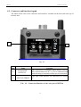
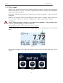
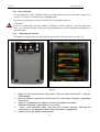
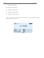
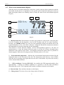
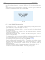
1
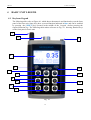
NHT-310
User Manual
!
!
!
!
!
!
!
!
!
!
!
!
!
!
!
!
!
!
!
!
!
!
!
!
!
!
!
!
!
!
!
!
!
!
!
Release 2.3
Design Development and Manufacturing
MICRORAD
P.zza delle Azalee 13/14
05019 Orvieto (TR) – ITALIA
Tel +39 0763393291
Fax +39 0763394423
email [email protected]
web www.microrad.it
February 2014
II
CONTENTS
1! General information ................................................................................................................................... 4!
1.1! Applications ............................................................................................................................................ 4!
1.2! About the instrument ............................................................................................................................... 4!
1.3! Operating modes ..................................................................................................................................... 4!
1.3.1! Single EMF measurements ......................................................................................................... 4!
1.3.2! Long term monitoring ................................................................................................................. 5!
1.3.3! NHT310 remote control using MicroLink software ................................................................... 5!
1.3.4! Downloading data from NHT310 to PC using MicroLink software ........................................... 5!
1.4! Measurement probes ............................................................................................................................... 6!
1.5! GPS module and temperature sensor ...................................................................................................... 6!
1.6! Items included ......................................................................................................................................... 7!
1.7! Technical specifications .......................................................................................................................... 8!
1.7.1! NHT310 unit specifications ........................................................................................................ 8!
1.7.2! Measurement probes ................................................................................................................... 9!
1.8! Standards compliance ............................................................................................................................. 9!
2! Safety Summary ...................................................................................................................................... 10!
2.1! Foreword ............................................................................................................................................... 10!
2.2! Correct use ............................................................................................................................................ 10!
3! Certification and Warranty ...................................................................................................................... 11!
3.1! Certification .......................................................................................................................................... 11!
3.2! Warranty................................................................................................................................................ 11!
3.3! Limitation of Warranty ......................................................................................................................... 11!
4! basic unit LEGEND ................................................................................................................................. 12!
4.1! Keyboard legend ................................................................................................................................... 12!
4.2! Connector and Interface legend ............................................................................................................ 15!
5! Preparation for use ................................................................................................................................... 17!
5.1! Unpacking ............................................................................................................................................. 17!
5.2! Storage .................................................................................................................................................. 17!
5.3! Connecting the probe ............................................................................................................................ 17!
5.4! Power supply ......................................................................................................................................... 18!
5.4.1 Operating time ............................................................................................................................. 19!
5.4.1! Replacing the batteries .............................................................................................................. 19!
6! Operation ................................................................................................................................................. 20!
6.1! Switching on ......................................................................................................................................... 20!
6.2! Main screen measurement display ........................................................................................................ 23!
6.3! Recording measured values. ................................................................................................................. 25!
6.3.1! Single value storing. .................................................................................................................. 25!
6.3.2! Storing Multiple Values (monitoring). ...................................................................................... 26!
6.4! Data transfer and display....................................................................................................................... 28!
6.5! Spatial Average Mode ........................................................................................................................... 28!
6.6! Alert level .............................................................................................................................................. 28!
6.7! Factory reset. ......................................................................................................................................... 29!
7! MicroLink SOFTWARE ......................................................................................................................... 30!
7.1! Description ............................................................................................................................................ 30!
7.2! Software installation ............................................................................................................................. 30!
7.3! Main screen ........................................................................................................................................... 31!
7.4! Functions ............................................................................................................................................... 32!
7.5! Configuring parameters on NHT310 unit (Settings)............................................................................ 33!
7.6! Downloading data from NHT310 unit (Download) ............................................................................. 35!
7.6.1! Snapshots ................................................................................................................................... 36!
7.6.2! Monitoring ................................................................................................................................. 37!
7.6.3! “Plot” section ............................................................................................................................ 39!
7.7! Exporting data to Microsoft Office Excel™ (Export) .......................................................................... 41!
7.8! Remote control of NHT310 unit (Remoting) ........................................................................................ 42!
7.9! GPS and Google Maps .......................................................................................................................... 42!
7.10! Firmware update of NHT310 unit (Fw Update)................................................................................. 44!
III
NHT310
1
1. General information
GENERAL INFORMATION
1.1 Applications
Human exposure to electromagnetic fields (not ionizing radiation) is nowadays a critical subject
that all countries must address. Technical and normative bodies work alongside government
institutions to enact new guidelines and norms regarding maximum permitted exposure levels
for populations and workers.
Measurement equipment for this type of analysis must comply with the technical requirements
from industry guidelines and must provide the user with appropriate indications for comparison
with legally required thresholds.
1.2 About the instrument
The NHT 310 is a new Microrad solution for the measurement and analysis of of
electromagnetic field (EMF) safety applications.
This portable and compact instrument operates in the widest possible frequency bands for a
handheld unit. The NHT 310 is user-friendly and provides very reliable measurements; it also
provides the user with the temperature reading of the surrounding environment as well as the
GPS coordinates of the site being measured both of which can be included in the user’s final
report.
1.3 Operating modes
1.3.1
Single EMF measurements
Main application of NHT310 is to execute single EMF wideband measurements. The system
can utilise a number of different probes depending on the physical parameter being measured
(magnetic induction, magnetic field and electric field)and frequency band required.
The LCD screen displays the following information:
! Immediate isotropic value (ISO) of measured field level.
! Time Average isotropic value (AVG) of measured field level.
! Spatial Average isotropic value (SPT) of measured field level.
! Maximum isotropic value (MAX) of measured field level.
! Alarm threshold (ALM).
! Geographic coordinates (GPS).
! Environmental temperature.
! Date and time.
4
NHT310
1. General information
The instrument can be used in standard mode operating directly through its keyboard located on
the front of the device. The acquisition of single measurement values is always made by the
user command [STORE SINGLE]. Every single value is stored in a specific memory partition
reserved for single measurements (total 432 values) in conjunction with general information
regarding date, time, GPS coordinates, environmental temperature and single axis X, Y, Z
levels.
1.3.2
Long term monitoring
The NHT310 allows the user to perform up to 8 data acquisition sequences for long term
monitoring of wideband electromagnetic fields. This operating mode can be useful when
conducting low frequency B measurements since it allows the user to track the daily
fluctuation of B-field values based on the flux in the electrical lines or transformer stations
(field sources).
To start the acquisition sequence the user simply presses the key [SHIFT]" first" and" then"
[MONIT] key.!!
The monitoring lasts until the specific memory partition or bank is full (up to 21.500 values) or
until the user presses any key to interrupt the activity.
1.3.3
NHT310 remote control using MicroLink software
This operational mode is recommended in situations where the user is conducting electric field
analysis and wishes to avoid any interference that may occur from other sources e.g. the user’s
own magnetic field which may have an influence on the field being measured or, when there is
a request to install the measuring system in a screened and controlled space such as an
anechoic chamber for EMC testing. In such a situation it is strongly recommended that a
wooden tripod with variable height (optional accessory)be used.
The NHT 310 can be managed in remote mode through a fiber optic connection (transparent
non conductive material) which is connected to an external PC / Tablet running the MicroLink
software (provided as standard) on the PC. Microlink software (installed on the PC / Tablet)
allows the user total remote control of the NHT 310 unit replicating its screen and keyboard on
the PC monitor. This feature makes the entire system very easy to use. The software processes
the measured values in real time and simultaneously shows in graphic form the Amplitude vs
Time curve of the field being analysed.
In remote mode it is possible to store single values or to start and stop monitoring sequence
events.
1.3.4
Downloading data from NHT310 to PC using MicroLink software
All measurements taken, recorded both as a single stored acquisitions (punctual) and as a long
term monitoring event must be downloaded to an external PC through fibre optic cable and
MicroLink software in order to be viewed and analysed.
The software allows the user to view the acquired data in numeric and tabular format and
presents the information graphically in a signal vs time context which can utilise a zoom
function for obtaining more detailed information of the area of interest.
5
NHT310
1. General information
The data tables can be saved in MS Excel format while the data charts can be saved in jpeg or
bitmap format files.
In addition, it is possible to send configuring parameters to NHT310 unit for setting the acoustic
alarm level, setting the sampling time in long term monitoring, setting the time interval for
calculating the AVG value with high frequency probes (6 minutes as default value in
accordance with International Laws), setting date and time.
Furthermore, MicroLink software enables the processing of a 24h moving average (for this kind
of processing the monitoring sequence must obviously exceed a one day period).
1.4 Measurement probes
Several measurement probes are available to be used in conjunction with NHT310, both for
magnetic and electric field measurement, from dc up to 40 GHz.
Each probe is automatically recognised by the NHT310 when inserted.
See paragraph 1.7.2 for a detailed list of the NHT310 available probes.
1.5 GPS module and temperature sensor
The NHT 310 incorporates a GPS module which acquires geographic coordinates identifying
the site where the measurements were registered. In the case of outdoor activities it is always
recommended that the user includes the GPS data related to the test site so they may be
included in the final report.
This feature is particularly useful when evaluating:
! EMF background around new radio base stations.
! Environmental impact of transformer stations.
! Exposure mapping of an extended geographical area .
No additional devices are required when carrying out these measurements as the NHT310
performs these tasks automatically. It provides both the field measurement values and GPS
coordinates of the site. The MicroLink software allows the user with to display the
coordinates on Google Maps™.
In addition NHT310 incorporates a temperature sensor which acquires the temperature value
during the measurement activity. Since the sensor is installed in the front section of the
instrument it is recommended that the temperature value be accepted only if the unit is installed
on a tripod and not in the operator’s hand. The shell of the meter is made from magnesium and
may therefore conduct heat from the user’s hand thus influencing the temperature value being
measured
6
NHT310
1. General information
1.6 Items included
The standard NHT310 unit is delivered with the following components:
! NHT310 basic unit for measuring, storing and display field data
! Fiber optic cable (10 meters length)
! Fiber-USB-adapter to link fiber optic to PC
! USB A/B adapter cable
! Battery charger
! Rechargeable battery (4xAA)
! MicroLink software available from www.microrad.it
In order to function correctly, the NHT310 meter must be connected to a measurement probe
from the Microrad range.
7
NHT310
1. General information
1.7 Technical specifications
1.7.1
NHT310 unit specifications
PROBE TYPES
Frequency range
DC to 40GHz with different E and B/H probes
DISPLAY
Display type
Transflective LCD monochrome COG (chip on glass)
Display size
7 cm , 128x64 dots
Backlight
Electroluminescent sheet switchable 10s/continuous
MEASUREMENT FUNCTIONS
Result units
mW/cm², W/m², V/m, A/m, Tesla
Display range
From 0.0001 up to 999999 depending on probe and selected unit
Result types (isotropic, RSS)
Actual (ACT), Maximum (MAX), Average (AVG), Median
Averaging time
6min std 4 s to 30 min (2 s steps), selectable by PC software
24h moving average processed by PC software
STORAGE MODE
Samples
21.504 (8 monitoring sequences) / 432 (snapshots)
INTERFACES
Optical interface
Serial, full duplex
Probe interface
Plug-and-play auto detection, LEMO™ connector
Analogue interfaces
3 separate outputs X, Y, Z SMA connectors
GPS
Model
FALCOM FSA03 quadrifilar helix
Receiver
50 channels, tracking L1 C/A code, update rate 4Hz, NMEA
Time to first position (TTFF)
Cold start 29 sec, warm start 29 sec, hot start < 1 sec
Sensitivity
Tracking -160dBm, autonm. acquisition -144dBm
GENERAL SPECIFICATIONS
Recommended calibration interval
24 months
Battery
NiMH rechargeable batteries, 4 x AA size (Mignon), 2800 mAh
Operation time
Approx. 72 hours (backlight off)
Charging time
4 hours
Battery level display
100%, 66%, 33%, < 10%
Temperature range
Operating -10 °C to +50 °C
Non-operating (transport) -20 °C to +70°C
Humidity
5 to 95%, non condensino
Size (h x w x d)
160 x 98 x 30 mm (without probe)
Weight
approx 400 g (including batteries without probe)
Accessories (included)
Hard case, AC charger, rechargeable batteries, PC software,
fiber optic (10m), USB-Optical Converter, operating manual,
!
probe/s calibration certificate
Note: technical specifications are subject to change without prior notice.
8
NHT310
1. General information
1.7.2
Measurement probes
Radiofrequency field probes
P/N Probe
Frequency range
Type of freq. response
Measurement range
Directivity
01E
02E
02H
03E
04E
100 KHz - 6.5 GHz
400 KHz - 30 MHz
300 KHz - 30MHz
100 kHz - 18GHz
3 MHz - 40GHz
Flat
Flat
Flat
Flat
Flat
0.2 - 350 V/m
2 - 800 V/m
0.016 - 16 A/m
0.8 - 340 V/m
0.5 - 350 V/m
Isotropic
Isotropic
Isotropic
Isotropic
Isotropic
Rec. calibration interval
24 months
24 months
24 months
24 months
24 months
Operating temperature
0°C - 50°C
0°C - 50°C
0°C - 50°C
0°C - 50°C
0°C - 50°C
Low frequency field probes
P/N Probe
Frequency range
Type of freq. Response
Measurement range
Directivity
11E
10B
20B (100 cm2)
30B (100 cm2)
5Hz - 400 KHz
5 Hz - 400 KHz
5 Hz - 20 KHz
5 Hz - 400 KHz
Flat
Flat
Flat
Flat
20 V/m - 20KV/m
0.1 µT - 1 mT
0.3 µT - 16 mT
0.3 µT - 16 mT
Isotropic
Isotropic
Isotropic
Isotropic
Rec. calibration interval
24 months
24 months
24 months
24 months
Operating temperature
0°C - 50°C
0°C - 50°C
0°C - 50°C
0°C - 50°C
20H
30H
DC - 1 KHz
DC - 1 KHz
Flat
Flat
1 mT – 15 T
200 µT - 600 mT
Static field probes
P/N Probe
Frequency range
Type of freq. response
Measurement range
Directivity
Isotropic
Isotropic
Rec. calibration interval
24 months
24 months
Operating temperature
0°C - 50°C
0°C - 50°C
Note: technical specifications are subject to change without any prior notice.
1.8 Standards compliance
Electrical equipment for measurement, control and laboratory use. EMC requirements:
radiating emission, radiating immunity in radio frequency, electrostatic discharge.
CEI EN 61326
SAFETY
Safety requirements for electrical equipment for measurement, control and laboratory use –
General requirements.
CEI EN 61010
CE mark
European Union
YES
Country of origin
ITALY
ESD and EMC
9
NHT310
2
2.1
1. General information
SAFETY SUMMARY
Foreword
The following general safety precautions must be observed during all phases of operation,
service, and repair of this instrument. Failure to comply with these precautions or with specific
WARNINGS elsewhere in this manual may impair the protection provided by the equipment.
Such noncompliance would also violate safety standards of design, manufacture, and intended
use of the instrument.
2.2
Correct use
• Keep away from live circuits
Operators must not remove instrument covers. Component replacement and internal
adjustments must be made by qualified maintenance personnel. Do not replace components with
the power cable connected. Under certain conditions, dangerous voltages may exist even with
the power cable removed. To avoid injuries, always disconnect power and discharge circuits
before touching them.
• DO NOT substitute parts or modify instrument
To avoid the danger of introducing additional hazards, do not install substitute parts or perform
unauthorized modifications to the instrument. Return the instrument to Microrad Service Center
for service and repair to ensure that safety features are maintained in operational condition.
10
NHT310
3
3.1
1. General information
CERTIFICATION AND WARRANTY
Certification
Microrad certifies that this product met its published specifications at the time of shipment from
the factory. Microrad further certifies that each probe of NHT310 instrument has been
calibrated according to DIN EN ISO 9001:2008 rules. On request is also available a calibration
certificate traceable on 17025 standard, concerning electric and magnetic field strength, and
electromagnetic power density for the high frequency range.
3.2
Warranty
This Microrad product is warranted against defects in material and workmanship for a period of
24 months (basic unit and probes). Accessories are warranted for a period of 6 months. During
the warranty period, Microrad will, at its option, either repair or replace products that prove to
be defective.
For warranty service or repair, this product must be returned to Microrad.
User shall prepay shipping charges to Microrad and Microrad shall pay shipping charges to
return the product to User.
Microrad warrants that software and firmware designed by Microrad for the instrument use will
execute its programming instruction when properly installed on that instrument.
3.3
Limitation of Warranty
The foregoing warranty shall not apply to defects resulting from improper or inadequate
maintenance by User, User-supplied software or interfacing, unauthorized modification or
misuse, operation outside the environmental specifications for the product, or improper site
preparation or maintenance.
11
NHT310
4
4. Basic Unit Legend
BASIC UNIT LEGEND
4.1 Keyboard legend
The following table refers to Figure 4.1 which shows the numeric and function keys on the front
panel of the base unit. Some keys have a second function indicated in blue and can be enabled
by pressing the [SHIFT] key (located in the middle of the keypad ) before pressing the
required function key. The following table makes reference to Fig. 4.1 showing function keys
on the front panel of basic unit.
1
2
3
4
5
12
6
13
7
8
9
14
10
11
15
Fig. 4.1
12
NHT310
4. Basic Unit Legend
Item
Device Key
Function
1
GPS antenna
2
Probe connector
3
Battery charger input
4
Display and Backlight
5
Temperature sensor
MODE key
6
Standard: changes measurement unit
SHIFT enabled: shows single axes X, Y, Z
STORE key
7
Standard: stores a single value
SHIFT enabled: starts monitoring
LIGHT key
8
Standard: temporary back light of display
SHIFT enabled: continuous back light of display
SHIFT key
9
Enables all blue defined functions
POWER key
10
Switches on and off the instrument
GPS key
11
12
Enables and Disables GPS module
Blue LED of battery charging in progress
13
NHT310
4. Basic Unit Legend
RESET key
13
Standard: reset of time average (AVG)
SHIFT enabled: reset of MAX value measured
ALARM key
14
Enables and disables acoustic alarm which is triggered
when exposure threshold has been exceeded
FILTER key
15
Enables and disables a filter dedicated to low frequency
probes
Tab. 4.1 – Keyboard legend
14
NHT310
4. Basic Unit Legend
4.2 Connector and Interface legend
The tables below refer to the connectors and interfaces available on the back and at the top of
the base unit.
1
2
Fig. 4.2
Item
1
2
Name
ANALOGUE
OUTPUTS
OPTICAL/SERIAL
Function
SMA connectors for analogue signal outputs from the
three measurement axes X, Y, Z to be connected and
analyzed using an external oscilloscope (not included)
Fibre optic cable interface for connection to a remote
PC
Tab. 4.2 – Connectors/Interfaces on the rear part of NHT310
15
NHT310
4. Basic Unit Legend
1
2
Fig. 4.3
Tab. 4.3 – Connectors/Interfaces on the upper side (Fig. 4.3)
Item
Name
1
LEMO
2
BARREL JACK
Function
Input connector for measurement probe
Battery charger input
16
NHT310
5
5.1
5. Preparation for use
PREPARATION FOR USE
Unpacking
As soon as the instrument arrives at destination , please carefully check the packages to verify
possible damages caused by shipment. If any damage is found, inform Microrad immediately.
It is recommended to keep the original packages for a future shipment due to, for instance,
repairing or setting.
5.2
Storage
After the material contained in the packages has been inspected and verified for damages, it
should be kept stored in its original packing until the time of installation. The storage deposit
must be well protected and free from humidity.
Avoid keeping the material in storage for a long time since this may cause some failures during
the initial period of utilisation.
If the instrument should be kept in storage for a long time, it is advisable to insert hygroscopic
substances (such as silicon gel salts) in the package.
5.3 Connecting the probe
The probe is equipped with a LEMO “Push/Pull” connector. To connect it to the NHT310 unit,
push the probe plug straight down into the probe socket until it clicks into place (the red mark
on the probe plug must point towards the red mark on the unit socket).
To disconnect the probe, slide the sleeve on the probe plug upwards and pull the probe upwards
to remove it.
Probe Sleeve
Fig. 5.1
17
NHT310
5. Preparation for use
5.4 Power supply
NHT310 can operate both powered by NiMh rechargeable batteries (included as standard) and
alkaline dry batteries (4 x AA). The battery charger must be used to recharge the rechargeable
batteries provided as standard.
During the recharging cycle the system cannot be powered up and therefore cannot be used for
measuring.
Batteries are normally delivered fully charged but may require a complete charge before first
time operation of the unit. A complete recharging cycle requires approximately 4 hours.
• WARNING
Never connect the battery charger if dry batteries are installed! This procedure may
result in significant damages to the instrument!
Disregarding the above rules causes the warranty expires!
Battery charge status is always indicated in upper right corner of the display in each operating
mode.
Fig. 5.2
During the recharging cycle a blue led indicator appears in the top right hand corner of the
display.
Fig. 5.3
18
NHT310
5. Preparation for use
5.4.1 Operating time
The operating time of the standard batteries provided with the system when fully charged is in
excess of 72 hours of continual use (backlighting off).
Dry battery operating times may exceed those of rechargeable batteries.
WARNING
Never use rechargeable batteries which are different to those supplied with the instrument.
Note: use of battery chargers different to that supplied may result in damage to both batteries
and instrument.
5.4.1
Replacing the batteries
The battery compartment is located under the rear panel of the instrument (see Fig. 5.4).
Fig. 5.4
1. Switch off the instrument and disconnect it from all other devices (AC Charger,
USB adapter).
2. Open the battery compartment at the back of the instrument using the appropriate
screwdriver.
3. Remove old batteries and dispose of them according to the waste
disposal ordinances applicable in your country.
4.
Insert new batteries. Make sure they are inserted correctly following the
instructions in the diagram located within the battery compartment.
5. Securely close the battery compartment.
19
NHT310
6
7. MicroLink software
OPERATION
6.1 Switching on
Press [POWER ON] key (Tab. 4.1). The instrument starts an auto-test cycle, and displays
partial device data.
Fig.6.1 shows the first screen displayed at power on, reporting the identification data of the
instrument.
1
2
3
4
Fig. 6.1
1 – P/N. NHT310 Part Number.
2 – S/N. NHT310 Serial Number.
.
3 – Prd. NHT310 production date.
4 – Fw. Firmware version running on the instrument.
Fig.6.2 shows the second screen displayed after the power on, reporting memory status
information and the setting of some parameters.
20
NHT310
7. MicroLink software
5
6
7
8
Fig. 6.2
5 – Snaps. Number of single measurements stored in the NHT310 internal memory.
6 – Monit. Residual recording time for the monitoring function, updated according to the
monitoring sample time parameter (Tsamp).
.
7 – Tsamp. Sample time parameter at the moment set for the monitoring function.
8 – Tavg. Time parameter at the moment set for the processing of the mobile window average
function.
Once the power-on information sequence has terminated and a probe has been inserted into the
instrument the following information will be displayed (see fig 6.3).
The same information is displayed each time a probe is connected to the instrument; this
information remains visible on the screen for a few seconds.
9
5
11
0
13
0
10
0
12
0
Fig. 6.3
21
NHT310
7. MicroLink software
9 – P/N. Probe Part Number.
10 – S/N. Probe Serial Number.
.
11 – Prd. Probe production date
12 – Cal. Probe calibration date.
13 – Typ. Probe frequency interval.
In the case where there is no probe inserted in the device, then the following message is
displayed on the screen (Fig. 6.4).
Fig. 6.4
22
NHT310
7. MicroLink software
6.2 Main screen measurement display
After the power on operation and probe connection, a probe warm-up phase commences and the
time taken for this process is dependent on the specific probe being used (during the warm-up
phase the display shows zero blinking values), finally the main screen measurement appears
(Fig.6.5).
10
0
11
0
5
1
6
2
7
3
8
9
4
Fig. 6.5
1 – Measurement unit. By default the unit shows the parameter related to the connected probe
(V/m for E-probes, µT for B-probes, A/m for RF H-probes and mT for static H-probes).
Pressing the [MODE UNIT] key, the user can sequentially change the default unit to the
required alternative (V/m, A/m, W/m², mW/cm²). Using this function the instrument calculates
the mathematical conversion applying specific algorithms.
This function is useful when for example the far field hypothesis applies to the place of
measurement (i.e. when the distance from the source is at least 2d²/ λ where d=longest linear
dimension of the antenna source and λ= wavelength of measured signal); then it is possible to
obtain magnetic field value (H) using an electric field (E) probe or vice-versa.
2 – Environmental temperature. Indicates the environmental temperature measured by the
integrated sensor on the front part of the unit. The temperature value shown is more reliable
when the unit is operating on a tripod and not in the user’s hand which may affect the accuracy
of the measurements obtained.
3 – GPS coordinates. Pressing [GPS ON] key enables the GPS integrated module; after
approximately 2 minutes in outdoor conditions it is possible to read the GPS coordinates
identifying the test site. The Longitude and Latitude coordinates alternate on the display.
4– Date and time. Date and time alternate on the display.
5 – Charge status. This icon refers to the charge status of batteries.
23
NHT310
7. MicroLink software
6 – Measured value. It is the immediate isotropic measured field value.
7 – AVG value. This indicator displays the square mean value (average) in a mobile time slot.
To reset this value press [RESET AVG]. The default time slot for this AVG value is 6 minutes.
This value can be changed through the MicroLink software. The AVG value remains empty
until the configured AVG time has elapsed since power- on or since the last AVG reset. As
soon as it becomes available the AVG value is continuously updated (mobile average) with
new measured samples being added to the calculation and old ones deleted. This allows for the
calculation of a dynamic average of a fixed number of samples.
8 – MAX value. Displays the maximum value which has occurred since the device has been
switched on or since its last reset. This value is updated only if a higher value occurs. To reset
this value press [RESET MAX].
9 – ALM level or SPT value. Pressing the [ALARM ON] key, the threshold value for
activating a warning acoustic alarm appears. This threshold can be configured through the
MicroLink software. The user may alternate between alarm level and space average value
(SPT) values which are indicated in the same physical space in the display.
10 – LPF filter. By pressing the [FILTER ON] key when a low frequency probe (i.e. probe
such as the 10B, 11E,), is plugged into the device the message LPF is shown. A second order
Low Pass Filter (40dB/dec) with cutoff frequency at 1KHz is enabled. This may be useful for
example when measuring 50Hz sources with some related harmonics, thus cutting out higher
frequency sources. Below the filter diagram (Fig. 6.6):
Fig. 6.6
24
NHT310
7. MicroLink software
In the case of static field probes (i.e. 20H, 30H) the filter acts as a first order High Pass Filter (20
dB/dec) with cut-off frequency around 1.5Hz; filter activation is highlighted by the HPF message
on the display. Essentially the filter cuts the DC component out of the signal, thus allowing the user
to discriminate between static components and higher frequency magnetic fields.
11 – SHIFT. This indicator appears after pressing the [SHIFT] key, meaning that all the blue
functions on the keyboard are selectable .
12 – X, Y, Z. this values represent the X, Y, Z field components (Fig. 6.7). They take the place of
the AVG, MAX and ALM values after pressing the [MODE AXES] key.
12
0
Fig. 6.7
6.3 Recording measured values.
The user can record the measured values using two different ways:
• Manual storing of the single measured value.
• Automatic storing of a measurement sequence (monitoring).
The instrument reserves two different memory spaces for the two recording modes.
Available space for single measured value: 432 measurements.
Available space for monitoring sequence: 21.504 measurements.
6.3.1
Single value storing.
Each time the user wishes to save preliminary values and to immediately record /acquire what
the display shows he just has to press the [STORE SINGLE] key. This action stores the
instantaneous measurement value together with related display data (ISO, X, Y, Z values, time,
25
NHT310
7. MicroLink software
date, GPS coordinates when active, temperature, MAX value, AVG value when available, probe
data).
During this storing process the display shows the message as shown in Fig. 6.8; it informs the
user about the actual number of stored values vs total available.
Fig. 6.8
6.3.2
Storing Multiple Values (monitoring).
The instrument can execute a time continuous monitoring activity recording measured values
from a START time to a STOP time which is user defined.
The sampling time for this function defaults to 5 seconds but it can be easily changed through
the MicroLink software.
One sample is essentially a tern of X, Y, Z field value. Temperature and the initial GPS
position (when available) are stored.
Note that GPS and backlight should be switched off when monitoring starts in order to
conserve the life of the battery.
The instrument allows the user to store up to 8 different monitoring sequences. However the
sum of all the samples from all the sequences cannot exceed 21.504 samples.
The monitoring recording sequence begins after pressing [STORE MONIT].
Then the instrument starts a countdown (defaults to 15 seconds but user can change it using
MicroLink software) before beginning the storing sequence allowing the user to distance
himself from the unit and avoiding creating undesired EM disturbances during the
measurement process.
During the countdown the number of the monitoring sequence (1..8) is displayed. (Fig. 6.9).
If needs be it is possible to abort the countdown sequence by pressing any key.
26
NHT310
7. MicroLink software
Fig. 6.9
During recording, the screen shows the current monitoring sequence number (1÷8), the
sampling time, the elapsed time from when the recording commenced, and a dynamic indicator
bar which proportionally increases in length according to the number of samples stored in
memory and remaining space available(Fig. 6.10) .
An empty bar indicates that no samples have been acquired. (No monitoring has taken place) –
Full memory corresponds to 21.504 samples.
Fig. 6.10
The device will continue monitoring until the memory bank is full (i.e. the bar is full) or the
user wishes to stop or interrupt the monitoring process which he may do by pressing any key. If
the unit memory already contains 8 monitoring sequences or 21.504 sample, and the user
attempts to start a new recording sequence, a message MEMORY FULL appears on the
screen and the monitoring is cancelled.
In order to restore the monitoring capability, the user must download to the PC and then clean
all the data using the MicroLink software, or perform a hard reset as shown at paragraph 6.7.
Alternatively the user may start and/or stop a monitoring sequence using the programmed time
function set within the MicroLink software; this function allows the user to set the monitoring
start and stop time. Activation of this function is shown on the screen by a blinking * character
positioned near the ISO value just recorded.
27
NHT310
7. MicroLink software
6.4 Data transfer and display.
In order to show the recorded data , the data must first be transferred to a PC through the fiber
optic cable, the Fibre-USB-adapter and the MicroLink software included in the standard
package.
See chapter 7 MicroLink software for the detailed procedure.
6.5 Spatial Average Mode
By pressing the [STORE SINGLE] key holding it down for about 4 seconds the user can enter
the Spatial Average Mode; the same operation can be repeated to return to the standard mode.
When this special mode is enabled, the message MODE SPATIAL AVERAGE appears in the
location which is usually reserved for temperature, GPS, date and time (Fig.6.11).
It is now possible to save single values by pressing [STORE SINGLE] (as described in chapter
6.3.1) and an SPT indicator is displayed on the screen providing the square average value
calculated using /on all the N single instantaneous values stored.
This function is of particular use when the user wishes to quickly obtain the average of two or
more values acquired in different spatial points.
Fig. 6.11
Note that the SPT average value is also displayed in standard mode, and the user may switch
between this reading to the ALM alarm threshold. Moreover the SPT average value is not
cleared when the instrument is power down, it remains in memory; it is cleared only when the
user enters the spatial average mode.
6.6 Alert level
28
NHT310
7. MicroLink software
The NHT310 features a function which warns the user by way of an acoustic signal that the
field being measured exceeds a threshold level which has been assigned by the user through
the MicroLink software; this alert function is enabled by pressing the [ALARM ON] key.
In addition to this function which is configured by the user, the NHT 310 alerts the user when
the measured field exceeds the 95% of the range of the probe. This is accomplished by
displaying both an E character (Fig.6.9) and by the use of acoustic signals. The E character
always appears near the isotropic value and also near the axis which has exceeded 95% of
range limit of the probe being used.
Fig. 6.12
Finally, when the field strength exceeds 100% of the range of the probe a message indicating
“OVER-RANGE” (Fig.6.10) appears on the screen in place of the isotropic value; this message
is always accompanied by an acoustic signal.
Fig. 6.13
6.7 Factory reset.
To perform a factory reset on NHT310 unit, press the [RESET AVG] key and hold for 10
seconds.
This action will erase all measurement data and will restore all NHT310 parameters to
factory default.
29
NHT310
7
7. MicroLink software
MICROLINK SOFTWARE
7.1 Description
The Microlink software, included in the standard package, has three main functions.
The first is to allow the user to configure the instrument’s parameters which control; average
value processing, monitoring function, alert threshold and clock time .
The second function is to allow downloading, storing and displaying of data on a PC utilising
tables and charts for final report generation. This data can be exported using Microsoft Excel™
format.
The third function allows the user to remotely manage the NHT310 unit from an external
PC connected through the fibre optic cable. This mode is useful if the user needs to perform
measurements (e.g. safety measurements, EMC test in anechoic chamber) when the unit is
installed on a tripod and the user is required to check the measurement progress from a distance
in order to avoid potential EM disturbances to the field being tested. In remoting mode it is
possible to configure several parameters.
7.2 Software installation
MicroLink runs on Windows XP, Windows Vista, Windows 7, Windows 8, 32 e 64 bit.
This software is available for download from www.microrad.it
Clicking on the .exe setup file, the software is installed on the PC.
During the installation process, the drivers for USB/Optical adapter are also installed to enable
the recognition of the USB/Optical adapter each time it is connected to the PC.
The installation process takes a few minutes.
At the end of the installation a new MicroLink icon will automatically be created on the desktop
and Window menu.
30
NHT310
7. MicroLink software
7.3 Main screen
Fig. 7.1
The program functions are included in the menu bar located on the upper part of the screen as
follows:
File
- [Open] [Save] [Properties] [Exit]
Meter - [Download] [Settings] [Remoting] [Fw Update]
Data - [Export] [Units] [Print]
Help
- [Contents] [About]
All mentioned functions are also easily accessible through the icons located just under the
menu bar (except for the Fw Update and Exit functions) .
When the NHT310 unit is not connected to the PC, a No Device message appears in the lower
right corner of the screen.
When connecting to the NHT310 and trying to establish communications with the unit or
when the MicroLink application is opened a communications window opens and informs the
user that communication between the devices has /has not been successful.
In the lower left corner of the screen the message No File Loaded is displayed until such time
as a measurement file has been opened or saved on the PC.
After recalling a file, its name and path are shown in the lower left corner of the screen.
31
NHT310
7. MicroLink software
7.4 Functions
Open – Opens measurement files
already stored on a PC storage units.
Save – Saves a measurement file on a PC storage
unit.
Properties – Displays connected NHT310 unit
information.
Download – Downloads measurement values from
NHT310 unit.
Settings – Sets NHT310 parameters.
Remoting – Remotely connects PC to NHT310 unit
through fiber optic link for control purposes .
Export – Exports measurement data to Microsoft
Office™ Excel compatible format.
Units – Sets Default unit selection. for EMF and
temperature.
Print – Prints requested output.
Contents – Opens this user manual.
About – Regards software release information.
32
NHT310
7. MicroLink software
7.5 Configuring parameters on NHT310 unit (Settings)
By clicking on [Settings] icon, the user can access a configuration window (Fig.7.2) which
contains a number of NHT310 modifiable parameters. These parameters include:
• RMS Average : time interval for AVG calculation
• Monitoring : start/stop time and store sampling time
• Alarm Level: threshold level for acoustic alarm
• Date & Time: date and time on NHT310 unit
Fig. 7.2
The user may modify the parameters from the control panel as follows:
RMS Settings
Configuration of the time interval for the AVG calculation
(time average). The default value is 6 minutes according
with International laws and guidelines.
This configuration is important for high frequency
measurements.
Fig. 7.3
33
NHT310
7. MicroLink software
Monitoring Settings
Configuration of:
•
•
•
•
•
time interval between one acquisition and the
following (sampling time) from 1 up to 30s;
delay time from start (Start Delay);
time programmed monitoring Enable;
date and time of monitoring start (Start Time);
date and time of monitoring stop (Stop Time).
Fig. 7.4
Alarm Settings
Configuration of the alarm threshold for strong field level.
•
•
•
High Frequency Probe: level and measurement unit
when high frequency electric (E) and magnetic (H)
probes are applied;
Low Frequency Magnetic Probe: level and
measurement unit when low frequency (B) probe is
applied;
Low Frequency Electric Probe: level and
measurement unit when low frequency (E) probe is
applied.
Fig. 7.5
Meter Clock Settings
Configuration of date and clock time on NHT310 unit.
Fig. 7.6
34
NHT310
7. MicroLink software
7.6 Downloading data from NHT310 unit (Download)
After connecting NHT310 to the PC through the fibre optic cable and adapter, click the icon
[Download].
The download starts and a progress bar appears during the download (Fig.7.7).
At the end of the download process it is possible to save measurement data on a PC drive unit.
This action is not mandatory since it can be done also later clicking on the icon [Save].
This activity allows the user/system to clear the NHT310 unit’s memory bank.
Fig. 7.7
Using the [Open] command it is possible to recall previously saved data file (.uR extension).
After data has been downloaded or after a save file has been opened, a window within the
MicroLink programme opens and shows a panel featuring three selectable tabs: SnapShots,
Monitoring, Plot.
35
NHT310
7. MicroLink software
7.6.1
Snapshots
SnapShots are the measurements stored manually one by one (single store).
Fig. 7.8
Each measurement (which corresponds to a table row) includes the following data :
•
Univocal progressive number (up to 432).
•
Date and clock time.
•
X axis, Y axis, Z axis instantaneous field value.
•
Immediate / Instantaneous Isotropic value (ISO).
•
AVG value (available only if the minimum interval time configured for time average
calculation has elapsed).
•
MAX isotropic value.
•
Temperature.
•
ON/OFF filter (only for low frequency measurements).
•
Measurement Probe information (by clicking on the specific field a windows appears
with data pertaining to the probe utilised during the measurement).
•
GPS Lock/Off (if the GPS is active and locked during the measurement, the text Lock
appears. By clicking on it, a window with the related coordinates appears. In addition
there is a Map icon that allows the user to view the GPS coordinates on Google Maps
(this function requires that the PC be connected to the Internet).
36
NHT310
7. MicroLink software
In this screen it is also possible to obtain a spatial average value (Spatial AVG) by simply
highlighting with a mouse at least 2 (or more) measurements and the Microlink software then
calculates the Spatial Average using the AVG value already available. This function is useful
for instance when the NHT310 unit is placed on a tripod and stores measurements at different
heights from the ground at the same site (as many technical guidelines suggest). The software
allows the user to choose the values from which he wishes to calculate the spatial average by
highlighting the values of interest and clicking on them while pressing the PC Control key
[CTRL]. The spatial average value will appear in the space just above the measurements list in
the Spatial Avg field.
Note that there is a difference between the spatial average performed by the NHT310 using the
spatial average mode (par.6.5) and the one calculated by the MicroLink software: the first takes
the instantaneous field value as input; the latter uses the time average value (AVG) already
processed by the NHT310.
7.6.2
Monitoring
The table (Fig.7.9) reports all the measured values stored using the monitoring function. Each
row contains a stored value.
Fig. 7.9
37
NHT310
7. MicroLink software
It is possible to store and keep in memory up to 8 monitoring sequences, which may be
selectable using the control on the top left corner, below the #Monitoring label.
The maximum quantity of rows is 21.504 considering all the sequences.
For each row/sample the following information are available:
•
Progressive numbers (starting from 1 up to 21504 until memory bank is completely
filled.
•
Date and time .
•
X axis, Y axis, Z axis instantaneous field value.
•
Instantaneous Isotropic value (ISO).
•
AVG value (in this case processed by the MicroLink software considers/utilises the
Tavg parameter value at the time of the monitoring start).
•
Temperature.
Data included by the report table headers provide some very useful data:
•
Monitoring Start and Stop date and time.
•
Sampling time (Tsample).
•
Number of acquired samples (Nsample).
•
UserStop indicates that a manual monitoring stop command has occurred ( e.g. the user
may have accidentally touched the instrument's keypad). As a result the last data
reading may be compromised due to the proximity of the user. Other means of halting
the monitoring process are by (a) by remote control, (b) allowing the instrument’s
memory bank to fill to capacity.
•
FilterStat reports the low frequency filter status during monitoring.
•
The Avg24h control allows the user to enable the 24h moving average in the Avg
column by setting Tavg= 24 hour. In this case there is a requirement for a monitoring
sequence longer than 24 hours.
•
The Time slot considered for the processing of the time average (Tavg), performed by
the MicroLink software.
•
Minimum (Min) and Maximum (Max) instantaneous isotropic values from the data
sequence.
•
Maximum of the average values (AvgMax).
•
Median index.
Note that the max average (AvgMax) index is displayed only when monitoring is performed
using radiofrequency field probes; vice versa Median index is calculated only when using low
frequency or static field probes.
38
NHT310
7. MicroLink software
Data regarding the probe and the GPS position related to the selected monitoring sequence are
accessible through the icons shown below (Fig.7.10). GPS time and space coordinates refer to
the place and the time at which the monitoring commenced.
Fig. 7.10
7.6.3
“Plot” section
This section allows access to a chart (Fig. 7.11) related to the sequence selected in the
monitoring data section (below the #Monitoring label).
Here the controls are placed on the left vertical bar:
•
Y Scale : this function allows the user to pass from a linear [Lin] field value scale to a
logarithmic [Log] one (except for temperature, always displayed using linear scale); in
case of logarithmic scale, the 0 dB value is dynamically assigned to the maximum value
of the instantaneous isotropic field; then every field value follows the formula:
E(dB) = 20 Log10 ( E / Eisomax )
•
Tracks : curves related to the [ISO], [AVG], [X], [Y], [Z], and temperature [T].
•
Marker : horizontal markers for maximum [Max] and minimum [Min] value for every
enabled track.
•
Tools : time zoom in [+], time zoom out [-] and [Export image] functions. Export
image saves the chart as a bitmap or jpeg image file.
39
NHT310
7. MicroLink software
Fig. 7.11
Note: the numeric value related to the points under the pointer are indicated when the moving
the mouse over the chart.
If the user wishes to highlight a specific portion of the screen and consequently the values
associated with it he may do so by dragging the mouse while holding down the left button over
the area of interest (Fig. 7.12).
Fig. 7.12
The image export function is accessed by clicking on the export image icon [Export image] a
window allows the user to make various choices (see Fig.7.13):
40
NHT310
7. MicroLink software
Fig. 7.13
The user can select the output file format .BMP or .JPG and choose to use the original chart
colors or he may wish to invert the color set (white on black rather than black on white) to
reduce the report printing costs.
7.7 Exporting data to Microsoft Office Excel™ (Export)
After downloading data, the user can save it on a PC drive unit by clicking on [Save] icon; in
addition it is possible to export the data in Microsoft Excel compatible format by clicking on the
[Export] icon. A window (Fig.7.14) enables the user to choose the characteristics of the data he
wishes to export for both types of measurement output, SnapShot and Monitoring.
The user may choose from the following: All data, Selection, None.
The user can then save the file as an .xls file.
Fig. 7.14
41
NHT310
7. MicroLink software
7.8 Remote control of NHT310 unit (Remoting)
After powering on the NHT310 unit and connecting it to a PC, the user can now remotely
manage all NHT 310 device functions by clicking on the [Remoting] icon. This activates a
double window on the PC monitor: in one window the software replicates the entire front side
of the instrument ; in the opposite window a real time chart is shown.
The NHT310 unit is easily controlled by way of a mouse which the operator uses to select the
required functions on the virtual NHT310 keyboard which is reproduced on the PC screen.
Fig. 7.15
It is important to remember that the real time chart is not automatically saved in remoting
mode. For every acquisition (single store or monitoring sequence) the user must execute the
[STORE SINGLE] or [STORE MONIT] as previously described.
7.9 GPS and Google Maps
If the GPS function is switched on during outdoor measurements and the position locked onto,
all of the downloaded data on the PC (snapshots and monitoring) will be associated with that
GPS information (time and coordinates). The user can then display this information using
Google Maps.
To visualise the GPS data on Google Maps, the user must verify that the computer is connected
to Internet, then click on the [Maps] button in the window below (Fig.7.16).
42
NHT310
7. MicroLink software
Fig. 7.16
The default system browser automatically opens the Google Maps webpage showing the
position on the map of the site being tested:
measurement point
Fig. 7.17
43
NHT310
7. MicroLink software
7.10 Firmware update of NHT310 unit (Fw Update)
The NHT 310 firmware can be upgrade simply by using the MicroLink software to install the
upgrade which can be downloaded from the microrad website. NHT 310 customers are
informed via e-mail when the latest firmware updates are released.
The file including a new firmware release has a suffix .rom and it can be received by email or
downloaded from manufacturer’s website www.microrad.it.
The following steps are necessary to start the update:
NHT310 unit preparation:
•
connect the NHT310 unit (which is powered down) to the PC through fibre optic cable.
•
Press the [RESET AVG] key and while holding it down, then press the ON/OFF
[POWER ON] key.
•
Release the ON/OFF [POWER ON] key while holding down the [RESET AVG] key
until the following message appears on the screen:
“FIRMWARE UPGRADE MODE”
•
Release the [RESET AVG] key.
•
MicroLink Software: after configuring the unit in update mode and starting the
MicroLink programme, click on [Meter] and [Fw Update].
•
A window opens and the unit is ready to load the updated file (this file .rom must be
stored on a PC driver unit in advance).
•
Click on the update file .rom and automatically starts the update procedure (it should
last approximately 30 seconds)
When the procedure is completed, a MicroLink message informs the user that the update of the
NHT310 is complete and the unit automatically reboots.
44