1
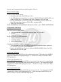
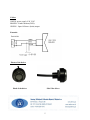
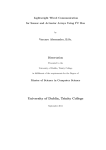
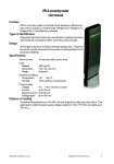
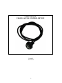
USER MANUAL USK1024 ACCES CONTROL DEVICE Version I. 26.07.2012 1 General information The device is dedicated to work with maximum 1024 Maxim Touch Memory DS19xx iButton keys. The key is a hermetically closed metal tablet with diameter of 17 mm and 6 mm high, with a Integrated Circuit inside. Each key has it’s unique code assigned . The number of possible combinations is 10 to the power 14. iButton keys have a high mechanical durability and a high resistance for EM influence. The device is placed inside the readers’ case. The reader is equipped with a LED indicator, which shows the state of the device. The concept of key registration is to allow a single key to work with any number of controllers. The programmed data of keys and the configuration mode of the device are stored In the EEPROM , therefore a lack of power supply has no affect on the stored data. Application USK 1024 is mainly dedicated to anti-theft intercommunication, access control system , steering for doors (EM hitch) and other receivers’ where load current does not exceed 2 Ampere. USK 1024 can be used in devices exposed to vibrations (if the loss of the connection between the reader and key is less then 1s, the device will still continue to work in chosen mode) State of the device (ON/OFF) is changed by touching the device with a previously programmed DS1990 Dallas iButton key. By eliminating keyboards and RF transmission a high degree of confidentiality was obtained. Technical data: Power Supply: 9 - 30V DC Max power supply pulse factor : 5% Max. electricity consumption : 30mA OC output: maximum load 2 A Working temperature -40 - +70°C Air Humidity: up to 80% Work environment : residential, commercial , lightly industrial Dimensions : diameter of the tread : Φ12mm; height of the tread : 15mm; diameter of the base of the reader: : Φ12mm high of the reader (from the base up to the ring) 14,3mm Maximum 1024 keys Maximum cable length : 200cm Build-in protection from polarity change. LED indicator states 3 possible working states 2 Storage: The device can be stored in a place with air humidity up to 80% and temperatures in rage from 45°C up to +80°C. Cooperating devices: DS1990 Dallas iButton keys Assembly: In order to assemble to device : 1. 2. 3. 4. 5. Unscrew the nut from the thread of the reader Take of the washer Shift the wires through the hole in the case. Shift the wires through the washer and the nut. Install the device by tightening the nut. Install the reader. First Activation The device has no programmed keys as default. Define two MASTER keys before first activation. If no MASTER key is remembered the device after powering the reader is ready to program. Yellow LED indicates the programming state. Define two keys in order to input the reader into programming state. Pulsating green LED light confirms memorising the keys , after which the system resets into the programming state allowing more keys to be memorised. Pulsating yellow LED indicates the device is expecting another key. First two memorised keys are MASTER keys. All others are SLAVE keys. WARNING!! MASTER keys are not functional for normal work. Only the SLAVE keys are able to perform inputted work mode. In order to simplify driver programming ,it is advised that the MASTER keys are TAH type. Adding and deleting keys A SLAVE key can be added at any time. In order to register a key follow the steps bellow: 1. Touch the reader with a MASTER key for a time no longer then 1s. 2. Yellow LED light indicates programming mode 3. To register a key touch the reader with a new key - its data will be remembered in EEPROM. It is signalised by double pulse green LED light. The device switches to programming mode – it is now possible to register or delete keys. OR To delete a key – touch the already assigned SLAVE key- its data will be removed from the EEPROM. A red LED light will switch on for 1s. The device switches to the programming mode – it is now possible to register or delete keys. WARNING!! It is not possible to delete a MASTER key following these steps. 4. To return to NORMAL mode touch the reader with a MASTER key for a second time 3 One key can be programmed into an infinite number of devices. Restore default settings In order to restore default settings : 1. Touch the reader with a MASTER key for 20 s 2. The LED indicator starts to pulsate in a sequence GREEN/YELLOW , GREEN-RED, one flash of GREEN for 1 s. The sequence ends with a continuous YELLOW light. 3. Erasing the EEPROM is possible by holding the MASTER key inside the reader. The light will change from continuous YELLOW to continuous RED 4. Take off the MASTER key All the MASTER keys will be deleted in this process as well. – go to FIRST ACTIVATION Configuration of the Device USK 1024 can work in three modes with programmable by the user time intervals (from 2 to 30 seconds ) bistable Touch and hold mode The device has three programming modes: adding / deleting keys work mode change restore default settings Changing the MODES is available at any time by: 1. Touch and hold one of the MASTER keys until the LED indicator starts to pulsate in a 0,5s internals of YELLOW and GREEN light. 2. Remove the MASTER key. The device returns to PROGRAMMING mode. The LED indicator shows YELLOW light. Switching to TAH mode: Touch the reader with a MASTER key (for a short period of time). The change of the MODE is signalised by GREEN LED light appearing for 1 s . The device is ready to work after a RED LED light appears. Switching to Monostable mode Touch and hold the reader with a MASTER key for a period of time that is to be assigned to the monostable mode. The programmed time can be from 2s up to 30s. ). The change of the MODE is signalised by GREEN LED light appearing for 1 s . The device is ready to work after a RED LED light appears. Switching to Bistable mode Touch and hold the reader with a MASTER key for longer then 30s . The change of the MODE is signalised by GREEN LED light appearing for 1 s .After removing the MASTER key the device is ready to work after a RED LED light appears. 4 Cables: WHITE- power supply 9-30 V DC BROWN - Earth/common (GND) GREEN – Open Collector (drain) output Example: Photos of the device Head of the driver Side if the driver 5