1
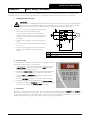
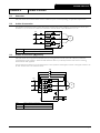
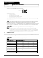
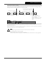
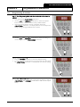
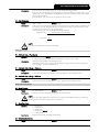
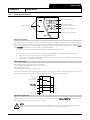
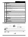
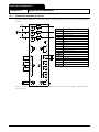
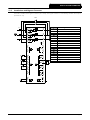
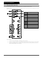
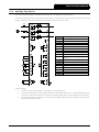
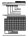
CONTROL CIRCUITS
Section 6
6.1
Control Circuits
Electrical Schematic
1
2
C23-C24
C31-C32
C41-C42
C53-C54
3
6.2
Control voltage
Remote control inputs
Start
Stop
Reset
Programmable input A
Thermistor input
4
5
13-14
23-24
33-34
41, 42, 44
6
RS485 serial interface
Relay outputs
Programmable output A
Run output
Programmable output B
Programmable output C
Analog output
Control Voltage
Voltage must be connected to the soft starter's control voltage terminals. The correct control voltage depends on the soft
starter model.
•
•
•
IMS2xxxx-xx-C12-xx-xx models: 110 VAC (A1-A2) or 230 VAC (A2-A3)
IMS2xxxx-xx-C24-xx-xx models: 230 VAC (A2-A3) or 400 VAC (A1-A2)
IMS2xxxx-xx-C45-xx-xx models: 460 VAC (A1-A2) or 575 VAC (A2-A3)
IMS2 Model
IMS20018 ~ IMS20047
IMS20067 ~ IMS20125
IMS20141 ~ IMS20238
IMS20253 ~ IMS20897
IMS21153 ~ IMS21574
6.3
Maximum VA
11 VA
18 VA
24 VA
41 VA
56 VA
Control Wiring
IMS2 operation can be controlled using the local control pushbuttons, remote control inputs or the serial communications
link. The <LOCAL/REMOTE> pushbutton can be used to switch between local and remote control. Refer to Function 20
Local/Remote Operation for details.
Page 12
IMS2
710-01534-00K