1
EMERGENCY AUTOMATIC PANELS FOR GENSET UNITS FITTING
DIESEL OR PETROL (For petrol motor please request the relative documentation)
32 - 45 - 60 ATS VERSION
This only controls and commands the genset unit, maintains the charge of the start battery and
connects the user to the mains or generator. It has beeen designed on a wall.
32 Three-phase
58 Single-phase
45 ATS
45
60 ATS
60
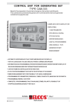
COMPLETE WITH DISPLAY TO
SHOW:
useful signals for
generator set management.
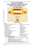
8 instruments:
- mains voltmeter
- generator voltmeter
- generator frequency meter
- total hour meter
- partial hour meter
- battery voltmeter
- fuel level indicator only for models
with fuel level sensor.
Threephase
INSTRUCTION AND USER MANUAL
32 ATS
Amp (Ac1)
SIMULTANEOUS READING
OF 6 INSTRUMENTS
TYPE
REMOTE SWITCHING MAINS/GENSET
SINGLE-PHASE VOLTMETRIC MAINS/GENERATOR CONTROL
AUTOMATIC BATTERY CHARGING (1A)
AUTOMATIC SUPERVISION OF FAULTS
GLOW PLUGS CONTROL
STARTER CONTROL
REMOTE COMMANDS WITH CONTACTS (STARTUP- STOP - TEST)
PROGRAMMING OF PARAMETERS MADE EASY BY DIP SWITCHES
AVAILABLE INPUT FOR ANOMALY
CLOCK FOR PROGRAMMING THE START UP OR STOPPING
OF THE GENSET
PROGRAMMABLE WEEKLY SELFTEST
ANOMALY HISTORICAL RECORD (Including data from the last 100 anomalies)
FUNCTIONS ON REQUEST
- KEY FOR EMERGENCY MANUAL STARTUP
- MAINS THREE-PHASE VOLTMETRIC CONTROL
- GENERATOR OVERLOAD SWITCH
- EMERGENCY BUTTON
- PRE-WIRED MALE CONNECTOR
GB 32 - 45 - 60 ATS
1
%5,(),16758&7,216
5(027(&21752/6 ,1',&$7,21
'(6&5,37,21
217+(',63/$<
STARTING
STOPPING
EJP STARTING
EJP SWITCHING
CONSENT
CALL FROM EXTERNAL VOLTMETRIC
RELAY
THE FUEL LEVEL
INDICATOR
IS DISPLAYED
START
STOP
EJP START
EJP
TOTAL HOUR METER
THE DISPLAY SHOWS
CLOCK FOR
PROGRAMMING THE
START UP OR
STOPPING
OF THE GENSET
THE ENGINE
COOLING
IS DISPLAYED
PARTIAL
HOUR METER.
SHOWS HOURS OF
OPERATION SINCE
THE LAST TIME
THE GENERATOR
SET WAS
SWITCHED ON.
PUSH BRIEFLY
TO SHOW THE
INSTRUMENTS,
HOLD DOWN TO
VERIFY THE LED
TEST OR THE
GENERAL ALARMS
SILENCING
AND TO VIEW
THE HISTORICAL
RECORD
BATTERY CHARGER
IN OPERATION
THE DISPLAY SHOWS:
• VOLTMETER
• MAINS/GENSET
AMMETER
AU T
OFF
MAN
T EST
S TA RT
K
V OL T
AMP
HZ
ST OP
K
MAINS
• GENSET
FREQUENCY- GENERATOR
METER
BATTERY
!
A1
AVAILABLE
FAULT
EMERGENCY
STOP
THE GLOW PLUGS
PREHEATING
IS DISPLAYED
STARTING
FAILURE
ALARM
THE DISPLAY SHOWS:
THE TOTAL OPERATING
HOURS AND THE G.S.
FREQUENCY
STOPPAGE DUE TO
OVERFREQUENCY
STOPPAGE DUE TO
ENGINE
OVERHEATING
THE GENERATOR IS
ON: LED ON
GENERATOR
UNDER-VOLTAGE:
FLASHING LED
(A FLASH THEN A
PAUSE)
GENERATOR
OVER-VOLTAGE:
FLASHING LED
(TWO FLASHES
THEN A PAUSE)
ALARM DUE TO
NO FUEL
STOPPAGE DUE TO:
• BELT BREAKAGE
• BATTERY
CHARGING FAILURE
STOPPAGE DUE TO:
• INSUFFICIENT OIL
PRESSURE
MAINS VOLTAGE
IS PRESENT
PRESS TO
SELECT THE
FUNCTIONS OF:
• AUT
• OFF
• MAN
• TEST
USER IS CONNECTED TO MAINS
PRESS TO RESET,
THIS OPERATION
ENABLES ALL THE
BLOCKED
FUNCTIONS
CUMULATIVE
ALARM
USER IS
CONNECTED TO
THE GENERATOR
KEY ENABLED WHEN THE
CONTROL PANEL IS IN
MANUAL OPERATION,
PRESS TO DIVERT THE
MAINS TO THE POWER
USERS, OR TO THE
GENERATOR WHEN THE
ENGINE IS RUNNING
PUSH TO START
THE ENGINE
WHEN THE
CONTROL PANEL
IS IN MANUAL
FUNCTION
ENGINE IS
RUNNING
PUSH TO STOP
THE ENGINE
WHEN THE
CONTROL PANEL
IS IN MANUAL
FUNCTION
,167580(176
2
• MAINS VOLTMETER
For single-phase voltage up to 254 V~, three-phase up to 440 V~
• GENERATOR VOLTMETER
For single-phase voltage up to 254 V~, three-phase up to 440 V~
• GENERATOR FREQUENCYMETER
From 0 Hz to 85 Hz for alternating voltages with amplitude
greater than 20 V~.
• TOTAL HOUR METER
With five figures and a maximum reading of 99999.
• PARTIAL HOUR METER
With four figures and a maximum reading of 9999. The minutes can
be read up to 99 hours
• BATTERY VOLTMETER
For voltages between 9 and 38 V= .
• FUEL LEVEL
INDICATOR
Displays the percentage of fuel present in the tank.
Only for models with fuel level sensor.
GB 32 - 45 - 60 ATS
127,&(6
:DUQLQJDGKHUHFORVHO\WRWKHIROORZLQJDGYLFHV
- Make sure that the mains and generator conductors are correctly connected
to the terminal board.
- Check that the absorption and consumption of the connected equipment are
compatible with the described technical characteristics.
- Install in such a way that there is always adequate heat disposal.
- Always install under other equipment which produces or spreads heat.
- The equipment must be earthed via the relevant terminal.
- Handle and connect without mechanically stressing the electronic card.
- Make sure that copper conductor cuttings or other waste material do not fall
inside the panel.
- If necessary, the fuses must only be replaced with the same type as the
original.
- Never use a battery charger for the emergency start-up; the electronic cards
could be damaged.
WARNING: The genset unit will restart automatically, when there is a mains failure or in
test mode, or with the remote controls.
To exclude the possibility of sudden or unwanted starts, switch to "OFF” using the
button
.
WARNING! Before performing any technical interventions on the genset unit, for the safety of
the operators, terminal "50" of the start motor (start command) must be disconnected, the
connections to the unit must be disconnected, the emergency stop button must be pressed
and the control panel locked to the “OFF” position.
ELECTROMAGNETIC COMPATIBILITY
This panel functions correctly only if inserted in plants which conform with the CE marking
standards; it meets the exemption requirements of the standard EN50082-2 but it cannot be
excluded that malfunctions could occur in extreme cases due to particular situations.
The installer has the task of checking that the disturbance levels are within the requirements of
the standards.
NOTE CONCERNING CONNECTION OF COMMAND AND SAFETY DEVICES TO THE
PANEL
With the direct connection of engine protection probes and remote control and command
contacts to the panel, particular anomalous situations (earth anomalies or interruption of
electrical connections) could block the start-up or provoke its early activation.
To reduce these risks, if he believes it to be necessary, the installer can take on the
responsibility of applying that which is described in paragraphs 9.4.2.1 and 9.4.2.2 of standard
CEI EN60204-1(CEI 44-5) to the said connections.
81/(66:(0$.($:5,77(1'(&/$5$7,2167$7,1*7+(&2175$5<7+,63$1(/,6
127 68,7$%/( )25 86( $6 $ &5,7,&$/ &20321(17 ,1 (48,30(17 25 3/$176
5(63216,%/()25.((3,1*3(562162527+(5/,9,1*%(,1*6$/,9(
Any use which differs from that which is indicated in this instruction and user manual must be
authorized by us.
GB 32 - 45 - 60 ATS
3
MAINS CONNECTION
The panel connection must be made with the MAINS DISENGAGED and the BATTERY DISCONNECTED, in
accordance with the scheme on pages 6-7.
Multi-polar cables with EPR (flame resistant) insulation and scratch proof PVC sleeves must be used, nominal
voltage 450/750V.
The panel must be connected to the existing earth unit, via a YELLOW/GREEN cable with cpn insulation and with
a minimum section of 16 mm².
The panel contains the protection devices of the engine-generator unit (see OPERATION at pages 8-9-10).
The client has the responsibility for installing, on the mains line, the protections against over-currents (fuses or
thermo-magnetic switches) and contact voltages (differential), limiting the presumed short circuit current to 10kA.
The electric cabinet has a space for the installation of a protection device against overload currents in the
generator set line.
The protections against direct/indirect contacts on the genset unit line, must adhere to the requirements
described in the regulation CEI 64-8.
GENERATOR
*6
MAINS
SWITCHING
PANEL
BEFORE SUPPLYING VOLTAGE:
- make sure that the live parts are inaccessible.
- check the earth connection.
kWh
PROTECTION
DEVICE
see CEI 64-8
Finally, check that the indicators, the block and
alarm devices and the remote switch function
correctly.
PROTECTION
DEVICE
see CEI 64-8
USER
WARNING
THIS ELECTRICAL PANEL IS NOT SUITABLE FOR USE WHERE THE FOLLOWING CONDITIONS
ARE PRESENT:
- temperatures, relative humidity values and altitudes which differ from those specified;
- in places where the temperature and pressure variations are so rapid that they produce exceptional
condensation inside the panel;
- in places where there are high levels of pollution due to dust, fumes, corrosive or radioactive particles, vapours
and salts;
- where there is exposure to high temperature due to solar radiation or furnaces;
- where attacks from mould or small animals are possible;
- in places where there is the risk of fires or explosions;
- subjection to strong vibrations or knocks;
- inside installations where the current throughput or interruption power could be influenced by certain conditions
(e.g equipment incorporated in machinery).
RUNNING AND MAINTENANCE
The following maintenance operations should be performed each week:
- automatic start with switching;
- check that indicators function;
- check batteries;
- check that conductors are tight and condition of terminals.
WARNING: DANGEROUS LIVE PARTS
Only assigned and suitably trained personnel are allowed to have access to the inside of the panel.
No operations inside the panel are permitted unless the plant has been disconnected from the mains and from the
genset unit.
The phases should be earthed and short-circuited as a safety measure.
Notwithstanding what is stated above, only assigned and trained personnel can have access to the inside equipment
when the plant is live, to perform the following operations:
- visual inspection of the equipment;
- visual inspection of the connections and the markings;
- measurement of voltage and/or current values.
These operations must, in any case, be performed using a tool which guarantees the appropriate electrical protection.
4
GB 32 - 45 - 60 ATS
&/2&.352*5$00,1*
TO PROGRAMME SELECT THE OFF FUNCTION
&/2&.$OORZVJHQHUDWRUVHWRSHUDWLRQRUVWRSSLQJWREHSURJUDPPHG
7,0(6(77,1*6ZLWFKLQJRIIWKHSRZHUVXSSO\WRWKHFRQWUROXQLWZLOO]HURWKHFORFN
H[DPSOH
Press to
display
• Increases
67$57
6723
• Decreases
Press to set the clock.
67$57,1*&216(172SHUDWLRQREWDLQHGDVGXULQJPDLQVIDLOXUH
21
10
Example: starts at 12:15 hrs
stops at 15:20 hrs
Move DIP
switch 10 to ON
21
10
STA RT
Move DIP
switch 10 to OFF
STA RT
STA RT
Press and
wait until
OK is written
Press to
display
• Increases
67$57
6723
• Decreases
Press when the number flashes
67236WRSVVWDUWLQJRUUXQQLQJRIJHQHUDWRUVHW
21
10
Move DIP
switch 10 to ON
Example: stays locked
from 23:00 hrs
unlocked
at 07:30 hrs
ST OP
21
10
Move DIP
switch 10 to OFF
ST OP
Press and
wait until
OK is written
Press to
display
• Increases
67$57
6723
• Decreases
Press, when the number flashes
GB 32 - 45 - 60 ATS
5
:,5,1*',$*5$0
727+(7+5((3+$6(*(16(781,7&21752/3$1(/
Having made the connections, the control panel is enabled for manual operation.
To select other operating modes, see page 8
',(6(/(1*,1(
PERMANENT
MAGNETS
ALTERNATOR
85
85
30
30
STARTING
RELAY
86
TO 30 OF
START MOTOR
STOP
RELAY
87
86
YELLOW
RED
YELLOW
We reserve the right to change the charectistics at any moment and without warning.
FOR PETROL ENGINES
ASK FOR RELATIVE DIAGRAM
87
50
30
85
GRGB L C
30
+
GLOW
PLUGS
RELAY
86
R
87
+LE
FUEL
FLOAT
OVERHEATING
THERMOSTATIC
GLOW PLUGS
D+
W
B+
TO 30 OF
START MOTOR
PRE-EXCITATION
ALTERNATOR
OIL
PRESSURE
SWITCH
1.5mm
MIN.
5m
MAX
Connect the jumper
5E-6E if the emergency
button is not fitted
1
11
2
3
4
1
11
2
3
4
J
3
- LQ
WU
(
U DW
2V
CONNECT DIRECTLY
TO THE (-) TERMINAL
OF THE BATTERY
J
LQ
K
FLW
Z
V W
Q
3
- HV
(
U Q
2R
F
6
7
8
13
5
14
10
6
7
8
13
5
14
10
NEVER INSTALL THE EMERGENCY
PUSH-BUTTON LINKED TO A STOP
SYSTEM WHICH IS NOT ENERGIZED
WHEN THE UNIT IS RUNNING
IN THE PRESENCE OF
THE PRE-EXCITATION
ALTERNATOR, MOVE
THE BRIDGE
TOWARDS JP1.
DO NOT MOVE FOR
OTHER TYPES OF
ALTERNATOR.
0$,16'(7(&7,21
JP2
INTERNAL
GENERAL
ALARM
JP1
To check whether the engine
is running, simply connect
this terminal.
!
S
WR
6
Fuel level float level programmed
[*] with variable resistance
indicator
GROUND OF THE FUEL
LEVEL INDICATOR
CALL
()
WV
WH
UR
J
Q
WLU
WD
6
AVAILABLE
PROTECTION INPUT
6833/<
ENABLED WITH ENGINE
STARTING OR RUNNING
DISABLED WITH ENGINE
STATIONARY
+
STOP
()
STARTING
FU2
3,15A
GLOW PLUGS
PREHEATING
(0(5*
6723
ENGINE
RUNNING
DETECTION
EXTERNAL
OUTPUTS (+)
MAX LOAD OUTPUTS (+)
6 - 17
1A
15 - 19 - 70 3W
21
2))
YOUR ELECTRICAL TECHNICIAN CAN ASK US ANYTHING ABOUT
THIS PRODUCT BY TELEPHONING ONE OF OUR TECHNICIANS
6
GB 32 - 45 - 60 ATS
400V
5(027(&21752/6
(50m max)
1
,2
6
AUTOMATIC STARTS
5
(
EXCLUSION
9
1 672367+(67$5725027,212)7+(
2 < *(16(781,721/<,1$8720$7,&
/
10
02'(,1',&$7('%<7+(6,*1$/
2(
/
6723
1
1
6723,PPHGLDWH
:
:
)RU
VWRSZLWKRXWZHHNO\
9
VHOIWHVWIDFWRU\VHWWLQJ
9
SURJUDP
8 8
PLQJ
6 7(67(QJLQHFRROLQJ VHH
' 5 EHIRUHVWRSSLQJZLWKWKH
MRLQW$
$ DWSDJH
2 SRVVLELOLW\RIDZHHNO\
%
/ VHOIWHVW
$ 1
, 0 5 33
(
7 SINGLE-PHASE
230V VERSION
U1
8
V1 X-MAINS
W1
1
N1
B.M.
SINGLE-PHASE
230V VERSION
L1 L2 L3 L4
U3
8
V3 X-GENERATOR
W3
1
N3
U2
V2
X-USER
W2
N2
SINGLE-PHASE
230V VERSION
L1 L2 L3 L4 (7L4)
KM-R
KM-G
T1 T2 T3 T4
T1 T2 T3 T4
8
1
&$//
SINGLE-PHASE 230 V VERSION
DASHED CONNECTION
Kit of jumpers for LEM –435/32
FU 5
10A
NG
U4 N4
A1
+HDWHU9
30
KM-G
&211(&725215(48(67
16 POLES SOCKET
1÷16+
PLUG
N°
CABLE
TERMINAL LENGTH mt.5
88B
NR
A2
A1
1(01)
KM-R
KM-R
A2
84A
89
2(02)
90
FU4
10A
)81&7,216$6,)7+(5(,6$0$,16
)$,/85(
67$57,1*
1(01)
(Shown by the START on the display)
KM-G
88
86
80
81
2(02)
FU1
3,15A
FU3
3,15A
MAINS
CONTACTOR
CONTROL
TRC
BATTERY
CHARGER
MAINS
VOLTMETRIC RELAY
&$5'7<3(6($
352*5$00,1*
It is possible to change the
control panel functioning, using
the DIP-switch programmer
of the card.
21
2
1
1 2 3 4 5 6 7 8 9
GENERATOR
INPUT
VHFRQGDIWHUWKHFRQWDFWFORVHV
WKHJHQHUDODODUPFRPHVRQ
LQWHUPLWWHQWO\IRUVHFRQGV
DIWHUDVHFRQGSDXVHWKHVWDUW
F\FOHEHJLQVZLWKRSHUDWLRQWKH
VDPHDVWKDWZKHQWKHUHLVQR
PDLQV
32
GENERATOR
CONTACTOR
CONTROL
(1*,1(5811,1*
7+5(6+2/'$'-8670(17
Adjustment is not normally necessary.
If it is necessary, perform the following
operations:
- Start the engine manually and bring it
down to minimum speed.
3
- Turn the potentiometer
anticlockwise until
the indicator
lights up.
7(67
(Shown by the flashing
warning TEST ).
7KHVWDUWFRQWUROFDQEHFKDQJHG
XVLQJWKH7(67FRQWUROIRURSHUDWLQJ
LQVWUXFWLRQVUHIHUWR7(67RQSDJH
)RUSURJUDPPLQJVHHDWWDFKPHQW$RQ
SDJH
)257+()81&7,216215(48(67
.(<3(5(0(5*(1&<67$57,1*
7+5((3+$6(92/70(75,&&21752/
$6.)255(/$7,9(',$*5$0
CONSULT STANDARDS CEI 44-5 (EN60204) FOR INFORMATION CONCERNING PROTECTION
AGAINST OVERLOAD CURRENTS IN THE ELECTRICAL EQUIPMENT USING BATTERY VOLTAGE
GB 32 - 45 - 60 ATS
7
23(5$7,21
2))
)81&7,2166(/(&7,21
The function selected
using the button is
shown on the display.
0$1
7(67
$87
0$18$/
The control panel commands are enabled.
Starting with key
stopping with key
67$57
6723
CONTROL FOR MAINS-GENERATOR CONTACTORS
It is left to the key
By pressing on the key, the load is switched from the mains to the generator and vice versa.
PROTECTIONS
The generator set protection function in manual mode can be programmed in two ways:
· Display only of the fault that has intervened WITHOUT STOPPING the engine. The generator overfrequency
fault is programmed with stopping of the engine. It cannot be programmed without stopping of the engine.
· Display of the fault that has intervened WITH ENGINE STOPPING. (The control panel is programmed in this way).
$8720$7,&
When a fault occurs on the mains, (detected by the internal voltmetric relay, or by the external call), once the
2 seconds have elapsed, the control unit commands the opening of the mains contactor control, and starts the
generator set. With engine running and generator voltage normal and once the GENERATOR TO POWER
USERS CONNECTION DELAY has elapsed (programmed to 7 sec.) the generator contactor closes. While it is
running the generator set is protected from possible faults. When the mains voltage is restored and the MAINS
ACCEPTANCE time has elapsed (programmed to 40 sec.), the mains contactor closes (after the
GENERATOR-MAINS INTERLOCK time, programmed to 1,5 sec. not adjustable).
The COOLING TIME (programmed to 120 sec.) then allows the engine to be cooled easily before it is stopped.
7(67
7(67 , we obtain the engine startup cycle as in automatic,
up the lighting
On pressing key
and the power users remain supplied by the mains. If a mains fault occurs during the test, the power unit remains
in test mode, positions itself as in automatic operation and commands the closing of the generator contactor.
:((./<6(/)7(67
$87
7(67
ENABLED WITH POWER UNIT IN AUTOMATIC OR TEST MODE is indicated by the display
If the relative switch is positioned on TEST ENGAGED the general alarm is activated intermittently (for 8 sec.).
When the general alarm is deactivated, and after a pause of 3 seconds, the engine starts and continues to run for
3 minutes.
This test will be repeated automatically every week on the exact day and at the hour to which the
TEST ENGAGED switch has been positioned.
STOPPING OF ENGINE DURING THE TEST
Press button
and move to function
OFF
.
UPDATING OF THE HOUR LEAVING THE SWITCH ON TEST ENGAGED
and
Keep pressed at the same time keys
until the icon TEST
flash .
Press key
within 3 sec.
67$57
7(67
starts to
The weekly test cycle is therefore obtained as if the relative switch had been repositioned.
8
GB 32 - 45 - 60 ATS
23(5$7,21
2))
2))
Press button
until the warning led
comes on.
The engine cannot be started in any way and, if running the engine is stopped without carrying out engine
cooling. The mains contactor stays closed. The LEDs and the instruments are active.
*/2:3/8*635(+($7,1*
67$57
- In manual with key
that should be kept pressed until the engine has started.
- In automatic, Test and remote control, this is activated automatically before starting.
The preheating action ceases during the starting pulse.
67$57(5
- If programmed for the STARTER, the function is enabled at every odd starter pulse and is de-energised with
the engine runningo.
67$57
67$57,1*
- In manual mode with button
, in Test and with the remote control, it comes on immediately after the
GLOW PLUG CONNECTION TIME.
- In automatic mode or if a mains anomaly is detected by the internal voltmetric relay, or an external call, and after the
GLOW PLUG CONNECTION time (set to 2 secs; this time is always active, even in systems without glow plugs). To
facilitate starting a given circuit leads to a succession of starts: 4 if set for diesel motors, each of 5 seconds
with pauses at intervals also of 5 seconds. Otherwise, 15 pulses of 3 seconds each, each with pauses of 5 seconds
if set for petrol motors.
67$57,1*)$,/85(
Blocks the start cycle if the motor is not started after the whole succession of pulses.
This is shown by a special symbol
.
6723
0DQXDO mode using key 6723 .
- In 7HVW mode when the protection systems or the remote controls intervene.
- In $XWRPDWLF mode when the mains power returns, or when the protection systems or remote controls intervene.
- In
Stopping for the Diesel engines can occur in two ways:
• With the solenoid deactivated while the engine is running and activated when stopped. This condition is
maintained during the STOP TIME (programmed to 20 seconds) after the engine stopped detection.
• With solenoid or electro-valve activated while the engine is running and deactivated when stopped, remaining in
this condition even when the engine is stationary.
- In PETROL engines, removing the supply from the start system.
'(7(&7,21(1*,1(5811,1*
This is obtained with detection (adjustable P1) of the voltage and frequency of the battery charger alternator
(PERMANENT MAGNETS or PRE-EXCITATION) and from the frequency and residual voltage of the generator.
When detection has been made, it disconnects the starter motor and lights the LED
.
.
3527(&7,216
Memorized with engine stop, they can be divided into three groups:
- always active, for the faults generator undervoltage or overvoltage (indicated by the flashing signal)
(stopping without engine cooling).
- active when engine is running, for OVERHEATING
and OVERAFREQUENCY ANOMALY
stopping without engine cooling.
- active 10 seconds after the engine running detection for the following anomalies:
INSUFFICIENT OIL PRESSURE
and FAULT AT THE BATTERY RECHARGING ALTERNATOR
(belt breakage) and A1.
$/$50
Always active, memorised, stops the motor as a result of the fuel empty anomaly
.
5(6(7
By pressing the key
GB 32 - 45 - 60 ATS
, the protection devices and all the stopped functions are re-activated.
9
0$,1$/$50
This can be obtained by mounting an indicator connected to the relevant output.
It is activated continuously.
When key
is pressed, the main alarm is silenced.
It is activated intermittently for 8 seconds, followed by a pause, before beginning the generator set remote
start up.
5(027(&21752/6
67$57257(676723(0(5*(1&<
(-3)81&7,21
Enabled with control panel in automatic and programmed with switch 10 (see programming joint A page 4).
When the START UP contact closes (terminal 32), EJP START is seen on the display. After the EJP STARTUP
DELAY time (programmed to 25 min.) has elapsed , the start up procedure begins.
When the switching contact (terminal 33) closes,
EJP is seen on the display and the operation is as when
there is a mains fault.
When the two EJP contacts are opened functioning is as when the mains power returns.
(0(5*(1&<6723
The emergency stop can be activated in all working conditions, by mounting one or more click down push-button.
The stop is immediate (without engine cooling), enables the general alarm and ! is shown on the display.
Do not use the emergency push-button linked to a stop system that is not energized when the unit is
running.
$8720$7,&%$77(5<&+$5*(5
FIXED LIGHT
- Rapid charge via current control
- Intermediate and maintenance charge via voltage control
23(5$7,21
Automatic charging takes place at three levels:
- Rapid charging via current control 1,5A until 13,2V (26,4V) are reached in the battery.
- Intermediate charge via voltage control, until13,5 V (27V) are reached in the battery.
- Maintenance charge using a very low current value, but sufficient to maintain the voltage value at 13,5 (27 V).
The GREEN LED is lit only when the following conditions happen at the same time:
- mains on;
- battery voltage above the 65% (+/- 10%) of the rated value.
3$57,$/+2850(7(5
Press
to select
the operating hours and minutes of the last run of the genset unit.
The hours indicated are zero-set the next time the genset unit is started up.
10
GB 32 - 45 - 60 ATS
&20321(176/,67
'(6&5,37,21
7<3(
SEA-430 12 V
24 V
VA 15 12V
VA 24 24V
PS 10/E 50.101.001
10A
ELECTRONIC CARD
TRANSFORMER
FUSES HOLDERS
FUSES
CBD10
TERMINAL BOARDS
CBD16
CL02A400T6
VERSION 32 ATS
CL03A400M6
VERSION 45 ATS
CL0400M6
VERSION 60 ATS
CONTACTORS COUPLE
HORIZONTAL MECHANICAL
INTERLOCK
(/&26
0$18)$&785(5
48$17,7<
ELCOS
1
S.EL.IT.
1
WIMEX
2
CABUR
4
16
24.22.45
24.22.46
51.22.18
51.22.19
45.08.33
40.03.06
42.17.86
42.17.90
10.01.12
1
10.01.13
10.01.15
G.E.
10.01.51
BELA 02
DIMENSIONS
1
TECHNICAL DATA
PANEL CONFORMING WITH STANDARDS
CEI 17-13/1 (EN60439-1) CEI 44-5 (EN 602041-1)
TYPE
32 ATS
304
284
255
200
8,5
CONTACTOR
CAPACITY
(AC1)
32 A
THREE-PHASE
58 A
SINGLE-PHASE
CONTACTORS
SHORT DURATION
CURRENT
570 A x 1
45 ATS
45 A
1010 A x 1
60 ATS
60 A
1010 A x 1
377
400
420
316
- Rated mains/generator voltage
- Battery supply voltage
-
184
255
-
400 VAC
12VDC (16VDC MAX)
or 24VDC (32VDC MAX)
Frequency
50÷60 Hz
Absorption with engine running without mains
150 mA at 12V 90 mA at 24V
Selfabsorption with engine stationary without mains 38 mA at 12V 25 mA at 24V
Battery charger supply
MAX 1 A
Heater output
230 VAC MAX 1500 W
Rated insulation voltage:
- Mains voltage terminals
400V
- Battery voltage terminals
32V
Insulation class
Class I
Hour meter
4 digits
Frequency meter
0-85 Hz, Precision ±0,1 Hz
Battery voltmeter
Max 38V, Precision 2%
Mains voltmeter
Max 440V, Precision ±2%
Generator Voltmeter
Max 440V, Precision ±2%
Generator ammeter (on request)
Max 60A, Precision ±2%
Outputs 6-17
MAX 1A
Outputs 15 - 19 - 70
MAX 3W
Degree of protection:
Accessible sides
IP40
Wall sides
IP20
Temperature range
-30 ÷ +40 º C
Relative humidity
90% MAX (without condensation of water) at 40°C
Altitude
MAX 1000 mt a.s.l.
Functioning of system
in insulation
Installation conditions
for internal use
Plant system to which it is connected
TN-IT-TT
Panel weight:
- VERSION 32 ATS
Kg. 7,2
- VERSION 45 ATS
Kg. 7,6
- VERSION 60 ATS
Kg .8,2
The protections against direct/indirect contacts on the genset unit line, must
adhere to the requirements described in the regulation CEI 64-8
GB 32 - 45 - 60 ATS
11
ORDERING DATA
Type
32 ATS
32 ATS
45 ATS
45 ATS
60 ATS
60 ATS
Volt
12
24
12
24
12
24
Code
02.14.97
02.14.98
02.14.93
02.14.94
02.14.95
02.14.96
SUPPLIED ACCESSORIES
MOUNTING BRACKET KIT
KIT OF JUMPERS
12
75.06.89
75.06.89
17.99.11
GB 32 - 45 - 60 ATS