1
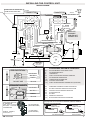
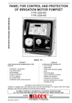
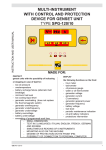
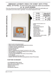
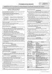
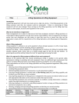
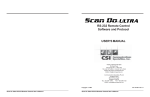
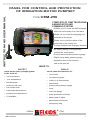
INSTRUCTION AND USER MANUAL
PANEL FOR CONTROL AND PROTECTION
OF IRRIGATION MOTOR PUMPSET
TYPE
CEM-256
COMPLETE OF GSM TELEPHONE
ANNUNCIATOR AND
COMMAND SYSTEM
• Notifies up to 3 users via SMS message
when the motor pump is on the alarm
• Allows you to control the stopping and
restarting of the pump
• Allows you to view the status of the
main tools of the control unit
• Comes complete with high-gain antenna
• By simply starting, it automatically
controls the motor pump
• Pump water electronic pressure gauge
• Digital pump water pressure gauge
• Assembly also on the machine
and in the open air.
MADE TO:
PROTECT
motor pump sets by stopping them
in the event of:
•
low oil pressure
•
over-temperature
• belt breakage
• minimum fuel level
• low coolant level
• low pump water pressure
• pump water overpressure
DISPLAY
on the panel the functions of:
•
hour-meter
•
oil pressure gauge
•
water or oil thermometer
•
tachometer
•
pump water pressure gauge
•
timer
•
fuel level gauge
• pump protection exclusion
• A1 available
• battery and oil lights
• protections intervention
• emergency stop
PARMA
GB CEM-256/3
® ITALY
Tel. +39 0521/772021 Fax +39 0521/270218
E-mail: [email protected] - HTTP://www.elcos.it
1
BRIEF INSTRUCTIONS
After starting, the motor pump protects itself automatically
PUMP WATER
BAR
PRESSURE IS DISPLAYED
MOTOR PUMP OPERATING
SPEED IS DISPLAYED
ENGINE OIL PRESSURE
IS DISPLAYED
ENGINE WATER OR OIL
TEMPERATURE IS DISPLAYED
FIELD SIGNAL STRENGTH
SMS MESSAGE BEING
RECEIVED OR SENT
A1 AVAILABLE
SYSTEM ERROR.
MISSING SIMCARD.
PROCEDURES FOR DISABLING
THE PIN CODE, NOT REGULAR
CUMULATIVE ALARM
THE FUEL LEVEL
IS DISPLAYED
ACCUMULATED
OPERATION HOURS
ARE DISPLAYED
PRESS IF YOU WANT
TO SET WORKING
TIME ( UP TO 24
HOURS)
PRESS TO SELECT THE
DISPLAYED FUNCTION,
EACH TIME IT IS
PRESSED, THE INSTRUMENT INDICATED BY THE
DISPLAY CHANGES.
%
STOP
BAR
°C ~
~
STOP
EMERGENCY STOP
PRESS UNTIL THE 2
SIGNS START FLASHING
TO EXCLUDE PUMP
PROTECTION.
TO RE-ACTIVATE
PROTECTION, PRESS
AGAIN UNTIL THEY
SWITCH OFF.
h
STARTUP FAILURE
ALARM
PRESS TO ADJUST
WATER PUMP
ELECTRONIC
PRESSURE SWITCH
WATER PRESSURE IS
REGULAR
~
~
RPM
!
A1
~
~
BAR
~
~
CELL
~
~
NO_CELL
~
~
M
P
PUMP PROTECTION
IS ACTIVE
THE BATTERY IS
NOT CHARGING
LOW ENGINE
OIL PRESSURE
ENGINE
PROTECTIONS
ARE ACTIVE
0
AUT.
AVV.
®
www.elcos.it
STOPPAGE DUE TO LOW
FUEL LEVEL
STOPPAGE DUE TO INSUFFICIENT
ENGINE OIL PRESSURE
STOPPAGE DUE TO LOW
COOLANT LEVEL
STOPPAGE DUE TO LACK OF BATTERY
CHARGING (BELT BREAKAGE)
STOPPAGE DUE TO HIGH
ENGINE TEMPERATURE
~
~
STOPPAGE
DUE TO LOW
PRESSURE
OR
PUMP WATER
OVERPRESSURE
OR
ELECTRONIC
PRESSURE GAUGE
(TRANSMITTER)
INTERRUPTED.
IN THIS CASE,
THE ANOMALY IS
HIGHLIGHTED BY
THE FLASHING
WARNING LIGHT.
~
~
LOW PRESS.
OVERPRESS.
DISCONN'ED
START KEY
0
AUT.
AVV.
- OFF
- STOPPAGE IN ALL OPERATING CONDITIONS
- RESTORE PROTECTIONS, CANCEL PUMP PROTECTION EXCLUSION AND TIMER,
DEACTIVATE INSTRUMENTS.
- CONTROL PANEL SUPPLY
- TURNS ALL THE LIGHTS ON FOR 2 SECONDS ( EFFICIENCY
CHECK )
- PRESSURE SWITCH ADJUSTING (SEE PAGE 3)
- MOTOR PUMP START UP
2
GB CEM-256/3
ADJUSTING THE PUMP WATER ELECTRONIC PRESSURE GAUGE (TRANSMITTER)
It controls the pressure of the system, replacing the conventional pressure switch.
PUMP PROTECTION
No adjusting is required
P
The protection of the pump is enabled when the PUMP PROTECTION ACTIVE
information comes on, after the water
pressure has been steady for 2 consecutive minutes and in any case after 10 minutes from starting of the engine.
Intervention of the protection occurs 5 seconds after the pressure goes up or down by two bars, stops the engine and is shown on
the display:
It is possibile to change the two bars of the pressure
lowering (low pressure) by using the key
BAR
This change is cancelled when
the engine stops.
OVERPRESS.
Pump water
overpressure
or
INSUFF.
PRESS.
LOW PRESS.
Low
pressure
(low pressure)
OVERPRESSURE remains set to two bars, this value is
added to the working pressure (for example, working
pressure 9 bar overpressure 11 bar)
WORKING PRESSURE
Press to adjust
the value of
low pressure
(PRESSOSTAT)
BAR
BAR
PRESSOSTAT
BAR 7
Press to
select the
pump water
pressure gauge
TIMER
Enabled with key on “AUT”, it makes it possible, if necessary, to have the motor pump work for an adjustable length of time (24 hours maximum),
at the end of which it stops and the WORK TIME OVER
sign lights up on the display.
STOP
The work time is set by pressing the push-button
DISPLAY
.
(
lights up) until the desired value appears on the
On releasing the push-button, the timer automatically starts working, continously displaying the remaining work time.
CANCELLING THE SET TIME
To zeroing the set time there are two methods:
- keep the push-button
pressed until it reaches zero.
- by turning the starter key onto "ZERO" (the engine pump will stop).
PUMP PROTECTION EXCLUSION
(ENABLED ONLY WITH ENGINE RUNNING)
The push-button
excludes pump protection:
- exclusion is obtained by keeping it pressed for at least 3 consecutive seconds; the function is indicated by the two intermittent lights
.
- this exclusion is cancelled by pressing the push-button again, or by turning the start key onto "ZERO".
OIL AND BATTERY INDICATOR LIGHTS
Lit up with key on "AUT", they switch off with the engine running and regular oil pressure and battery charge system.
ENGINE PROTECTIONS
The engine protections are enabled when the ENGINE PROTECTIONS ACTIVE light M
comes on (20 seconds after the end of starting impulse
and however 1 minute after positioning the key on “AUT”).
Interventions of the protection probes (fitted on the engine), indicated by the relevant lights, stop the engine, they are memorised and can be split into
two groups.
Delayed by 2 seconds for:
- OIL PRESSURE SWITCH
- OVERTEMPERATURE
SWITCH
~
~
~
~
Delayed by 5 seconds for:
- A1
- BATTERY CHARGE ALTERNATOR
(ALTERNATOR BELT BREAKAGE)
- FUEL LEVEL SWITCH
- Fuel reserve flashing signal: 20% fuel reserve
(T) (WITHOUT ENGINE STOP)
- Signal always on: stop for minimum fuel level (W)
- PROBE FOR COOLANT LEVEL
GB CEM-256/3
3
INSTALLING THE CONTROL UNIT
COOLANT LEVEL PROBE
FOR RADIATORS WITH
PLASTIC EXPANSION TANK
FOR RADIATORS WITH
METAL EXPANSION TANK
WARNING
!
IF THE FUNCTION
- LOW COOLING
LIQUID LEVEL
IS NOT USED:
CONNECT YELLOW/
ORANGE WIRE
TO EARTH
155
155
SCREW
ELECTRODES
ROD
ELECTRODE
YELLOW/
ORANGE
TO REPLACE THE FUSES
AND INSERT THE SIM CARD,
REMOVE THE COVER
FROM THE CONTROL UNIT
1/4”
GAS
3/8”
GAS
PUMP WATER PRESSURE TRANSMITTER CABLE
The control unit has been
designed to control
stopping with an
ELECTROMAGNET
N
ROW
E/B
BLU
BL
To view the water/oil THERMOMETER and the oil pressure GAUGE,
connect the transmitters to the respective wires of the unit,
then CUT and isolate the BLACK/VIOLET wire
AC
K
/VIOL
SET UP
• WATER OR OIL
THERMOMETER
• OIL PRESSURE GAUGE
STOP SYSTEM SET UP
To stop with the SOLENOID VALVE
cut and isolate the BLUE/BROWN lead
ET
EXCITED WHILE RUNNING
(with EMERGENCY
button)
WHITEORANGE
EXCITED WHILE
RUNNING
YELLOW
YELLOW
STOP SYSTEMS
85 30
86
WHEN THE
EMERGENCY
BUTTON IS
MOUNTED
REMOVE
THE WHITEORANGE
BRIDGE
(LOCATED
INSIDE
THE PANEL)
EMERGENCY
BUTTON
87
SOLENOID
to close
the fuel
SOLENOID
to close
the fuel
7
85
86
30
4 20
EXCITED IN STOP MODE
YELLOW
WARNING! :
IT IS NOT
POSSIBLE
TO MOUNT
THE
EMERGENCY
STOP BUTTON
ON A STOP
SYSTEM WITH
ELECTROMAGNETS
87
85
86
30
87
2
ELECTROMAGNET
to activate the
engine stop lever
TACHOMETER ADJUSTMENT
Run the engine at
a costant and
known rpm
value
(for example by
means of
a portable
revolution counter)
RPM
Select the instrument
TACHOMETER,
keep the button
depressed for at
least 5 seconds and simultaneously press
BAR
increase
or
decrease
until the correct reading appears on the display.
Release the buttons and wait until OK appears on the display.
4
GB CEM-256/3
INSTALLING THE CONTROL UNIT
WIRING DIAGRAM
FROM 15/54 OF START KEY,
USABLE FOR AUXILIARY
3A MAX
157
CONNECTOR
CONNECTOR
3A MAX
RED/GREEN
YELLOW/ORANGE
11
6
5
4
3
2
1
GREY
WHITE/RED
GREEN
155
26/28
A1
191
SKY/BLUE
6
5
4
3
2
1
CABLE 2,5m
7
ORANGE/
BLUE
T INDICATOR
W RESERVE
4
112
WHITE/GREEN
40A MAX
BLACK
30
RED
INSULATE
POSSIBLE
CABLES NOT
CONNECTED
ORANGE
8
BROWN (ONLY FOR PERMANENT MAG.)
WHITE
YELLOW
9
ORANGE/BROWN
WHITE/VIOLET
10
18
173
50
+ BATTERY
3A MAX
97
2/7
40
3
41
STOP
SYSTEMS
SEE PAGE 4
CHARGE BATTERY ALTERNATOR:
PRE-EXCITATION
WHITE/RED
+ BATTERY
GREEN
W
B+
D+
28
DO NOT USE
BROWN
PERMANENT MAGNETS
WHITE/RED
YELLOW
RED
YELLOW
+ BATTERY
R
26
+ LE
GREEN
27
GRGB L C
+
BROWN
27
CONNECTION SYSTEM
FOR EXTRACTING THE
W TERMINAL IN
P R E - E X C I TAT I O N
B AT T E RY C H A R G E
ALTERNATORS.
(BOSCH, MARELLI,
LUCAS, ECC...)
GB CEM-256/3
ACCESSORIES AVAILABLE ON REQUEST
(2/7)
ELECTROMAGNET OR SOLENOID VALVE
(3)
OIL PRESSURE SWITCH
(4)
(18)
THERMOSTAT
FUEL FLOAT FOR INDICATOR AND RESERVE
(97)
(112)
OIL PRESSURE TRANSMITTER
TEMPERATURE TRANSMITTER
(155)
COOLANT LEVEL PROBE
(173)
PUMP WATER PRESSURE TRANSMITTER (SUPPLIED)
(26)
PERMANENT MAGNETS CHARGE ALTERNATOR
(27)
BATTERY CHARGE ALTERNATOR REGULATOR
(28)
PRE-EXCITATION CHARGE ALTERNATOR
(40)
STARTING MOTOR
(41)
BATTERY
(157)
GENERALALARM LIGHT
(191)
A1 AVAILABLE FOR PROTECTION PROBE
SELECT LANGUAGE The language set up is ITALIAN; the
languages that can be selected are: ENGLISH, FRENCH, GERMAN,
SPANISH and PORTUGUESE.
TO TACHOMETER
(WHITE/RED WIRE)
ON
1
}
To diode bridge
(inside alternator)
Move DIP
switch 1 to ON
ITALIANO
Press to select
the desired language
ON
1
Move DIP
switch 1 to OFF
ENGLISH
Press and wait for
OK to be written
5
OPERATION
CONTROLLING THE CONNECTION OF THE PUMP WATER
ELECTRONIC PRESSURE GAUGE (Transmitter)
Turning the key to the AUT position stops the electronic pressure gauge.
Control is activated 1 minute after the completion of the starting pulse.
Intervention is highlighted by the relevant indicators
and stops the motor pump after 2 seconds.
To exclude intervention, press the push-button
DISCONN'ED
flashing warning light
PUMP PROTECTION EXCLUSION.
PUMP PROTECTION
The pump protection is enabled with the switching on of the ACTIVE PUMP PROTECTION (after 2
minutes of stable water pressure, indicated by the visual signal REGULAR PUMP PRESSURE
case, 10 minutes after the start of the motor pump)
consecutive
and, in any
The intervention of the protection (5 seconds after the increase or decrease of the pressure) stops the engine and
is indicated by the visual signal for
LOW PUMP WATER PRESSURE or
WATER PUMP OVERPRESSURE
.
RESET : is obtained by turning the start key onto "ZERO".
STOPPING THE MOTOR PUMP
The control unit shuts down the engine in five conditions:
- turning the starter key onto "ZERO”
- protection intervention
- timer intervention at the end of the work period
- giving the command from a cell phone
- through intervention of the external emergency.
The unit adapts to two different stop systems
- by working the ELECTROMAGNET for 20 seconds which pulls the STOP lever
- by cutting off power to the SOLENOID VALVE shutting off the flow of fuel.
ANOMALY REPORT
HISTORICAL appears on the display.
Simultaneously press four buttons (for at least 5 seconds): the word
Release the buttons, and for 10 seconds the display will show the most recent anomaly that caused the pump to stop.
AUTOMATIC RESTART WITH CELL PHONE
It is not possible to restart the motor pump with the key in the 'zero' position.
Restarting is possible after the pump has been stopped by cell phone or timer.
Before the start, the internal annunciator sounds for 8 seconds, and, after a 3 second pause, startup begins. To
facilitate startup, a special circuit emits a series of four, 5-second pulses, with a 5-second delay between each pulse.
START UP FAILURE
Blocks the startup cycle if the pump has not started up after the fourth pulse.
GENERAL ALARM
This can be obtained by fitting on the outside an optical and/or acoustic signaller to be connected to the RED/GREEN
wire. It is activated on protection intervention.
EMERGENCY STOP
It can be obtained in all functioning conditions, mounting one or more release-type buttons. It is indicated by the
!
visual signal
and enables the general alarm.
INSTRUMENT SELECTION
The control unit comprises six instruments:
HOUR METER - Total hours of operation (with the engine running the signal
pulsates, to
h
indicate the correct functioning of the HOUR-METER).
INSTRUMENTS WHICH CAN BE SELECTED IN SEQUENCE BY PRESSING THE BUTTON
Each time it is pressed, IT SHOWS the next instrument. WHEN THE TIMER IS set, the duration of the display of
the instrument is limited to 30 seconds from the activating of the button; the TIMER then reappears.
bar
C
RMP
BAR
%
6
- PRESSURE GAUGE - Engine oil pressure
- THERMOMETER - Engine oil and water temperature
- TACHOMETER - Speed of motor pump
- PRESSURE GAUGE - Pump water pressure
- INDICATOR - Fuel level percentage
FITTED ON ENGINE
} TRANSMITTERS
ON REQUEST
GB CEM-256/3
®
S.r.l.
Via Naviglio Alto, 24/a-43100 PARMA ITALIA
Tel. +39 0521/772021
Fax +39 0521/270218
E-mail: [email protected]
HTTP://www.elcos.it
CONTROL AND PROTECTION UNIT
FOR IRRIGATION ENGINE PUMP
TYPE CEM-256
Only for starting and surveillance of the diesel motor pump and stops it if there are anomalies in
the parts controlled by probes.
It has been designed to be installed also on the machine.
NOTICES
!
Warning:
adhere closely to the following advice
- Always install under other equipment which produces or spreads heat.
- Always follow the Wiring Diagram on pages 4-5 when making connections.
- Check that the line loading and the consumption of the connected equipment are compatible
with the technical characteristics on page 8.
- All technical interventions must be performed with the engine stationary and terminal 50 of
the starter motor disconnected.
- Never use a battery charger for the emergency start-up, this could damage the control unit.
- To protect the safety of persons and the equipment, before connecting an external battery
charger, disconnect the electrical plant terminals from the battery poles.
- Never disconnect the battery terminals with the engine running.
THIS CONTROL UNIT IS NOT SUITABLE FOR OPERATING IN THE FOLLOWING
CONDITIONS:
- Where the environmental temperature is outside the limits indicated in the Technical Data on
page 8.
- Where there are high levels or heat from radiation caused by the sun, ovens or the like.
- Where there is the risk of fire or explosions.
- Where the panel can receive strong vibrations or knocks.
ELECTROMAGNETIC COMPATIBILITY
This control unit functions correctly only if inserted in plants which conform with the CE marking
standards; it meets the exemption requirements of the standard EN61326-1 but it cannot be
excluded that malfunctions could occur in extreme cases due to particular situations.
The installer has the task of checking that the disturbance levels are within the requirements of
the standards.
CONDUCTION AND MAINTENANCE
The following maintenance operations should be performed every week:
- check that the indicators function;
- check the batteries;
- check that the conductors are tight, check the condition of the terminals.
UNLESS WE MAKE A WRITTEN DECLARATION STATING THE CONTRARY, THIS CONTROL UNIT IS NOT SUITABLE FOR
USE AS A CRITICAL COMPONENT IN EQUIPMENT OR PLANTS RESPONSIBLE FOR KEEPING PERSONS OR OTHER
LIVING BEINGS ALIVE
YOUR ELECTRICAL TECHNICIAN CAN ASK US ANYTHING ABOUT THIS CONTROL
UNIT BY TELEPHONING ONE OF OUR TECHNICIANS
GB CEM-256/3
7
TECHNICAL DATA
DIMENSIONS
85
85
47,5
20
47,5
12 Vdc 24 Vdc
8÷ 32V
13 mA a 12 V
9 mA a 24 V
84
49
153
185
M6
- BATTERY VOLTAGE SUPPLY:
- VOLTAGE SUPPLY:
- CIRCUIT LOADING WITH KEYAT ZERO
265
WATER PUMP PRESSURE TRANSMITTER:
• MAX. WATER PUMP PRESSURE
• WITH PRESSURE 4 ÷ 14 bar
DIFFERENTIAL
• WITH PRESSURE 1 ÷ 4 bar DIFFERENTIAL
105
230
220
CABLES
- MAX CURRENT OUTPUT
-(STOPPING) YELLOW
3A
-(STARTING MOTOR) BLACK
40 A
-(GENERALALARM) RED/GREEN
3A
-(AUXILIARY) BROWN
3A
- TEMPERATURE RANGE
-10 ÷ +60 °C
- GSM COMPATIBLE - GSM and DCS (GSM ETS1am)
- HOUR-METER
4 DIGITS
- OIL PRESSURE GAUGE
0 ÷ 7 bar
- PUMP WATER PRESSURE GAUGE
0 ÷ 21 bar
ANTENNA
21 bar
2 bar
1 bar
ENGINE OIL/WATER THERMOMETER
+20 ÷ +145°C
TACHOMETER
4000 rpm
TIMER
1' ÷ 24 h
INSTALLATION CONDITIONS
FOR EXTERNAL USE
DEGREE OF PROTECTION
BOX/CONNECTOR
IP23/IP20
- PANEL WEIGHT
3,3 Kg
- TOTAL WEIGHT
3,7 Kg
(PANEL + ACCESSORIES + PACKAGE)
-
2,5 m
210mm
ACCESSORIES KIT
ORDERING DATA
TYPE CEM-256
CODE 21.10.43
- PRE - WIRED FEMALE
CONNECTOR CEM-256
CODE 80.43.82
- PUMP WATER PRESSURE
TRANSMITTER TYPE TPA-200
NIPPLE F1/4" GAS -M3/8”GAS
CODE 50.02.51
CONFORMITY DECLARATION
The company Elcos s.r.l. assumes full responsibility for declaring that control unit:
Type
CEM-256
installed and used in the ways and for the purposes described in the instruction and
user manual, is in conformity with the directive:
- 2004/108/CE related to the electromagnetic compatibility and that repeals the
directive 89/336/CEE,
because it is built and functions in accordance with the harmonized Standards:
EN61326-1, EN61326/A1, EN61000-4-2, EN61000-4-4, EN61000-4-6, EN60529.
®
S.r.l.
Parma, 11/03/2009
President
Via Naviglio Alto, 24/a
43100 PARMA ITALIA
Tel. +39 0521/772021 Fax +39 0521/270218
E-mail: [email protected] - HTTP://www.elcos.it
8
Walter Consigli
GB CEM-256/3