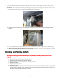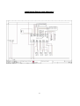
1
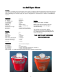
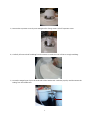
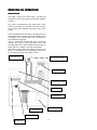
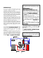
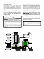
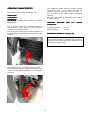
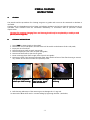
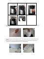
IC E B E L L
INSTALLATION AND
SERVICE MANUAL
1
TABLE OF CONTENTS
Table of contents
Specifications
page
2
3,4
GENERAL INFORMATION AND INSTALLATION
Overview (quickstart quide for end user)
Running the machine
Start-up
Removing/replacing the ice trough for installation
Draining and storing Icebell
Unpacking and inspection
Location & leveling
Electrical connections
Water supply and drain connections
Final check list
5
5
5,6,7
7,8,9
9,10
11
11
11
12
12
OPERATING INSTRUCTIONS
Start up
Operational checks
13
13
PRINCIPLE OF OPERATION
OPERATION (How it works)
Water circuit
Freezer
Refrigerant circuit
Mechanical system
Operating characteristics
Components description
Service diagnosis
Status LED
14
15
16
17
18
19,20,21,22
23,24
25
MAINTENANCE AND CLEANING INSTRUCTIONS
Cleaning instructions
Spare parts list (part numbers)
IceBell component visuals
26,27,28
29
30,31,32
SPARE PARTS FITTING INSTRUCTIONS
Compressor
Condensor/Temperature sensor
Power cable and strainer
Fan motor/ Fan blade
Pump/Motor
PCB Indicator and Box
Control electronics and housing
Header tank/lid and Water level probes
Discharge chute and insulation
Temperature sensor auger
Ice dome/Inspection cover/Ice shelf
Water trough/drain tube/overflow fitting
Side panels various
33,34
34
34,35
36
36
36
37
38
38,39
39
39
39,40
41
WIRING DIAGRAMS
Main electronics control
Control motors
42
43
2
Ice Bell Spec Sheet
Overview:
Overview:
The Icebell is a movable point of sale, display system, which is designed to chill and attractively present merchandise for
sale. The 30 litres of water used for creating ice, is continuously sanitised and re-circulated in the system, negating the
need for plumbing in to the water supply. The system is designed to run continuously for 3 months or intermittently as
required.
Dimensions:
Floor Area
Ice Trough
Ice Trough height
Overall height
Weight empty
Water Fill
Weight Total
Noise (@1m/1m high)
Min Access
Min Access
Ø660mm
Ø1060mm
985mm
1175mm
70kg
30Litres (30kg)
100kg + merchandise
56 dB
1070mm wide (assembled)
670mm wide (disassembled)
Electrical:
Voltage
Phase
Frequency
Max Current
Max Power
Max Current (illuminated)
Max Power (illuminated)
Lead (UK / Euro plug)
Fuse size
230
1
50Hz
3.97 Amps
0.91 KW
4.44 Amps
1.02 KW
2.15m
13amps
Performance:
Max Ambient
Min Ambient
Ice Production
Ice Production
Filters Change
Filters Change
General:
Supplied on 4 casters, 2 braked.
Water trough and side panels’ are user
removable to allow access through a
standard doorway.
The machine can be used in higher
ambient to a maximum of 26 Degrees, but
ice-manufacture and trough filling rate will
reduce accordingly.
THIS UNIT IS NOT INTENDED
FOR OUTSIDE USE
26C (not direct sunlight)
10C
15 minutes (start)
6 hours (full trough: dependant on conditions)
3 month (continual operation)
12 month (intermittent operation less than 3 months cumulative total)
3
SPECIFICATIONS
ICEBELL
ICEBELL COOLER
Important operating requirements:
♦
♦
MIN
Air temperature
10°C (50°F)
Electric voltage variations from voltage rating specified on nameplate -6%
MAX
26°C (90°F)
+10%
ICE MAKING CAPACITY
AIR COOLED MODELS
21°C
15°C
10°C
142
116
90
146
120
94
150
124
98
WATER
WATER TEMPERATURE (°C)
AMBIENT TEMPERATURE (°C)
10°C
21°C
26°C
26°C
ICE PRODUCED PER 24 HRS (KGS)
TECHNICAL SPECIFICATIONS
Model
Voltage
MF 120 230/50/
1
Power
(KW)
Running
amps
Starting
amps
El. Consumption
(Kwh in 24 hrs)
Compresso
r HP
Wire size
mm²
Fuse size
amps
1.1
4.44
14
13
0.9
1,5
10
NOTE. The daily ice-making capacity is directly related to the condenser air inlet temperature and age of the
NOTE
machine.
To keep your ICE
ICEBELL
BELL COOLER at peak performance levels, periodic maintenance checks must be carried out as
indicated on the last pages of this manual.
4
Icebell User Guide
Overview
The Icebell is a movable point of sale display machine, designed to cool and attractively present bottles and
cans for sale.
The machine is initially filled with 30 litres of water which is re-used over and over again to make the display
ice; therefore it is not necessary for the machine to be plumbed into a water supply.
The water and ice is continuously sanitised by a 1 micron pre-filter and special silver ion filter. However
because the ice is constantly handled by users it is NOT recommended that the ice be eaten.
The machine is designed to run for a maximum of 3 months. After this time an audible buzzer will sound. At
this point the machine MUST be cleaned and sanitised and a new set of filters fitted.
Running the machine
The machine will run continuously with little maintenance other than replenishing with new stock. However
note the following:1.
2.
3.
4.
When the machine runs in relatively high ambient humidity (> 50% RH) it will pick up water from the
atmosphere. The machine will make more ice than needed. When this occurs remove ice from the
machine as required and discard. Alternatively in low ambient humidity (circa 30% RH) the machine
may lose water to the atmosphere. In this situation add more water, 5 litres at a time, until the ice
level is restored.
The pre-filter and silver ion filter will control bacteria and slime growth in the Icebell. However in
certain conditions (very dusty atmospheres for example) and patterns of use an unsightly build up
of staining on the ice contact surfaces of the machine can occur. Periodically inspect the machine
for signs of this occurring and wipe away any deposits with a soft cloth.
After the machine has run continuously for 3 months a buzzer alarm will sound. This indicates that
the machine must be cleaned and sanitised and fitted with new filters. This should be carried out as
soon as possible after the buzzer sounds; otherwise there is a risk of infection. Either carry out the
cleaning and filter change regime as outlined in the service manual or call your service provider to
carry out the operation.
The machine can also be run intermittently if required. For example the machine could be used for
a weekend corporate event, and then stored. If used in this mode the full cleaning regime and filter
change must be carried out when the buzzer indicates a cumulative total of 3 months running has
occurred or 12 calendar months, whichever is the sooner. When used intermittently the Icebell must
be drained and prepared for storage after each period of use. Please refer to instruction ‘Draining
and storing the Icebell’
StartStart-up
1.
2.
Site the machine. (Note: - If the machine needs to be moved through a standard width door in order
to reach the intended site, the ice trough will have to be removed and replaced. Please refer to
instruction ‘Removing/replacing the ice trough in service manual’) This should only be completed
by a suitably trained person.
After unpacking the Icebell unit and before switching the Icebell on, the following conditions need
to be checked:
5
•
•
•
•
•
Is the unit in a room where ambient temperatures are within a minimum of 10°C (50°F) and 26°C
(79°F)?
Is there at least a 7.5 cm (3") clearance on the bottom of the unit for proper air circulation?
Is the unit level? (IMPORTANT)
Has the electrical connection been made?
Has the voltage been tested and checked against the data plate rating?
WARNING. This Ice Bottle Cooler is not designed for outdoor installation and will
not function in ambient temperatures below 10°C (50°F) or above 32°C (90°F). AirAirconditioned environments will also effect the Ice production of the unit.
3.
Once the above conditions are met the Icebell can be set-up for operation.
•
Slowly pour 30 litres of water directly into the Ice Trough. It is recommended that a bucket is
used to ensure that the correct measurement of water is used.
•
Remove Ice Dome by twisting off moulding, for viewing of Indicator Box.
•
•
•
•
•
•
Switch the power supply on.
All six LED’s in the Indicator Box illuminate sequentially and then flash amber.
LED 1 Flashes Green to indicate the water pump delay time
LED 4 Illuminates solid Green to indicate the fan is operational
LED 5 Flashes Amber to indicate the unit is sensing the ambient temperature.
LED 6 Illuminates Solid Green to indicate the thermistor probes are OK
6
After 1 minute (approximately), the following will happen:
• LED 1 Illuminates solid Green to indicate the water pump is ON
• LED 2 Illuminates solid Green to indicate the Gear Motor is running
• LED 3 Illuminates solid Green to indicate the Compressor is running
• LED 4 Off
• LED 5 Illuminates solid Green to indicate the Ambient temperature is OK
• LED 6 Illuminates solid Green to indicate Thermistor probes are OK
NOTE: The fan runs independently of the
the control unit as the compressor
temperature sensor controls it.
After a further 2 minutes,
minutes Ice chips should be visible in the base of the discharge chute.
The Ice-dome can now be positioned back on the unit. Twist one way to secure, ensure ice dome is sitting
flush on top off the ice shelf.
After 12 minutes (approximately) the discharge chute will be full, and Ice chips will be deposited onto the Ice
Shelf.
After 24hrs the Iceshelf should contain enough ice chips ready for the product to be displayed. Note: do not
overfill with product. We recommend between 40-50 330ml bottles to be the maximum at one time.
The Icebell can now be left until the filters need changing. For filter changes please refer to instruction within
the service manual.
Removing/replacing the ice trough
The steps for rremoving
emoving the ice trough should only be completed by a suitably trained person (service
(service
engineer).
To remove the ice trough follow these steps:
1) Remove all 3 side panels from the Icebell by unscrewing all six white fixing screws located around the
panels. (flat blade screwdriver will be required)
2) Loosen all five fixing screws located around the base of the unit. Do not completely remove
screws.(5mm Allen key will be required for this)
3) Prise out from the top and then lift out from the bottom all three sides. Carefully store to avoid
damage.
4) Remove the white ice dome moulding situated on the top of the Icebell to reveal the transparent
inspection cover moulding.
7
5) Remove the inspection cover by unscrewing the four fixing screws, Lift off inspection cover.
6) Carefully lift out Ice shelf moulding from the centre to reveal the inner of the ice trough moulding.
7) Locate the winged pipe clip on the underside of the header tank. Undo the pipe clip and disconnect the
tubing from the header tank.
8
8) Disconnect the water trough water probe leads at the male / female spade connectors in the photo
above.
9) Pull back the insulation on the tube connecting the pump to the ice trough, slacken the hose clip and
disconnect the tube. This is located on the underneath of the trough.
10) Unhook all three location clips connecting the trough to the metal support legs by lifting the latch
upwards.
11) The trough should now be free from the chassis. Carefully lift off the trough from the support legs.
12) Wheel unit into the desired position. Ensuring that the conditions laid out in start-up guide No.2 have
been considered and re-assemble unit in reverse order.
Draining and Storing Icebell
The steps for drain
(service
ice
drainin
ining
ing the icebell should only be completed by a suitably trained person (serv
engineer).
1.
2.
3.
4.
5.
6.
7.
Ensure unit has been turned off from the mains.
Remove any ice from the ice shelf and discard.
Remove the three outer side panels to reveal the chassis.
Remove ice dome
Remove inspection cover
Remove ice shelf
Locate the inlet pipe situated on the white IB500 filter. Remove this pipe from the filter. See picture
(A flat blade screwdriver will be required to loosen the clip) Position pipe over bucket or drain, this
will drain water situated within the ice trough.
9
8. Turn on power and run machine on run for a short while until all water has been drained from the
system.
9. Wipe down all surfaces of the ice trough, ice dome and both sides of the ice shelf with a clean
dampened cloth and dry thoroughly.
10. Reconnect pipe onto inlet fitting on filter.
11. Re-fit all three outer side panels.
12. Refit ice shelf, inspection cover and ice dome.
13. Cover entire machine with a plastic sheet or similar
14. Store machine in a dry and clean environment. It is recommended that if the unit is stored for more
than a year period that filters are removed and changed. For this refer to the Service Manual.
10
GENERAL INFORMATION AND INSTALLATION
A.
INTRODUCTION
This manual provides the specifications and the step-by-step procedures for the installation, start-up and
operation, maintenance and cleaning for the ICEBELL
ICEBELL COOLER.
COOLER
NOTE. To retain the safety and performance built into this icemaker, it is important that installation and
NOTE
maintenance be conducted in the manner outlined in this manual.
B.
1.
2.
3.
4.
5.
6.
7.
UNPACKING AND INSPECTION
Visually inspect the exterior of the packing box. Any severe damage noted should be reported to the
delivering carrier and a concealed damage claim form filled in subject to inspection of the contents with
the carrier's representative present.
a) Cut and remove the plastic strip securing the carton box to the pallet.
b) Cut open the top of the carton and remove the polystyrene protection blocks.
c) Carefully Lift off the outer cardboard sleeve
Inspect for any concealed damage. Notify carrier of your claim for the concealed damage as stated in step
2 above.
Remove all internal support packing and masking tape.
Ensure pallet is on level ground and cut x2 support bands that hold unit to pallet.
Lift ice bell off pallet from the base of the unit (NOTE: 2 man lifting operation 70KG)
Remove outer service panel and See data plate on support leg of the chassis, check that local main voltage
corresponds with the voltage specified on it.
CAUTION.
CAUTION Incorrect voltage supplied to the icemaker will void your parts replacement
replacement program.
C.
LOCATION AND LEVELLING
WARNING. This Ice Bottle Cooler is designed for indoor installation only. Extended periods of operation at
temperature exceeding the following limitations will constitute misuse under the terms of the SCOTSMAN
Manufacturer's
Manufacturer's Limited Warranty resulting in LOSS of warranty coverage.
1.
Position the unit in the selected permanent location.
Criteria for selection of location include:
a) Minimum room temperature 10°C (50°F) and maximum room temperature 26°C (79°F).
b) Well ventilated location for air-cooled condenser (Clean the air-cooled condenser at frequent intervals).
c) A minimum clearance of 75 mm (3") must be left at the bottom of the unit for routing cooling air drawn
into and exhausted out of the compartment to maintain proper condensing operation.
2.
Level the unit in both the left to right and front to rear directions.
D.
ELECTRICAL CONNECTIONS
See data plate for current requirements to determine wire size to be used for electrical connections. IceBell
Cooler requires a solid earth wire. The data plate can be located on the vertical support leg on the inside of the
unit. This is visible when the outer service panel is removed.
Ice Bottle Cooler is supplied from the factory completely pre-wired and requires only electrical power
connections to the wire cord provided from the bottom of the unit.
Make sure that the icebell is connected to its own circuit and individually fused (see data plate for fuse size).
The maximum allowable voltage variation should not exceed -6% and + 10% of the data plate rating. Low
voltage can cause faulty functioning and may be responsible for serious damage to the overload switch and
motor windings.
NOTE. All external wiring should conform to national, state and local standards and regulations.
NOTE
11
Check voltage on the line and the ice maker's data plate before connecting the unit.
ATTENTION. An Earth leak trip of 30mA is required
required on power line.
E.
WATER SUPPLY AND DRAIN CONNECTIONS
GENERAL
The IceBell Cooler doesn’t require any water connection.
The water reservoir must be filled up with water (max. 30 ltrs) at the time of installation.
Water containing excessive minerals will tend to produce scale build-up on the interior parts of the water
system while too soft water (with too low contents of mineral salts), will produce a very hard flakes ice.
WATER SUPPLY
To fill up the water system, pour directly the water (30 ltrs) into the Ice trough. (see start up guide, page 5)
WATER DRAIN
The IceBell Cooler can be drained via the drain tube located under the bottom of the ice trough, to drain out
the water contained into the water trough and header tank refer to (draining and storing ice bell, page 9)
F.
1.
2.
3.
4.
5.
6.
7.
FINAL CHECK LIST
Is the unit in a room where ambient temperatures are within a minimum of 10°C (50°F) even in winter
months?
Is there at least a 75 mm (3") clearance on the bottom of the unit for proper air circulation?
Is the unit level? (IMPORTANT)
Has the electrical connection been made?
Has the voltage been tested and checked against the data plate rating?
Check all refrigerant lines and conduit lines to guard against vibrations and possible failure.
Is unit full of water?
WARNING. This IceBell
IceBell Cooler is not designed for outdoor installation and will not function in ambient
temperatures below 10°C (50°F) or above 26
26°C (79
(79°F).
79
12
on the corresponding compressor copperwork
to check both the HI and LO refrigerant
pressures.
OPERATING INSTRUCTIONS
START UP
NOTE. On air cooled models, the condenser
NOTE
temperature sensor, which is located within the
condenser fins, keeps the head (condensing)
pressure between 9 and 10 bars (125÷140 psi).
In the event of condenser clogged - such to
prevent the proper flow of the cooling air - or, in
case the fan motor is out of operation, the
condenser temperature rises and when it reaches
70°C (160°F) the condenser temperature sensor
shuts-off the ice maker with the consequent lightup of the 6th LED will go solid red on the pcb
indicator.
After having diagnosed the reason of the
temperature rise and removed its cause, it is
necessary to proceed as per the previous "NOTE" to
start up again the operation of the icebell .
After having correctly installed the Ice Bottle Cooler
and connected it to the electrical connection,
perform the following "Start-up" procedure.
A.
Slowly poor 30 liters of potable water directly
into the Ice Bin.
B.
Remove ice dome moulding from unit to view
the PCB indicator box. Plug in the IceBell
Cooler to the electrical power supply and
switch on the power.
The first LED - GREEN - will glow to signal that
unit is under power.
C.
The machine starts up after approximately a
minute with the activation of the following
electrical components:
F.
WATER PUMP
GEAR MOTOR
MOTOR
COMPRESSOR
FAN MOTOR kept under control by the condenser
temperature sensor which has its probe within the
condenser fins (Replace ice dome moulding)
D.
Elapsed 5-6 minutes from the compressor start
up, observe that ice flakes begin to drop off
the ice dome and fall down onto the Ice shelf.
NOTE. The water level sensor detects the presence
NOTE
of sufficient water in the header tank and confirms
it to the PC Board by maintaining a low voltage
current flow between the sensors using the water
as conductor.
NOTE.
NOTE The first ice bits, that drop into the Ice Bin,
are not so hard as the evaporating temperature has
not yet reached the correct operating value.
It is necessary to wait about ten minutes for the
evaporating temperature to reach the correct value
so to make harder bits of ice.
WARNING. The use of dede-mineralized water (water
with no salt content) having an electrical
conductivity lower than 30 SS/cm, will cause the
CUTCUT-OUT of the machine and the glowing of the
YELLOW LED of shortage of water, even though
that water is indeed in the reservoir.
NOTE. If, after ten minutes from the compressor
NOTE
start-up, the evaporating temperature has not
dropped down to a value lower than -1°C (30°F)
due to an insufficient quantity of refrigerant in the
system, the evaporating temperature sensor detects
such an abnormal situation and stops consequently
the unit operation.
In this situation, the third LED will go solid red
red.
After having diagnosed and eliminated the cause of
the poor evaporating temperature (insufficient
refrigerant in the system or inoperative evaporator
sensor) it is necessary to push the RE
RE-SET BUTTON
located on the bottom of the PBC control box cover.
When the trough has filled up again, the 1st
LED goes solid green.
After 20 minutes the unit resumes its total
operation with the immediate start-up of water
pump, gear motor and, few seconds later, of
the compressor and fan motor.
M. If previously installed, remove the refrigerant
service gauges and re-fit the unit outer service
panel previously removed.
OPERATION CHECKS UPON THE UNIT START UP
E.
Check for the correct CUT-OUT and CUT-IN of
the header tank and trough water level
sensors.
A shortage of water into the system will cause
a gradual decrease of the water level as the
unit produces ice, as soon as the water level
gets below the sensors in the trough, the
machine pump stops to operate and the 1st
LED flashes green to signal that the machine
has run out of water.
N.
Remove condensing unit service panel and if
necessary install the refrigerant service gauges
13
Instruct the owner/user on the general
operation of the ice machine and about the
cleaning and care it requires.
PRINCIPLE OF OPERATION
WATER CIRCUIT
The water, coming from the Ice Bin, is going into
the Water Tank of the machine (maximum capacity
30 liters).
The water is pumped from the water tank to the
reservoir through the pre-filter and the IB filter.
The overflow port regulates the water level in the
Auger.
From the header tank the water is going down into
the bottom of the vertical evaporator/freezer where
it changes into ice flakes due to the exchange of
heat with the refrigerant.
The Ice, discharged through the freezer assembly
reaches the top of the discharge chute and
cascades down from the Ice dome and onto the ice
shelf, where it is used to cool down the bottles.
The water, coming from the melting ice on the ice
shelf, is collected back into the Water Trough to be
re-circulated into the entire Water System.
FREEZER ASSY
DISCHARGE CHUTE
HEADER TANK
WATER TROUGH
GEAR BOX
DRAIN HOSE
PRE FILTER
IB 500 FILTER
WATER PUMP
14
OVERFLOW
The ice, being constantly pushed up, meet the
teeth of the ice breaker, fitted on the top end of the
auger, where it gets compacted, cracked and forced
to be discharged out, through the discharge chute,
into the Ice Dome.
By running the IceBell Cooler, i.e. by putting the
unit under power, starts the automatic and
continuous ice-making process which would not
stop until all water contained into the water trough
or header tank.
When the trough or header tank is empty, the Water
Level Sensors transmit to the PC Board the signal of
NO WATER switching OFF the entire machine with
the 1st LED signaling the "NO WATER" situation by
flashing green.
green.
FREEZER
Placed on the upper side of the machine, it has the
function to change the water into ice flakes.
The water flows, from the reservoir into the bottom
inlet of the freezing cylinder, to surround the
stainless steel auger which is vertically fitted in the
center of the freezer.
In the freezer, the incoming water gets chilled into
soft (slush) ice which is moved upward by the
rotating action of the auger. The stainless steel
auger, that rotates counter-clockwise within the
freezer, is powered by a direct drive gear motor
and carries the ice upward along the refrigerated
freezer inner walls. By doing so the ice gets
progressively thicker and harder.
NOTE. The machine will restart automatically after
NOTE
20 minutes from the resume of the water level
from melted ice into the Water trough and header
tank (Switching OFF of NO WATER LED). After
approximately a minute the 1st LED will go from
flashing green to solid green. The pump will now
be re-circulating the water through the system unt.
Discharge chute
Ice breaker
Header tank
Worm Tube
Auger
Water seal
Gear motor
Bottom bearing
Coupling
15
NOTE. In case the condenser temperature probe
NOTE
senses that the condenser temperature has rised to
70°C (160°F) for one of the following abnormal
reasons:
REFRIGERANT CIR
CIRCUIT.
CLOGGED CONDENSER
OPERATION
FAN MOTOR OUT OF O
PERATION
26
78°F)
AMBIENT TEMPERATURE HIGHER THEN 2
6°C ((78
78
°F)
The hot gas refrigerant discharged out from the
compressor reaches the condenser where, being
cooled down, condenses into liquid.
Flowing into the liquid line it passes through the
drier filter, then it goes all the way through the
capillary tube where it looses some of its pressure
so that its pressure and temperature are lowered.
Next, the refrigerant enters into the evaporator coil
wrapped around the freezer inner tube.
The water being constantly fed at the interior of the
freezer inner tube, exchange heat with the
refrigerant circulating into the evaporator coil, this
cause the refrigerant to boil-off and evaporate,
thereby it changes from liquid into vapor.
The vapor refrigerant then passes through the
suction accumulator and through the suction line
where the refrigerant exchanges heat with the one
flowing into the capillary tube (warmer) before
being sucked into the compressor to be recirculated.
it causes the total and immediate SHUT-OFF of the
machine in order to prevent the unit from operating
in abnormal and dangerous conditions with the
glowing of the 3rd LED RED, HI TEMPERATURE.
To restart the ice machine it is necessary to push
the RE
RE-SET button that protrudes through the
bottom of the PCB control box cover.
The condenser temperature sensor has a further
safety function which consist in preventing the unit
from operating in Low-ambient conditions i.e.
when the condenser temperature - equivalent to
the ambient temperature - is lower then 1°C 34°F.
34°F
Even in this situation, to be able to run the
machine, after having remedied to the Lowambient condition, it is necessary to press the RE
REPush
SET P
ush Button.
The refrigerant suction or Low-pressure sets - in
normal ambient conditions - on the value of 0.9
bar (12 psi) after few minutes from the unit startup.
This value can vary of 0.1 or 0.2 bars (1.5÷3 psi)
in relation to the water temperature variations
influencing the freezer cylinder.
The refrigerant heat pressure is kept between two
pre-set values (9÷10
9÷10 barsbars-125÷140 psi)
psi by the
condenser temperature sensor which has its probe
located within the condenser fins - in air cooled
versions.
This condenser temperature sensor, when senses a
rising of the condenser temperature beyond the
pre-fixed limit, changes its electrical resistance and
send a low voltage power flow to the MICROPROCESSOR of the P.C. Board which energizes,
through a TRIAC,
TRIAC the Fan Motor in ONON-OFF mode.
NOTE. If, after ten minutes from the unit start up,
NOTE
no ice is made and the evaporating temperature
detected by the evaporator sensor results to be
higher than -1°C (30°F) the ice maker stops and the
YELLOW
Blinks.
WARNING YELLO
W LED Blinks
EVAPORATOR
FREEZER ASSSY
ACCUMULATOR
SUCTION LINE
CAPILLARY TUBE
DRIER
COMPRESSOR
CONDENSER
16
MECHANICAL SYSTEM
Too low ambient (well below the limitations of
respectively 10°C) or frequent interruptions of the
water supply to the freezing cylinder (clogging of
the water hose connecting the header tank to the
water inlet at the bottom of the freezer) or scale
deposit coming from very hard quality of the water
may cause the ice to get too hard and compact
loosing fluidity and thereby seizing the auger.
This situation will put under excessive strain and
load the entire drive system and freezer bearings.
When the gear motor rotating speed is slowed
below 1300 rpm from the normal speed of 1400
rpm the Electromagnetic Safety Device transmits an
electrical signal to the MICROPROCESSOR to stop
immediately the unit operations like for the wrong
rotation, with the 2nd LED lighting solid RED. This to
relieve from the excessive load all the electrical and
mechanical components of the entire Drive System
and extend their durability.
The mechanical system of the IceBell Cooler
consists basically of a gear motor assembly which
drives, through a ratchet coupling, a worm shaft or
auger placed on its vertical axis within the freezing
cylinder.
The gear motor is made of a single phase electric
motor with a permanent capacitor. This motor is
directly fitted in the gear case through which it
drives - in counter clockwise rotation at a speed of
9.5 rpm. - the freezer auger being linked to it by
the ratchet coupling.
NOTE. In the event of the gear motor rotating in the
NOTE
wrong direction (counterclockwise), the unit will
stop immediately and the 2nd LED will flash red, on
account of the intervention of the Electromagnetic
Safety Device - based on Hall effect principle.
After having diagnosed and eliminated the source
of the gear motor wrong rotation, to restart the
unit it is necessary to press the RE-SET push button
or switch OFF and ON the power at the mains
switch.
The icemaker will start up immediately by running
first the water pump, the gear motor and then the
compressor.
NOTE.
NOTE After having diagnosed and eliminated the
source of the gear motor slow rotation to restart
the unit it is necessary to press, the RE-SET push
button or switch OFF and ON the power at the
mains switch.
T O P B E A R IN G
AU GER
W A TE R S E AL
M A G N E T IC
S EN S O R
B O T T O M B E A R IN G
C O U P LIN G
GEAR CASE
D R IV E
MOTOR
OU TPUT SH AFT
OUTPU T GEAR
M ID D LE G E A R
17
F IB ER G EA R
The refrigerant suction pressure remains virtually
constant (0.9 bars - 12 psi) during the entire ice
making process; it may vary a bit (±0.2 bars - 3
psi) in relation to the water supply temperature
variation.
Even the amps drawn by the compressor remain at
a constant value.
OPERATING CHARACTERISTICS
The electrical components in operation are:
WATER
WATER PUMP
COMPRESSOR
GEARMOTOR
FAN MOTOR (ON-OFF mode according to ambient
temperature)
OPERATING PRESSURES
temperature)
On air cooled models the discharge pressure is
kept between 9 and 10 bars (125÷140 psi) by the
condenser temperature sensor.
The air flow to and from the air cooled condenser is
assured through the bottom louvered panel of the
machine.
Discharge pressure:
Suction pressure:
(With
21°C
ambient
9-10 bar
0.9 bar
REFRIGERANT CHARGE (R 134a): gr 38
380
NOTE. Before charging the refrigerant system
NOTE
always check the type of refrigerant and quantity as
specified on the icebell data-plate located on one
of the chassis support legs.
The exhaust hot air, coming from the condenser, is
forced to go through the louvers at the back of the
machine via the metal shroud that covers the whole
assembly.
18
temperature variations and signals them by
supplying current, at low voltage, to the P.C.
BOARD.
In case the condenser temperature sensor detects a
temperature at the condenser lower than +1°C
(33°F) the sensor signals to the PC Board to do not
start the machine till it rise up to more in line
values (+10°C).
In addition, in relation to the different current
transmitted to the P.C. BOARD, it supplies, through
a TRIAC, the power at high voltage to the fan motor
(ON-OFF mode) to cold down the condenser and
reduce its temperature.
Whenever the condenser temperature rises up to
70°C (160°F) the current arriving to the PC Board is
such to stop the machine operation.
COMPONENTS DESCRIPTION
A.
EVAPORATOR TEMPERATURE SENSOR
The evaporator sensor probe is inserted into its
tube well, which is welded on the evaporator outlet
line. It detects the temperature of the refrigerant on
the way out from the evaporator and signals it by
supplying a low voltage current flow to the P.C.
Board.
According to the current received, the microprocessor of the Control Board will let the ice
maker to continue its operation. In case the
evaporating temperature, after 10 minutes from the
unit start-up, does not drop to -1°C (30°F), the
evaporator sensor transmits a signal equal to stop
immediately the unit operation, with the 3rd LED
illuminating a solid red. In the case of a faulty
probe this will illuminate the 6th LED solid red.
NOTE. To restart the unit after the shutoff caused
NOTE
by the condenser temperature sensor, it is
necessary to push the RE-SET button on the PCB
indicator box or switch OFF and ON the switch at
mains power Supply.
B. HEADER TANK/TROUGH WATER SENSOR SYSTEM
D.
The sensor in the header tank consists of two small
stainless steel rods vertically fitted on the inner
face of the tank cover and electrically connected to
the P.C. Board. When the cover of the reservoir is
secured to the header tank the tips of both the rods
dip into the water and detects and signals its
presence by closing the electrical circuit to the PC
Board. These probes are also linked to a second set
that are located in the water trough.
This safety device is housed on top of the Drive
Motor and detects - based on Hall Effect principle the rotating speed and rotating direction of the
drive Motor.
Whenever the rotating speed drop below 1300 rpm
it transmit a signal to the PC Board to stop the unit
and light-up the 2nd LED . The same happens when
the drive motor will tend to rotate in the wrong
direction (counterclockwise) or when it doesn’t
rotate at all.
DRIVE MOTOR SENSOR
NOTE. In the case of shortage of water in the
NOTE
header tank or trough, or water too soft (demineralized with an electrical conductivity lower
than 30 SS/cm) the sensor causes the shutoff of
machine
hine, to protect it from running without
the mac
hine
water or inadequate water quality.
In this situation the 1st LED will FLASH green to
warn of the machine shutoff.
NOTE.
NOTE To restart the unit after the shutoff caused
by this safety device, it is necessary to press the
RE-SET push button or switch OFF and ON the
power line main disconnect switch.
NOTE. Anytime the machine stops for shortage of
NOTE
water it will restart 20 minutes after the resume of
the water level into the header tank and water
trough (delay automatically controlled by the PC
Board).
The 20 minutes delay time is automatically bypassed the first time at the installation of the
machine.
The P.C. BOARD,
BOARD fitted in its plastic box located to
the side of the unit, consists of a printed circuit,
which controls high and low voltage supplies. On
the top and bottom faces there are the sensors
sockets (different in colors and in size) as well as
the terminals for power IN and power OUT to the
icemaker electrical wires.
C.
F.
CONDENSER TEMPERATURE SENSOR
The condenser temperature sensor probe, located
within the condenser fins detects the condenser
19
P.C. BOARD (Data processor)
fan is operational.
3. LED 5 flashes amber to indicate the unit is
sensing the ambient temperature.
4. LED 6 illuminates solid green to indicate the
temperature sensor probes are o.k
After approximately 1 minute the following will
happen:
1. LED 1 illuminates solid green
water pump is on.
2. LED 2 illuminates solid green
gear motor is running.
3. LED 3 illuminates solid green
compressor is running.
4. LED 4 off
5. LED 5 illuminates solid green
ambient temperature is O.K
6. LED 6 illuminates solid green
Temperature probes are O.K
The P.C. BOARD is the brain of the system and it
elaborates, through its microprocessor, all the
signals received from the sensors in order to
control the operation of the different electrical
components of the icemaker (compressor, gear
motor, etc.)
G.
to indicate the
to indicate the
to indicate the
to indicate the
to indicate
For full status on all LEDs for the PCB indicator box
see page 25.
PCB Indicator Box
There are six LEDS, placed in a row, visible through
the inspection cover after removing the ice dome,
which can be used to diagnose the system status.
The system reset is on the underside of the box
and needs to be pressed and held for 5 seconds.
Also enclosed within the housing is an audible
alarm, which sounds when the unit needs the filters
changing.
H.
HEADERTANK & LID
The headertank consists of a plastic water trough,
with an overflow to maintain a constant water level
in the tank to ensure proper ice formation.
On the inner side of the headertank cover are fitted
the two water level sensors which detects the
presence or the shortage of water in the
headertank.
NOTE. It is very important to make sure of the
correct fitting of the cover on the reservoir in order
to enable the sensor to efficiently control the water
situation avoiding undue shutoff interventions.
On initial start up the following should happen:
All six LED’s in the indicator box illuminate
sequentially and then flash amber.
1. LED 1 flashes green to indicate the water
pump delay time.
2. LED 4 Illuminates solid green to indicate the
20
I.
water content so it drops onto the ice shelf as very
hard dry bits of ice.
In the icebreaker it is housed the top bearing which
is made of two rolls bearings positioned to
withstand the auger axial and radial loads. This
bearing is lubricated with a special food grade water resistant grease.
FREEZING CYLINDER (EVAPORATOR)
The freezing cylinder is made of a stainless steel
vertical tube on which exterior is wrapped around
the cooling coil with the evaporating chamber and,
in its interior, it is located the auger which rotates
on its vertical axis. A top and a bottom bearing
keep it aligned. A water seal system is located in
the bottom part of the freezer while at the top end
is fitted the icebreaker.
NOTE. It is advisable to check the conditions of the
NOTE
top bearing every six months.
K.
DRIVE GEAR MOTOR
This gear-motor is made of a single-phase electric
motor with permanent capacitor directly fitted on a
gearbox.
The drive motor rotor is kept aligned on its vertical
axis by two ball bearings permanently lubricated.
The gear case contains a train of three spur gears
with the first one in fiber to limit the noise level. All
the three gears are encased in case roller bearings
and are covered by lubricant grease (MOBILPLEX IP
44).
The water constantly flowing into the cylinder
bottom part freezes into ice when in contact with
the cylinder inner walls. The ice is then lifted up by
the rotating auger and compacted and forced out
through the opening of the icebreaker and out of
the plastic discharge chute.
J.
Two seal rings, one fitted on the rotor shaft and the
other on the output shaft keep the gear case
sealed.
However, the interior can be inspected and serviced
by unbolting the two shelves of the aluminium gear
case housing.
The gear reducer output shaft is connected to the
freezer auger by a ratched coupling which is made
of
two
toothed
halves
turning
only
in
counterclockwise direction.
ICE BREAKER
The icebreaker fitted in the freezer upper part it
has several teeth on its circle to break and squeeze
the ice.
By undergoing this, the ice looses its excess of
21
L.
FAN MOTOR
P.
The fan motor is controlled through the P.C. BOARD
and the TRIAC by the condenser temperature
sensor. Normally it operates in ON-OFF mode to
draw cooling air through the condenser fins.
In cold ambient situation, the fan motor can run at
intermittence as the condenser pressure must be
kept between two corresponding head pressure
values (9÷10 bar-125÷140 psi).
M.
Placed at the centre of the machine, it is used to
recycle the water from the Water Trough supplying
it directly to the Header tank of the machine.
COMPRESSOR
The compressor is the heart of the refrigerant
system and it is used to circulate and retrieve the
refrigerant throughout the entire system. It
compresses the low pressure refrigerant vapor
causing its temperature to rise and become high
pressure hot vapor which is then released through
the discharge valve.
N.
WATER PUMP
WATER TROUGH
The water trough is located on the upper side of
the machine and is used for housing the 30litres of
water on installation and the also the constant
water supply when the machine is in operation
On its bottom there is a drain hole to drain out the
water on servicing
O. ICE SHELF
The ice shelf is located directly on top of the water
trough, the shelf stores the ice produced and cools
down the bottles/cans that are stored within the
cascading ice. There are drainage holes situated on
the ice shelf that allows the melted ice to return
back to the water trough and be re-circulated
around the system.
22
SERVICE DIAGNOSIS
SYMPTON
POSSIBLE CAUSE
SUGGESTED CORRECTION
Unit will not run
No LED lighted-up
Blown fuse in plug
Replace fuse & check for cause of
blown fuse
Master switch in OFF position
Turn switch to ON position
Inoperative P.C.Board
Replace P.C.Board
Loose electrical connections
Check wiring
Shortage of water LED flashes green
NO. 1 LED.
Shortage or too soft water
See remedies for shortage of water or
install a mineral salt metering device
NO. 5 LED illuminates Amber
High head pressure
Dirty condenser. Clean
Inoperative fan motor. Replace
Ambient temperature too low
Move unit in warmer location
Gear motor tends to run on reverse
Check stator winding and capacitor
Too low gear motor rotating speed
Check rotor bearings, freezer bearings
and interior of freezer for scores.
Replace whatever worn or damaged.
Compressor LED illuminates RED
NO. 3 LED
Shortage or lack of refrigerant
Check and charge refrigerant system
Compressor cycles intermittently
Low voltage
Check circuit for overloading
Check voltage at the supply to the
building. If low, contact the power
company
Non-condensable gas in system
Purge the system
Compressor starting device with
loose wires
Check for loose wires in starting
device
Capillary tube partially restricted
Blow charge, add new gas & drier,
after evacuating system with vacuum
pump
Moisture in the system
Same as above
Shortage of refrigerant
Check for leaks & recharge
Pitted or stained auger surface
Clean or replace auger
Reverse rotation LED flashes red
NO. 2 LED
Low ice production
23
Wet ice
Machine runs but makes no ice
Water leaks
Excessive noise or chattering
Gear motor noise
Shortage of water
Ambient temperature too high
Move unit to cooler location
Under or overcharge of refrigerant
Recharge with correct quantity
Faulty compressor
Replace
Water not entering in the freezer
Air lock in feed line to freezer. Vent it
Clogged feed line to freezer. Clean it
Drive motor or gear stripped
Check repair or replace
Moisture in the system
Purge, replace drier and re-charge
Water seal leaking
Replace water seal
Water feed line to freezer leaking
Check and fasten hose clamp
Mineral or scale deposit on auger and
inner freezer walls
Remove and manually polish auger and inner
walls of freezer barrel using emery paper
Low suction pressure
Add refrigerant to rise suction pressure
Water feed line to freezer clogged
Vent and clean it
Worn freezer bearings
Check and replace
Worn rotor bearings
Check and replace
Shortage or poor lubricant in gear case
Check for proper lubricant opening gear case
Top of gears must be covered with lubricant
Gear case bearings and gear racers worn out
Check and replace worn parts
Float reservoir water nozzle clogged-up
Remove float valve and clean nozzle
24
STATUS LED’s
LED
1
1
1
COLOUR
Green
Green
Red
STATE
ON
Flashing
ON
REASON
Pump Running
Pump Delay Time
Water Pump Stopped
ACTION
NO
NO
Complete Shut Off
2
2
2
2
Green
Green
Red
OFF
ON
Flashing
ON
No
No
No
Complete Shut Off
2
Red
Flashing
Gear Motor Stopped
Gear Motor Runs
Gear Motor Delay Time
Gear Motor RPM wrong, Gear Motor
Stopped
Gear Motor run direction wrong, gear
motor stopped
3
3
3
3
Green
Green
Red
OFF
ON
Flashing
ON
Compressor Stopped
Compressor Running
Compressor Delay Time
Evaporator Temperature Wrong
NO
NO
NO
Complete Shut Off
4
4
Green
OFF
ON
Fan Stopped
Fan Running
5
5
Green
Amber
ON
ON
Ambient Temperature OK
Ambient Temperature Wrong
5
5
Red
Amber
Flashing
Flashing
Work Temperature >70 C
Measuring the Ambient Temperature
6
6
6
Green
Red
Red
ON
Flashing
ON
Thermistor probes are OK
Condenser Probes Faulty
Evaporator Probes Faulty
Complete Shut Off
NO
NO
25
NO
Complete Shut Off, Will
restart if the Ambient
Temperature is OK
Complete Shut Off
NO
No
Complete Shut Off
Complete Shut Off
ICEBELL CLEANING
CLEANING
INSTRUCTIONS
A.
GENERAL
The periods and the procedures for cleaning are given as guides and are not to be construed as absolute or
invariable.
Cleaning will vary depending upon local water and ambient conditions and to how long the machine remains in
operation, each icemaker must be maintained individually, in accordance with its particular location
requirements.
emoving/changing
The steps for rremoving
emoving/changing filters and cleaning should
should only be completed by a suitably trained
person (service
(service engineer).
B.
CLEANING INSTRUCTIONS
1.
2.
3.
4.
5.
6.
7.
8.
Switch OFF the Power Supply to the Icebell
Remove the service side panel.( A white sticker will be visible on the bottom of this side panel)
Empty Ice out of machine
Remove Ice Dome (refer to quick start guide)
Remove Inspection Cover (refer to quick start guide)
Remove Ice Shelf (refer to quick start guide)
Drain remaining water from trough (refer to quick start guide)
Remove pre-filter from housing and empty water. Wipe inside surfaces of the filter housing to remove
any residue. Ensure these surfaces are spotlessly clean.
Use spanner supplied to
release prepre-filter housing.
Remove filter cartridge
from housing. Empty
water and discard.
Wipe inside surfaces of
housing.
9. Refit housing without pre-filter ensuring not to damage the ‘O’ ring seal.
10. Remove the IB500 Filter and re-connect tubing by bypassing the filter. (see below)
26
1. Undo hose
connections.
3. Connect Pipes
bypassing IB500 filter
2. Disconnect Inlet
pipe from IB500
filter
3. Disconnect Outlet
pipe from IB500
filter
4. Tighten up pipe
fastener.
4. Wipe over all visible surfaces with damp cloths to remove dust, grit and grease including the inside of
the ice chute.
5. Remove Reservoir lid by removing two screws – care should be taken not to damage the two water
probes.
6. Wipe clean inner surfaces of reservoir. Inspect the probes for any scale sediment, which can be
removed with a suitable cleaning material. Re-fit lid after cleaning.
27
7. Wipe out inner surfaces of Ice Chute to remove all visible deposits.
8. Pour 5 litres of clean water into Trough. (Ensure all water connections are made)
9. Reconnect Icebell to power supply, switch on and run for 15 minutes or until Ice is visible in the
discharge chute.
10. Remove Ice and drain machine.
11. Reconnect all pipe fittings.
12. Prepare the Scotsman Ice cleaning solution by diluting in a plastic container, five litres of warm water
(40-50 C) with 0.75 litres of SCOTSMAN Ice Machine Cleaner. (Dilution rate of 15%)
13. Pour the cleaning solution directly into the ice trough. Pour a small amount into the discharge chute.
Turn on mains power to start machine.
14. The machine will start up immediately pumping the cleaning solution directly from the trough to the
header tank and then into the freezer assembly.
15. After approximately 3 minutes of machine running, turn off machine and leave for around 15mins so
the cleaning solution melts the scale deposit from the inside of the evaporator/freezer assembly.
16. After 15 minutes switch on machine again to allow it to produce the ice with the cleaning solution.
17. Leave the machine in operation for 15minutes.
18. Scoop out the ice and drain machine immediately. (refer to quick start guide)
19. Mix 5 litres of clean water with 50ml of TECare concentrate
20. Moisten a clean cloth with the mixed solution and wipe down all visible surfaces. (Includes ice shelf
and ice dome)
21. Pour the remainder of the solution into the Trough. Turn On machine long enough for Ice to be
visible in the Discharge Chute.
22. Drain the machine. (refer to quick start guide)
23. Add 5 litres of clean water. Rinse over all surfaces (includes ice shelf and ice dome) then run machine
long enough for Ice to be visible in the Discharge Chute.
24. Drain the machine. Ensure that all surfaces are spotlessly clean and rinsed free of solution.
25. Fit new Pre-Filter and IB500 filter.
26. Icebell is now ready for use. Pour 30 liters of fresh water directly into the trough.
WARNING. The SCOTSMAN Ice Machine Cleaner contains Phosphoric and Hydroxyacetic acids.
acids. These
compounds are corrosive and may cause burns if swallowed, DO NOT induce vomiting. Give large amounts
of water or milk. Call Physician immediately. In case of external contact flush with water. KEEP OUT OF THE
REACH OF CHILDREN
NOTE. DO NOT use ice produced with the cleaning solution. Be sure none remains in the bin.
NOTE
NOTE. It is recommended that both the pre-filter and the Apryon IB500 filter are replaced at the same time
NOTE
after a maximum of 3 months continuous usage.
D.
CONDENSOR CLEANING INSTRUCTIONS
INSTRUCTIONS
With the icebell turned off and the service panel removed It is recommended that when the
IB500 and pre-filter are changed that the condenser is also cleaned to eliminate the potential of any
blockages within the fins. This can easily be achieved by lightly scrubbing at the condensor fins with a
soft brush (non-metallic) and using a vacuum to remove any loose dirt. This will enable the
condenser/compressor to run efficiently. Take care not to damage temperature sensor probe.
28
ICEBELL MAINTENANCE
& SPARES
SPARES LIST
Description.
Part number.
Compressor (supplied with thermal cut out, relay,
capacitor, protective cover and clip)
Condenser
Fan Motor
Fan Blade
Water Trough
Water Trough Drain & Nut
Water Trough Strainer (Vortex breaker)
Ice Shelf
Inspection Cover
Ice Dome
Header Tank & Lid
Water Level Probes
Discharge Chute
Discharge Chute Insulation
Pump/motor
IB500 Filter
Pre Filter Housing
Pre Filter Cartridge
Control Electronics & Housing
PCB Indicator Box
Auger (inc Gearbox and Gear Motor and
insulation)
Side Panel (Brewery/plain)
Side Panel (Classic/Coke)
Condenser/Temperature Probes
Cleaning Pack
Tec Care
Ice Cleaner
Compressor Tray
Trough Overflow, Seal, Nut
29
932475-01
932476-01
932480-01
932480-02
932481-01
932518-01,02,03
932481-03
932485-01
932486-01
932487-01
932489-01,02
932490-01
932492-01
932493-01
932494-01
932495-01
932496-01
932497-01
932500-01
932499-01
932503-01
932488-01
932488-01
932501-02
932732-01
932730-01
932731-01
932475-02
932521-01,02,03
Icebell Components
Discharge Chute
PCB Indicator Box
Discharge Chute
Insulation
Gear Motor
Water Probes
Reservoir & Lid
Pump
Auger
IB500 Filter
Pre Filter Housing &
Cartridge
30
Fan Motor
Compressor
Fan Blade
Condensor
Control electronics and
housing
Temperature
sensor
Water trough overflow,
seal and nut
Water trough drain, seal
and nut
Compressor tray
Water trough strainer
(vortex breaker)
31
Ice Dome
Inspection Cover
Ice Shelf
Water Trough
Side Panel
(Brewery)
Side Panel (Classic)
32
ICEBELL SPARE PARTS FITTING INSTRUCTIONS
IMPORTANT NOTE: ALWAYS ISOLATE THE UNIT FOM MAINS ELECTRICAL SUPPLY.
ALL WORK MUST BE CARRIED OUT BY A COMPETENT SEVICE MAINTENANCE ENGINEER.
932475-01 COMPRESSOR
Turn off power to Ice bell and unscrew x6 plastic fixing screws and loosen the five bolts around the
bottom of the chassis. This will unable you to remove plastic side panels from the unit to expose the inner
chassis.
Remove the x6 m4 pozi head fixing screws (pic 1) from the metal shroud. The metal shroud can then
be lifted out of position. Take care not to damage suction line (pic 2). Lift out plastic compressor tray (pic 3).
1.
3.
2.
Using a flat blade screwdriver unclip the compressor cover (pic 4). Release all wiring by unscrewing the
cable strain relief (pic 5). Remove the relay (pic 6), also the earth cable and black wire from the thermal-cut out
connected to the compressor. The compressor should now be free from cable connections.
4.
5.
6.
Before removing/changing the compressor, Re-claim the R134a gas within the system. After the gas
has been re-claimed, un-braze the joint linking the compressor to the condenser (pic 7) then pull back the
insulation to reveal second joint to be un-brazed linking the compressor to the suction line (pic 8). Slide out
all four fixing clips from around the base of the compressor (pic 9). The compressor should now be free from
the base, lift out old compressor and discard (note: take care when handling old compressors, old joints
should be crimped before moving to minimize the potential of oil spillage.
7.
8.
9.
Un-braze x2 joints
Place over fixing holes the new compressor ensuring that it is mounted on the rubber feet to reduce
vibration and re-clip into place. Re-braze the two joints linking the compressor to the system. Vac out the
33
system, then re-charge with 380grammes of R134a refrigerant gas via the low side charge stub (Pic 10). Once
re-gassed braze over charged stub ensuring a sealed system. Re-wire unit, re-fit cover and clip into place.
Turn on machine and run for a short while leak checking the joints to ensure that they are leak free.
Re-fit plastic compressor tray and one half of the metal shroud, Ensuring that the drainage pipe from the
auger is routed through the shroud and is situated into the plastic tray beneath (pic 11). Then refit the other
half and back of the shroud. Complete the task by re-assembling the plastic outer panels to the Icebell unit.
10
.
11
.
Charge stub
932476-01 CONDENSER & 932501-02 TEMPERATURE SENSOR
Before changing the condenser, isolate unit from mains power and remove the three outer panels.
Remove the metal shroud to reveal the condenser.
Re-claim the unit (as above) before un-brazing the two joints connecting the condenser to the
compressor and condenser to the drier (pic 12) Slide temperature sensor probes from its fixing position
located on the back of the condenser and replace if required. To replace follow the wiring route back to the
control box and remove terminal from the box. Re-route the new sensor back to its fixing bracket. Ensure that
the sensor is pushed fully into the black fins of the condensor and secure with a small cable tie.
12
.
13
.
Un-braze x2
joints
Remove the two m8 fixing bolts fixing the condenser to the base plate. A 10mm spanner will be
required for this (pic 14)
The condenser should be free, carefully lift out when replacing. Re-assemble in reverse order. Again
after vac/gas charge check joints to ensure no leaks within the refrigeration system.
14
.
936336-01 POWER CABLE AND STRAINER
Isolate unit from mains power and remove the side panels. Unplug the mains cable (white cable) from
the main Control box (pic 15) and remove terminal block for re-connection (small flat-blade screwdriver will
be required). Remove the strain relief situated on the metal base with a pozi screwdriver. (pic 16) (replace
34
strain relief if damaged). Cut the x3 cable ties holding the cable to the support legs and remove old power
cable.(pic 17)
15
.
17
.
16
.
When replacing the old power cable with a new one, ensure that the cable is fed through the grommet
from the underneath of the base (pic 18) and-wire new cable onto terminal block (pic 19), push terminal block
back into main control box. Ensure cable is secured back onto support legs with new cable ties and that the
cable strainer is secured tight on the base so that the cable cannot move when pulled (pic 20). Re-fit outer
side panels.
18
.
19
.
20
.
932480-01 FAN MOTOR & 832480-02 FAN BLADE
Isolate unit from mains power and remove the side panels. Remove the three piece metal shroud to
reveal the fan motor (pic 21) The fan motor assembly bolts can be removed with a 10mm spanner (pic 22).
Unclip the wiring terminal from the main Control board (pic 23).
21
.
23
.
22
.
Cut tie holding the fan wire to the compressor base (pic24). Lift out old fan assembly (pic 25) and
remove from bracket (a 7mm spanner or 7mm nut spinner can be used)
Remove old fan blade via one fixing screw and replace fan blade if required. Ensure that the fan blade
is re-connected the right way to aid compressor/condenser cooling. (pic 26) Re-assemble fan motor back onto
bracket, Then mount the complete assembly back onto base. Re-route the cable back to main control box and
connect. Re-fit side panels to complete task.
35
25
.
24
.
26
.
932494-01 PUMP & MOTOR
Isolate unit from mains power and remove side panels. Remove all ice from shelf and trough and drain
machine (refer to Icebell cleaning instructions for draining)
Once unit has been drained disconnect pump from electronics control board (pic 27) Remove the inlet
and outlet pipe (pic 28) and drain any remaining water into a bucket. Remove the four retaining bolts that hold
the pump to the main frame of the unit. (7mm spanner will be required for this (pic 29). Replace old pump with
new and re-assemble in reverse order. Re-fill the main trough with 30litres of clean water before turning on
machine.
27
.
28
.
29
.
932499-01 PCB INDICATOR AND BOX
Isolate unit from mains power and remove all three side panels. Level ice in trough or scoop out some
ice to avoid spillage and twist off ice dome moulding (pic 30). Unscrew the transparent inspection cover with a
pozi screwdriver to reveal the PCB indicator box. Remove both sides of insulation pieces around the discharge
chute. (pic 31)
30
.
31
.
Remove the x2 fixing screws that retain the PCB box to the discharge chute (pic 32). Trace the cable
from the PCB back to the main Electronics control box and unplug terminal (pic 33). Replace old with new PCB
box and re-assemble in reverse order.
33
.
32
.
36
932500-01 CONTROL ELECTRONICS & HOUSING
Isolate unit from mains power and remove all three side panels. The main control box will be located
on the centre support tray. Remove all wiring from the control box (pic 34) and slide out from its fixing rail
from left to right (pic 35).
34
.
35
.
Slide on new Control box and connect all terminals. Important Note: Ensure all cables are connected back in
the correct orientation. (Pic 36)
Cooling fan
Pump/motor
Gear Motor
Compressor
Power cable in
Earth lead
36
Condenser
Temperature
sensor
Auger
Temperature
sensor
Water probes
Gear Motor
P.C.B
Indicator box
932489-01/02 HEADER TANK AND LID & 932490-01 WATER LEVEL PROBES
Isolate unit from mains power and remove all three side panels. Remove all ice from machine and drain
water from system. Twist off the white ice dome moulding to reveal transparent inspection cover. Unscrew the
transparent inspection cover with a pozi screwdriver (pic 37). Locate the three pipes on the underneath of the
37
header tank and loosen jubilee clips with a flat blade screwdriver to remove pipes. Remove the two top fixing
screws that connect the tank and lid. Lift out water probes from lid and replace or clean probes if required. (pic
38)
38
...
37
.
To replace the water probes trace the wiring back through the unit to the control box and remove terminal
block (pic 39). Remove the two fixing screws securing the header tank to the discharge chute and replace
header tank. Important:
Important When securing on the water tank ensure that the spacer and washer are in position.
(pic 40)
39
.
40
.
Spacer & washer
DISCHARGE CHUTE 932492-01 & INSULATION 932493-01
Isolate unit from mains power and remove ice dome moulding. Take off transparent inspection cover
by removing the four fixing screws. Remove the header tank fixing screws and the PCB indicator box fixing
screws from the discharge chute (pic 41)
Peal back two piece insulation set from around the chute and replace if required. Remove the x2 fixing bolts
with a 13mm spanner and lift off chute moulding.
41.
42
.
Apply a small bead of silicone around the top of the auger (pic 43) and push down new discharge
moulding into position. Ensure that the bolts are tightened down fully. Place back into position the two piece
insulation set and secure using masking tape. (pic 44) Re-assemble top mouldings and side panels to
complete task.
38
44.
43.
932501-02 TEMPERATURE SENSOR AUGER
To change the sensor, pull back the insulation at the top of the discharge chute to reveal the sensor
probe. Trace back the wire to the main control box and remove terminal (pic 45). Push in new probe terminal
and re-route the cable back to the probe housing (pic 46) ensuring that no cable is left trailing. The cable can
be tied to the suction line. Ensure that the probe is completely insulated and secure in position with black
electrical tape to avoid any unwanted ice forming.
45.
46.
47.
932495-01 IB FILTER & 932496-01 PRE-FILTER HOUSING & PRE FILTER CARTRIDGE
For maintenance on the above, please refer to the cleaning instruction guide.
932487-01 ICE DOME & 932486-01 INSPECTION COVER & 932485-01 ICE SHELF
To replace the ice dome level the ice off in the trough so it is beneath the whole of the dome and twist
off moulding. (pic 48)
To replace the inspection cover unscrew the x4 m5 fixings and lift off the transparent moulding. (pic
49) When replacing ensure that the inner side of the moulding has the sealing strip in place.
To replace the ice shelf firstly remove all ice visible and drain unit (refer to cleaning instructions) the
ice shelf can then be easily removed by lifting out from the inside aperture (pic 50)
48.
49.
50.
Sealing strip
932481-01 WATER TROUGH
(Also replacing 932518-01,02,03 trough drain/seal/nut & 932481-03 Water trough strainer & 93252101,02,03 Trough overflow/seal/nut)
Turn off machine and remove the ice dome moulding, inspection cover and ice shelf. (as above). This
will reveal the water trough strainer (pic 51) Important:
Important this part must be in place.
39
51.
To replace the trough drain/seal and nut the Icebell will need to be completely drained (refer to
cleaning instructions guide) locate the pipe on the underneath of the trough and pull back insulation to reveal
pipe clip. Loosen pipe clip and remove pipe (Pic 52). Lift up the water strainer on the inside of the trough to
reveal the drain fitting (Pic 53). With a spanner loosen the nut. (Pic 54) and remove old fittings and replace.
Ensure that rubber seal is on the inside of the trough when re-assembling.
52.
53.
54.
To replace the Trough overflow/seal and nut, loosen the black nut with a 32mm spanner (Pic 55). This
will disconnect the tubing from the header tank. Pull up the pipe and replace the overflow fitting (Pic 56)
56.
55.
To replace the trough remove both the overflow and drain fittings as above and unhook all three
location clips connecting the trough to the metal support legs by lifting the latch upwards (Pic 57).
The trough should now be free from the chassis. Carefully lift-off the trough from the support legs and
replace with a new one. (Pic 58)
57.
58.
932488-01 SIDE PANELS VARIOUS
40
To replace the side panels, Unscrew the white fixings located along the join of the panel. These can be
removed with a flat blade screwdriver. (Pic 59). Loosen the bottom two fixing bolts with a 4mm Allen key
located around the base of the panel to be replaced. (Pic 60)
60.
59.
Carefully prize out from the top (pic 61) and then lift out from the bottom the panel (pic 62). To replace
the panel locate the slots on the bottom of the panel onto the fixing bolts.
61.
62.
41
Icebell wiring diagram (main electronics)
electronics
42
Icebell wiring diagram (supply motors)
motors)
43