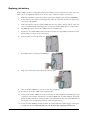
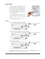
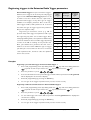
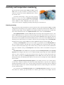
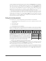
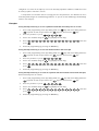
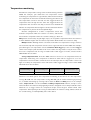
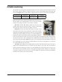
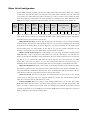
1
All the reassurance you need
Lifeline 4000
Advanced User Guide
Tunstall Telecom Ltd., Whitley Lodge, Whitley Bridge, Yorkshire, DN14 0HR.
Tel. 01977-661234 • Fax. 01977-661993 • http://www.tunstall.co.uk/
Part Number. D3607154B
Contents
1. Common Tasks
When help arrives
5
3. Programming Reference
5
Homecare Management
5
How do I register my service using my radio
trigger?
6
How do I register my non-timed service? 6
How do I enter my timed service?
7
Background information on sound
8
Local programming
9
Programming a parameter
10
Setting the unit identification number
11
Setting the clock
12
Entering the alarm telephone numbers to call
13
Registering a personal radio trigger
15
Replacing the battery
2. Common Installations
19
19
Inactivity Monitoring
20
Intruder Detection
21
Smoke and Fire Alarms
22
Temperature Monitoring
22
Opening doors
23
Witness Protection
23
Configuring Keys
Assigning key actions
Assigning Text to User Keys
Cancel button
26
29
29
25
Messages and warnings
User Options
Speech Synthesis and Language
Away reminder
30
30
32
33
Triggers
34
Registering radio triggers
36
Registering triggers in the Extension Radio
Trigger parameters
38
Setting the type for the hardwired input 43
18
Installing movement detectors
25
Trigger types and actions
44
Call Sequences
49
Inactivity and temperature monitoring
Setting the inactivity parameter
Temperature monitoring
53
55
Intruder monitoring
Entry/Exit time
Personal Identification Number (PIN)
59
59
Call configurations
Periodic Calls
Personal recipient configuration
Incoming call timeout
Mains fail call configuration
Tone dialling/pulse dialling
Ringing
Augmented ringing
60
60
62
63
64
65
66
66
Miscellaneous
Configurable date
Away state
67
68
4. External Connections
Inputs and outputs
Hardwired Input
Hardwired output
52
57
67
69
69
70
71
5. Parameter Index
73
6. Index
75
Copyright © 2000 Tunstall Group Ltd.
All rights reserved. Neither the paper-based guide, nor the electronic version of the same, nor any portion of the text and/or images, may be copied, distributed, broadcast, or
transmitted in any form or using any means howsoever, without the express written permission of Tunstall Group Ltd. Under no circumstances may the paper-based or electronic
guide be edited, amended or adapted, or used for any purpose other than as an aid to using Lifeline 4000.
Trade Marks
The following are registered trade marks: Tunstall, Amie, Talkback, Communicall, Lifeline, PNC3.
Who should read this guide?
As its name suggests, this guide explains the more advanced features of Lifeline 4000. It is a
supplement to the main Lifeline 4000 User Guide, not a replacement. This guide is intended for
interested owners/users of Lifeline 4000, care and control centre staff, as well as installers and
service engineers. For information on basic installation, operations such as raising an alarm and
answering a call, please consult the main Lifeline 4000 User Guide.
How is this guide organized?
This guide is divided into four sections
•
Common Tasks is intended for control centre staff. It explains how homecare management
entries can be made, as well as the basics of local programming.
•
Common Installations explains the various ways in which a Lifeline 4000 can be configured.
It includes explanations and configurations for inactivity monitoring, intruder detection,
door control, among others.
•
Programming Reference deals with all of the parameters in Lifeline 4000 that might be set
using local programming.
•
External Connections explains how to make connections to Lifeline 4000’s input and output
ports.
Control centres and Lifeline 4000
Full use. The Tunstall PNC3 Vision control centre (version 5.4 and above) takes advantage of the
wide variety of new features offered by Lifeline 4000. In particular, PNC3 Vision (version 5.4 and
above) can handle the high-quality two-way speech Lifeline 4000 allows. PNC3 Vision also offers
remote programming of Lifeline 4000 through its new, easy-to-use programming utility.
Normal use. Other control centres will also be able to accept calls from Lifeline 4000, even
some older non-Tunstall control centres. This is because Lifeline 4000 uses standard codes and
protocols for communication with these older centres. However, these control centres will not be
able to take advantage of the new facilities offered by Lifeline 4000, and some non-Tunstall centres
may not be able to remotely program Lifeline 4000.
Tunstall grouped alarms (also called scheme alarms), such as Haven, Communicall and
Communicall Vision can accept alarm calls from Lifeline 4000 (but only when they have either a
Telephone Interface Card (TIC) or a UAC interface to the telephone network). There is no facility in
any grouped alarm to remotely program Lifeline 4000. However, the high quality-two-way speech
offered by Communicall Vision means that it can take advantage of the high-quality two-way
speech offered by Lifeline 4000.
Copyright © 2000 Tunstall Group Ltd.
Lifeline 4000 Advanced User Guide (B)
3
4
Lifeline 4000 Advanced User Guide (B)
Copyright © 2000 Tunstall Group Ltd.
1
Common Tasks
When help arrives
When a carer or member of control centre staff
arrives at the home of someone who has raised
an alarm they need to let the control centre know
that help has arrived (once they have seen to the
immediate needs of the resident). They do this
simply by pressing the large integral alarm button
on the Lifeline 4000 to raise an alarm call, and
then speaking to the operator who answers the
call. Operators using PNC3 Vision control centres
version 5.3 and above should normally park alarm
calls where help is being sent. These parked calls/
reminders will then be displayed at the control
centre when the person who has arrived to help
makes this further alarm call from the Lifeline
4000 that made the original call.
Homecare Management
When someone arrives at a resident's home to perform a service—such as check a central heating
system, or perform a personal service, such as providing physiotherapy—they can register this
service using a Lifeline 4000, providing the Lifeline 4000 in question has been configured to make
homecare calls. There are two types of service: timed and non-timed. For a non-timed service the
provider simply enters the details into the Lifeline 4000 and the Lifeline 4000 calls the control
centre to let the computers at the control centre know that a service has been delivered. For timed
services the service provider enters their details before they provide the service, and enters further
information into the Lifeline 4000 after they have provided the service. Once the Lifeline 4000
knows that the service has been delivered it will call the control centre computers to let them
know that the service has been provided, giving the start time and end time for the service.
Copyright © 2000 Tunstall Group Ltd.
Lifeline 4000 Advanced User Guide (B)
5
How do I register my service using my radio trigger?
If you have been given a radio trigger such as a GEM or Amie for registering the service you
provide then your service can be registered with just two simple steps:
1.
Press the Home Care Primer button (this will be a radio trigger of some sort).
2.
Press your radio trigger. If you have been given more than one trigger (i.e. one for each
service you provide) then make sure you press the trigger that relates to the service you
have provided.
How do I register my non-timed service?
You will be given a four-digit personal identification number (PIN) by your control centre, just like
the ones needed to take money out of bank cash machines. Every time you deliver a service you
enter this number into the resident's Lifeline 4000. The Lifeline 4000 will pass this number onto
the computers at the control centre so that they know you have delivered your service. You will
also be given a two-digit service code for the service you provide. If you provide more than one
service you will be given a different two-digit code for each of the services you deliver. To register
your service you need to follow the four steps explained here.
1.
Press the Homecare user key on the top of
the Lifeline 4000. If the Lifeline 4000 has a
display you will see the words Enter PIN
displayed.
2.
Enter your personal identification number
(your PIN). After you have entered your PIN
the words on the display (if the Lifeline 4000
Speaker
Away
Homecare
Jenny
Dr Hill
Jackie
Pat
Intruder
has one) will change to PIN Entered Service
Code ??
3.
Enter the two digit service code. If the Lifeline
4000 has a display it will then display the
words Resident ?
4.
If the service is for a resident then enter the
number for the resident who is receiving the
service and then press the
#
key. If the
service is not for any particular resident then
just press the
#
key without entering a
resident number. If the Lifeline 4000 has a
display it will display the words Service
Complete.
6
Lifeline 4000 Advanced User Guide (B)
Copyright © 2000 Tunstall Group Ltd.
How do I enter my timed service?
A timed service is just like a non-timed service, except that you must enter your PIN before you
deliver the service, and enter your service code again to let the Lifeline 4000 know when you have
finished the service. The main difference is that you press the
always pressing the
#
key for some entries instead of
key, as you would for a non-timed service. You need to follow the five
steps explained here.
1.
Press the Homecare user key on the top of
the Lifeline 4000. If the Lifeline 4000 has a
display you will see the words Enter PIN
displayed.
2.
Enter your personal identification number
(your PIN). After you have entered your PIN
Speaker
Away
Homecare
Jenny
the words on the display (if the Lifeline
4000 has one) will change to PIN Entered
Dr Hill
Jackie
Pat
Intruder
Service Code ??
3.
Enter the two digit service code. If the
Lifeline 4000 has a display it will then
display the words Resident ?
4.
If the service is for a resident then enter
the number for the resident who is receiving
the service and then press the
key. If
the service is not for any particular resident
then just press the
key without
entering a resident number. If the Lifeline
4000 has a display it will show the words
Service Started.
5.
When you have delivered the service press
the Homecare user key on the top of Lifeline
4000. Enter your PIN and press # , and then enter the service code as before. This time,
however, you press the
#
key, not the
key. This ends the service, and the Lifeline
4000 will pass the information back to the computers at the control centre.
What if I arrive when someone else is also delivering a timed service, do I have to wait? Lifeline 4000
can time up to five different services at once. Consequently, you would only have to wait if five
service providers were already each present providing a timed service.
What if I forget to enter the end of my timed service? Lifeline 4000 will do nothing with your
service information until you enter the end of the timed service. If after 24 hours you have still not
entered the end of your timed service then Lifeline 4000 will assume that you have forgotten
about the service and will remove it from its memory without making a call to the control centre.
Will my service information always reach the control centre? Unlike alarm calls, Lifeline 4000 will
only make one call to a control centre with service information. This is to ensure that the Lifeline
4000 is available for alarm calls. In the unlikely event that the call does not get through to the
control centre the information on the service will be lost.
Copyright © 2000 Tunstall Group Ltd.
Lifeline 4000 Advanced User Guide (B)
7
Background information on sound
Augmented ringing
The ringing volume can be altered using the buttons
on top of the Lifeline 4000 (see the main Lifeline
4000 user guide). The volume can be set as high as
volume 5 (see table). However, there are two further
volume settings, volumes 6 and 7, that cannot be
reached using these buttons. These higher volumes
are used during augmented ringing. Augmented
ringing is where the volume of the ringing gets louder
the longer a telephone call goes unanswered. In
short, volumes 6 and 7 are used only when a
telephone call is unanswered.
Speech volume
The volume of speech can be altered during a call using the volume buttons
Volume 7
on the top of the Lifeline 4000 (see the main Lifeline 4000 user guide).
Once again, the volume can be set as high as volume 5. The user cannot set
Volume 6
the Lifeline 4000 to use volumes 6 and 7. These volumes are only used if a
Volume 5
call operator at a PNC3 control centre selects Increase Volume from their
Volume 4
Call menu during a call.
Volume 3
Volume 2
Volume 1
8
Lifeline 4000 Advanced User Guide (B)
Copyright © 2000 Tunstall Group Ltd.
Local programming
What is local programming?
The term programming simply means changing the settings inside a Lifeline 4000. These settings
include, for example, the telephone number of the control centre to call.
Lifeline 4000 can be programmed in three ways. First, control centre staff using version 5.4
and above of PNC3 Vision can change many of the settings inside a Lifeline 4000 during a telephone
call. Second, Tunstall Service Engineers, using the Lifeline 4000 Engineer's software application,
can change almost all of the settings inside a Lifeline 4000.
Finally, some settings can be programmed just using the
buttons on a Lifeline 4000 together with the number keys
under the flap. This last method is called local programming.
This guide explains all the settings that can be altered using
local programming. The Programming Reference which forms
chapter 3 also includes explanations of some parameters that
cannot be altered.
Displays and card inserts
Anything that can be programmed locally on a Lifeline 4000 with an LCD display can also be
programmed on a Lifeline 4000 with the card insert. However, it is difficult to check your entries
without a display. For this reason it is best if you program Lifeline 4000s that do not have a display
using either the Lifeline 4000 Engineer's software application, or via PNC3 (version 5.4 and above),
rather than rely upon local programming methods. All of the examples below assume that you are
programming a Lifeline 4000 with a display.
Speaker
Paul
Julie
Jenny
Display
Away
Intruder
Dr Jones
Pat
Card Insert
What is a parameter?
You may sometimes hear engineers mention parameters or variables. Lifeline 4000 has a wide
range of parameters that can be altered. You can think of parameters as small boxes inside Lifeline
4000 that hold information. For example, one box (parameter) holds the first telephone number
that Lifeline 4000 will call to raise an alarm. Another parameter holds the Lifeline 4000's unique
identification number (its unit ID). When you program a parameter in Lifeline 4000 you change its
value. In other words, you change the information inside the box.
Copyright © 2000 Tunstall Group Ltd.
Lifeline 4000 Advanced User Guide (B)
9
Programming a parameter
There are four major steps involved in programming a parameter.
•
Enter local programming mode.
•
Enter the number of the parameter you wish to alter.
•
Delete the present value in the parameter and enter a new value.
•
Leave local programming mode.
Enter local programming mode
1.
Press and hold
hold
2.
, and then also press and
# .
Keep holding the keys down until you hear Lifeline
4000 beep (after about two seconds).
3.
Release the
4.
Then release the
5.
The words Local Programming will display on the display.
#
key.
key.
Enter the number of the parameter you wish to alter
6.
To enter a parameter press the
key. You will then hear another beep and the word
Param will be shown if the Lifeline 4000 has a display.
7.
Enter the number of the parameter you wish to change and then press the
key. The display
will either show the word Programmed. Lifeline 4000 will beep and then wait for a valid
parameter if you enter an invalid number.
Delete the present value in the parameter and enter a new value
8.
Press the C
key to delete the present value in the parameter (for the display version only).
9.
Enter the new value for the parameter and press the
key.
10. Lifeline 4000 will then beep and the display will then show Programmed.
Leave local programming mode
11. You can leave local programming simply by pressing the Cancel key. If you want to program
another parameter then do not press the Cancel key, press the
key to enter the number
of the next parameter you wish to program (this takes you back to step 6 in the procedure
above).
10
Lifeline 4000 Advanced User Guide (B)
Copyright © 2000 Tunstall Group Ltd.
Cancel and the C key
Note that the Cancel key is the
green key marked with a letter
C, beside the red integral alarm
button on Lifeline 4000. The
C
key is the black key under
the flap, between the
and the
D
B
key
key.
Ending programming
If you wish to end or abort the programming then press the Cancel key at any time. If you press the
Cancel key after a parameter has been accepted then this will not remove the value you have
entered. If you change your mind after programming a parameter then you need to program the
parameter again with the value you replaced.
There are other ways in which Lifeline 4000 will switch out of local programming mode. If you
do not press any key for more than 2 minutes then the Lifeline 4000 will start to beep. After 10
seconds of beeping the Lifeline 4000 will switch out of programming back into its normal waiting
mode. Lifeline 4000 will also automatically switch out of local programming mode if an alarm is
raised.
Incoming calls. If someone calls the telephone line to which the Lifeline 4000 is connected then
you will need to press the Cancel button to cancel programming, and then press the Cancel button
again to answer the call.
Setting the unit identification number
The unit identification number is the unique number you can program into each Lifeline 4000. This
number is also sometimes called the equipment identification number. This is the number that the
Lifeline 4000 will transmit to a control centre to identify itself, and can be up to 12 digits long. If
you are programming the Lifeline 4000 for Mrs Jones of 34 Holbeck Terrace, Cromwell, then you
should ensure that the number you enter as the equipment identification number matches the
number in the control centre database for Mrs Jones of 34 Holbeck Terrace. For more information
on this see Chapter 5 in Volume A of the PNC3 Vision control centre manual.
To program this parameter:
1.
Enter local programming mode by holding down the
#
key until the unit beeps. Release the
#
key and then holding down the
key first, and then the
2.
Enter the parameter—press
3.
Delete the old value using the
4.
Enter the new value (the new identification number) and then press
5.
End local programming by pressing the Cancel key.
2
C
key.
.
key (display version only).
.
Once you have entered the new identification number you should make a test alarm call. You can
then speak with a call operator and check that the information that appears on the control centre
screens matches the dwelling and the residents.
Copyright © 2000 Tunstall Group Ltd.
Lifeline 4000 Advanced User Guide (B)
11
Setting the clock
Lifeline 4000 has a 24-hour clock. In other words,
9.30am is displayed as 09:30. 10.15pm is displayed as
22:15. To set the time you need to enter programming
mode, select parameter 171, and then enter the time as
a four-digit number.
Examples
Setting the time to 9.35am
1.
key and then holding down the
Enter local programming mode by holding down the
#
key until the unit beeps. Release the
key first, and then the
#
.
2.
Enter the parameter—press
3.
Delete the old value using the
4.
Enter the new value
5.
End local programming by pressing the Cancel key.
0
9
7
1
C
key.
1
key (display version only).
3
and then press
5
.
Setting the time to 1pm
1.
key and then holding down the
Enter local programming mode by holding down the
#
key until the unit beeps. Release the
key first, and then the
#
2.
Enter the parameter—press
3.
Delete the old value using the
4.
Enter the new value
5.
End local programming by pressing the Cancel key.
1
3
7
1
C
key.
.
1
key (display version only).
0
and then press
0
.
Setting the time to 10.48pm
1.
Enter local programming mode by holding down the
#
12
key until the unit beeps. Release the
key first, and then the
#
2.
Enter the parameter—press
3.
Delete the old value using the
4.
Enter the new value
5.
End local programming by pressing the Cancel key.
2
2
7
1
C
4
key and then holding down the
1
key.
.
key (display version only).
8
and then press
Lifeline 4000 Advanced User Guide (B)
.
Copyright © 2000 Tunstall Group Ltd.
Entering the alarm telephone numbers to call
The Lifeline 4000 has space for ten different telephone
numbers to call if an alarm is raised. Each number can be
the telephone number of a control centre, or the
telephone number of an individual (a personal recipient).
If Lifeline calls a control centre then it will
communicate with the computers at the control centre
using a series of electronic tones. If Lifeline calls an
individual it will announce either the unique ID (the
equipment identification number), or it will play the
message that has been recorded into it. For more
information on recording messages for personal recipients
see the main Lifeline 4000 User Guide. However, Lifeline
needs to know whether it is calling a personal recipient
(an individual) or a control centre, so that it knows
whether to play a message or communicate using
electronic tones.
Lifeline assumes that its first two telephone numbers
are control centre numbers. It assumes that the latter eight numbers are personal recipient telephone
numbers. In other words, Lifeline assumes that the number in parameter 0 is the number of a
control centre. Lifeline also assumes that the number in parameter 1 is the number of a control
centre. If it calls either of these telephone numbers it will attempt to communicate using electronic
tones.
Lifeline assumes that the numbers in parameters 7, 8, 9, 10, 39, 40, 41, 42 are all telephone
numbers for personal recipients. If you look at the table of parameters and telephone numbers
you can see that these are the parameters for the latter eight telephone numbers.
Changing Lifeline’s assumption. Given that Lifeline assumes that the first two telephone numbers
are control centres, and the latter eight are the numbers of personal recipients, what do you do if
you want to enter a third control centre number? The answer
is that you put a # character before the number, by pressing
Parameter
Telephone Number
key. If you look at the table you can see that the
0
01977662551
telephone number for parameter 7 has a # character in front
1
01652628001
7
#01634647783
treat these first two numbers as personal recipients, instead
8
01634642783
of treating them as control centres.
9
01634647223
10
01634647111
39
01634643946
possible, in the same way as older pieces of equipment. This
40
01634649822
makes it easier for control centres with old control centre
41
the
#
of it. Likewise, if you put a # character in front of either of the
first two telephone numbers (parameters 0 and 1) Lifeline will
How are parameters numbered? You might wonder why these
parameters have such different numbers. Why not number them
1 to 10? The answer is that parameters are numbered, where
software to program Lifeline 4000. As long as you know the
correct parameter number you do not need to pay any attention
42
to how they are numbered.
Copyright © 2000 Tunstall Group Ltd.
Lifeline 4000 Advanced User Guide (B)
13
Examples
Programming the first alarm telephone number
1.
Enter local programming mode by holding down the
#
key until the unit beeps. Release the
#
key and then holding down the
key first, and then the
2.
Enter the parameter—press
3.
Delete the old value using the
4.
Enter the new value (the new telephone number) and then press
5.
End local programming by pressing the Cancel key.
0
C
key.
.
key (display version only).
.
Programming the second alarm telephone number
1.
Enter local programming mode by holding down the
#
key until the unit beeps. Release the
#
key and then holding down the
key first, and then the
2.
Enter the parameter—press
3.
Delete the old value using the
4.
Enter the new value (the new telephone number) and then press
5.
End local programming by pressing the Cancel key.
1
C
key.
.
key (display version only).
.
Programming the second alarm telephone number to call a personal recipient
1.
Enter local programming mode by holding down the
#
key until the unit beeps. Release the
#
key first, and then the
2.
Enter the parameter—press
3.
Delete the old value using the
4.
Enter
5.
End local programming by pressing the Cancel key.
#
1
C
key and then holding down the
key.
.
key (display version only).
and the new value (the new telephone number), and then press
.
Programming the third alarm telephone number
1.
Enter local programming mode by holding down the
#
key until the unit beeps. Release the
#
key and then holding down the
key first, and then the
.
2.
Enter the parameter—press
3.
Delete the old value using the
4.
Enter the new value (the new telephone number) and then press
5.
End local programming by pressing the Cancel key.
7
C
key.
key (display version only).
.
Programming the fourth telephone number as a control centre number
1.
Enter local programming mode by holding down the
#
14
key until the unit beeps. Release the
#
key first, and then the
2.
Enter the parameter—press
3.
Delete the old value using the
4.
Enter
5.
End local programming by pressing the Cancel key.
#
8
C
key and then holding down the
key.
.
key (display version only).
and then the new value (the new telephone number), and then press
Lifeline 4000 Advanced User Guide (B)
.
Copyright © 2000 Tunstall Group Ltd.
Registering a personal radio trigger
Lifeline 4000 can accept radio inputs from Amie and GEM personal triggers, as well as the Fall
Detector trigger. For background information on how radio triggers work with Lifeline 4000 please
see the Lifeline 4000 User Guide.
Lifeline can also accept radio input from other devices. For example, alarm pull cords, smoke
detectors, temperature monitors and many other types of device can each be linked to a Tunstall
Radio Output Module to allow them to send radio signals to Lifeline. This can save on the cost and
inconvenience of installing wires. This section deals only with registering Amie and GEM personal
radio triggers. See the section on triggers in the Programming Reference in chapter 3 for
information on registering and configuring different types of trigger.
Amie
GEM
Fall Detector
How does Lifeline know which radio triggers belong to it?
Each radio trigger has an identification number automatically entered into it when it is made at
the factory. When a radio trigger is set off it transmits this identification number. Lifeline listens
for any radio transmissions on a particular frequency. If it detects a signal it checks the number
that has been sent. Next, Lifeline looks through each of the parameters that hold radio trigger
identification numbers to see if there is a match between the number it has received and one of
the numbers in its memory. In other words, Lifeline asks the question, Does the transmitted number
match the number of any of the radio triggers that belong to me?
Registering a trigger
To register a radio trigger all you have to do is enter its
Parameter
identification number in one of the radio trigger
parameters. This is a simple two-step process. First, you
Personal Trigger 1
21
select a parameter, and then you press the alarm button
Personal Trigger 2
27
Personal Trigger 3
28
on the GEM or Amie radio trigger. Lifeline listens for the
number that is transmitted and puts it into the parameter
you have selected.
More than three personal triggers
You can have more than three personal radio triggers registered to one Lifeline 4000 if needed. In
total, you can have up to 18 personal triggers. To register further triggers you need to consult the
section on triggers in the Programming Reference in chapter 3.
Copyright © 2000 Tunstall Group Ltd.
Lifeline 4000 Advanced User Guide (B)
15
Examples
Programming Personal Trigger 1
1.
Enter local programming mode by holding down the
#
key until the unit beeps. Release the
#
key and then holding down the
key first, and then the
key.
2.
Enter the parameter—press
3.
Press the alarm button on the radio trigger. Lifeline will beep and the words Trigger registered will
2
.
1
be announced, and the words Programmed will be displayed if the unit has a display.
4.
End local programming by pressing the Cancel key.
Programming Personal Trigger 2
1.
Enter local programming mode by holding down the
#
key until the unit beeps. Release the
#
key and then holding down the
key first, and then the
key.
2.
Enter the parameter—press
3.
Press the alarm button on the radio trigger. Lifeline will beep and the words Trigger registered will
2
.
7
be announced, and the words Programmed will be displayed if the unit has a display.
4.
End local programming by pressing the Cancel key.
Clearing Personal Trigger 2
1.
Enter local programming mode by holding down the
#
key until the unit beeps. Release the
#
key first, and then the
2.
Enter the parameter—press
3.
Press
4.
End local programming by pressing the Cancel key.
2
key and then holding down the
key.
.
7
.
Programming Personal Trigger 2 with a Fall Detector
1.
Enter local programming mode by holding down the
#
key until the unit beeps. Release the
#
key and then holding down the
key first, and then the
key.
2.
Enter the parameter—press
3.
Press the alarm button on the radio trigger. Lifeline will beep and the words Trigger registered will
2
7
.
be announced, and the words Programmed will be displayed if the unit has a display.
4.
16
End local programming by pressing the Cancel key.
Lifeline 4000 Advanced User Guide (B)
Copyright © 2000 Tunstall Group Ltd.
Test the radio trigger
You must always test a radio trigger after you
have registered it with a Lifeline 4000. It is
always possible that the Lifeline did not
receive the trigger number successfully.
Alternatively, it may have received another
number just before you pressed the radio
trigger alarm button (this is unlikely, but it
can happen).
If you register a Fall Detector then you
must test that it can detect a fall, by jolting
it and tipping it on its side. Testing is essential.
Failing to register
When you register a radio trigger you will
normally hear a high-pitched beep from the Lifeline 4000. If you hear a low tone then the registration
has failed. The most common reason for such a failure is that the radio trigger is already registered
with the unit. If a trigger is already registered in the parameter for Personal Trigger 1 the Lifeline
4000 will not allow you to register it in the parameter for Personal Trigger 2.
Registering with more than one home unit
It is not recommended that you register a radio trigger with more than one home unit. However,
it is possible. If, for example, a person lived in two properties, each with a Lifeline 4000, then it is
possible for them to have one or more triggers registered with both units.
Copyright © 2000 Tunstall Group Ltd.
Lifeline 4000 Advanced User Guide (B)
17
Replacing the battery
Lifeline 4000 contains a rechargeable battery. This allows the unit to function for some time if the
mains electricity supply has failed. These are the steps required to replace the battery:
1.
Make sure you have a replacement battery from your supplier (part number D3606005).
2.
If they battery cover has been damaged then make sure you have obtained a replacement
cover from your supplier.
3.
Find a flat surface near the Lifeline 4000, and cover the surface with a cloth or other soft
cover to avoid marking or damaging the front of the Lifeline 4000 when it is turned over.
4.
You must disconnect the Lifeline 4000 from the telephone line.
5.
Disconnect the Lifeline 4000 connected from its mains electricity adaptor, and turn the unit
upside down, resting it on the soft surface.
6.
Push and slide the battery cover off.
7.
Carefully remove the battery and unplug it.
8.
Plug in the new battery and replace the battery cover.
9.
Turn the Lifeline 4000 over, so that it is the correct way up.
10. Reconnect the Lifeline 4000 to the telephone line.
11. Test the new Lifeline 4000 battery by connecting the mains adaptor and allowing the unit
to charge for six minutes. Disconnect the Lifeline 4000 from its mains adaptor. The alarm
button should remain lit for several seconds. If the alarm button does not remain illuminated
for at least three seconds then you may require another battery.
12. Test the Lifeline 4000 by raising an alarm call, preferably with a radio trigger or using the
integral button. It is essential that you test the unit after replacing the battery.
18
Lifeline 4000 Advanced User Guide (B)
Copyright © 2000 Tunstall Group Ltd.
2
Common Installations
This chapter presents a list of common installations. It explains the various factors you might wish
to consider for each installation, and directs you to the parameters you need to adjust.
Installing movement detectors
You may need to install movement detectors for inactivity monitoring and intruder detection. If
properly configured, movement sensors, such as PIRs and pressure mats, can be used for both
intruder detection and inactivity monitoring. You might wish to consider the following:
1.
Lifeline 4000 can be made to beep every time it receives a trigger from a movement sensor.
This facility is only intended for installation, and can be set using parameter 48 (see Intruder
Monitoring on page 57).
2.
Register a movement detector with the Lifeline 4000 before you attach it to a wall, ceiling
or floor. For example, if you wish to use a PIR movement detector you should register it
prior to drilling holes in a wall to mount it. This can save time if the PIR is faulty. More
importantly, you should test that the Lifeline 4000 can receive radio signals from the PIR
when the PIR is in position (but before you have drilled any holes). If a thick concrete beam
or metal cabinet is between the PIR and the Lifeline 4000 then there is a chance that the
radio signal will not get through, and you will have to select a different place to mount the
PIR.
3.
If you are installing several movement detectors then consider registering these triggers as
Extension Radio Triggers rather than as triggers in the predefined parameters. The advantage
of Extension Radio Triggers is that they can also contain location information (see page 38),
which can be particularly useful in dealing with alarms and identifying the cause of repeated
false alarms.
4.
Do not register a movement detector as an intruder trigger. Intruder triggers are the sorts
of sensors that detect whether a pane of glass has been broken. A movement sensor
registered as a movement detector is more flexible—it can be used for both inactivity
monitoring and intruder detection (see the section on Trigger Types and Actions on page
44). You also have the option of registering it as an Entry/Exit type of movement sensor,
which provides time for arming and disarming an intruder alarm.
Copyright © 2000 Tunstall Group Ltd.
Lifeline 4000 Advanced User Guide (B)
19
Inactivity Monitoring
If you intend to configure a Lifeline 4000 for inactivity monitoring then you may wish to look at
the points raised in the previous section on installing movement detectors. In addition, there are
the following points to consider:
1.
A Lifeline 4000 that is set up to monitor inactivity should
normally have an Away key (see the section on Configuring
Keys on page 25). If you are concerned that the resident
might accidentally turn the monitoring off using an obvious
Away key then consider making the key labelled
A
under
the flap the Away key. If you do this you should make a note
of this in the table of settings you leave with the unit, and
you might also wish to apply a note to the underside of the flap covering the number keys.
2.
Inactivity monitoring is more reliable if more than one movement sensor is fitted. However,
one movement sensor in a key place, such as a hall or landing, will usually still perform well.
3.
Do not use a PIR type of movement sensor in a resident’s bedroom to detect inactivity. The
small movements made by a bed-bound resident who is ill and requires attention are usually
enough to trigger the sensor and ensure that help is not summoned.
4.
See the section on Inactivity and Temperature Monitoring in the following chapter (page
52). For historical reasons, inactivity monitoring is enabled using the User Options parameter
(see page 30).
5.
If you have previously configured older equipment for inactivity monitoring, you should be
aware that Lifeline 4000 has more sophisticated methods for deciding when a resident has
been inactive.
Cancelling an inactivity call
Before Lifeline 4000 makes an inactivity call it will warn the resident. It will announce, An inactivity
call is about to be made. Please press Cancel. It will then wait ten minutes before making the call,
and during this time it will repeat the announcement every 30 seconds. This warning gives the
resident chance to cancel the inactivity call, and so reduces the chance of a false alarm. However,
it is important that residents with inactivity monitoring are given three important pieces of
information:
1.
The resident must be told the Inactivity Time setting programmed into their Lifeline 4000.
The resident should know for how long they can be inactive before a call is raised.
2.
The ten minute gap between the inactivity warning and the call being made to the control
centre must be explained, although it should also be emphasized that they should not rush
to cancel the call. If they are too late they can always
raise an alarm by pressing the integral button on their
Lifeline 4000 and let the operator who answers the
call know that they do not need assistance.
3.
When a resident visits friends or relatives, and even
when a resident goes to the shops, the resident must
use the Away feature to disable inactivity monitoring.
20
Lifeline 4000 Advanced User Guide (B)
Copyright © 2000 Tunstall Group Ltd.
Intruder Detection
If you intend to configure a Lifeline 4000 for intruder
detection then you may wish to look at the points raised in
the first section in this chapter on installing movement
detectors. In addition, there are the following points to
consider:
1.
A Lifeline 4000 that is set up to detect intruders
should always have an Intruder key (see the section
on Configuring Keys on page 25). You can set either
the A , B , C
or D
key under the flap to be
the Intruder key if you wish, although if you do this
you will need to make a note of this, possibly leaving
a sticky label on the underside of the flap covering
the number keys. Using one of the keys under flap
can be helpful given that the user has to lift the flap
anyway to disable the intruder alarm. This can also make more of the user keys available for
use as Fast Dial keys.
2.
Make sure that the movement detector trigger types are set for intruder detection (see the
Trigger Uses digit in the Trigger Types and Actions section on page 44).
3.
If security is a major concern then make sure that the Intruder and Movement trigger types
are set to have no visual indications of a call, nor should they make any sounds (see Trigger
Types and Actions on page 44). You might also turn off speech synthesis and other sounds
(see Messages and warnings on page 30).
4.
If you need to flash or illuminate a light, or sound a siren, the external output can be
triggered (see Trigger Types and Actions on page 44 for details of switching the external
output, and chapter 4 for details of making an external connection).
5.
If you require the Lifeline 4000 to call a different series of alarm numbers when an intruder
alarm is raised then:
•
See Entering the Alarm Telephone Numbers to Call in chapter 1, page 13, for
information on how to enter alarm telephone numbers to call.
•
See Call Sequences on page 49 for how to program a call sequence.
•
See Trigger Types and Actions on page 44 for how to select the call sequence to
use.
Copyright © 2000 Tunstall Group Ltd.
Lifeline 4000 Advanced User Guide (B)
21
Smoke and Fire Alarms
1.
If you decide to register a number of smoke alarms with a Lifeline
4000 you might wish to use the Extension Radio Trigger parameters
(see page 38) as these allow you to set location codes. This information
is likely to be of value in a large house, both to the fire brigade in the
event of a fire, and to the control centre in tracking down any faulty
alarms.
2.
If you want Lifeline 4000 to call a different set of telephone numbers
when a smoke alarm is triggered then:
•
See Entering the Alarm Telephone Numbers to Call in chapter 1, page 13, for
information on how to enter alarm telephone numbers to call.
•
See Call Sequences on page 49 for how to program a call sequence.
•
See Trigger Types and Actions on page 44 for how to select the call sequence to
use.
Temperature Monitoring
Temperature monitoring requires temperature sensing
devices that can detect when a set temperature has been
exceeded and emit a radio trigger signal. Normally, these
sensors should trigger just once when the set level is
passed. If the sensor continually transmits its signal it
will raise a false alarm when the resident returns from
being away, switches from Away to Home, thus enabling
temperature monitoring. You might also wish to consider
the following:
1.
Registering radio triggers is dealt with on page 34
in the section on Triggers.
2.
If you need to use a number of temperature sensors
you can use the Extension Radio Trigger parameters,
and these will also allow you to enter location
information (see page 38).
3.
You might wish to set a long prealarm delay for
this sort of trigger, to allow anyone present to cancel the alarm and deal with the problem.
To adjust the prealarm delay see the Trigger Types and Actions section on page 44.
4.
If either of your temperature settings are only configured during an Away state or a Home
state then you must ensure that one of the user keys is set to be an Away key (see Configuring
Keys, page 25).
5.
22
See page 55 for further details regarding temperature monitoring.
Lifeline 4000 Advanced User Guide (B)
Copyright © 2000 Tunstall Group Ltd.
Opening doors
Lifeline 4000 can be configured to open a door using a relay connected to its external output.
1.
For details of how to make a connection to the external output see chapter 4.
2.
For information on naming a user key and setting the key type to Relay, see Configuring
Keys on page 26.
3.
The section on Configuring Keys also explains how to control the external output using a
key. A user key should be set to toggle the output, so that pressing it once opens the door,
and pressing it again locks the door.
4.
It is possible that the resident could easily leave a door unlocked, and so you might consider
some sort of visual confirmation of state, such as a light connected to the relay.
Witness Protection
Lifeline 4000 can be configured to raise
an alarm if a resident believes they are
under threat. The following steps
should be considered:
1.
Turn off any visual confirmation
of a call being made. See Trigger
Types and Actions on page 44.
2.
Turn warnings and speech
synthesis off (see Warnings and
messages, page 30).
3.
If any alarm calls are to be made
to personal recipients you might
want to silence these announcements at the Lifeline 4000 (see personal recipient
configuration, page 62).
4.
If you are considering a hardwired input then you might wish to select one where the circuit is
normally closed (i.e. the circuit is normally made). If this sort of trigger is ripped out by an intruder
the circuit will disconnect and an alarm will be raised anyway. See chapter 4 for information on
making a hardwired connection. See page 43 for how to configure the hardwired input.
5.
An intruder might use the Cancel button on the Lifeline 4000 to cancel an alarm call. This
button can be disabled. See page 29 for more information.
6.
An intruder might disconnect the telephone line before entering the house or flat. Lifeline 4000
can be configured to make periodic calls. The gaps between these calls can range from 99 days to
just 1 minute if the high resolution option is used. If a person was at serious risk you might wish
to set the telephone to call in with an automatic, silent call every ten minutes.
Fall Detector. If you are concerned that an individual may be attacked then a Fall Detector could be
a useful precaution. If the resident is knocked to the ground it will automatically raise an alarm. In
addition, it will be difficult for an intruder to forcefully take the Fall Detector from the resident
without setting it off.
Copyright © 2000 Tunstall Group Ltd.
Lifeline 4000 Advanced User Guide (B)
23
24
Lifeline 4000 Advanced User Guide (B)
Copyright © 2000 Tunstall Group Ltd.
3
Programming Reference
Some topics are dealt with in the main user guide for the Lifeline 4000. Specifically, changing the
ringing volume, altering the volume of speech during a call, and entering fast dial numbers. Other
basic topics have been explained in Common Tasks (chapter 1 of this guide). These include, registering
a personal radio trigger, setting the equipment identification number, setting the time for the
internal clock, and entering the telephone numbers to call when an alarm is raised.
Configuring Keys
Each User Key on the Lifeline 4000 can be configured to perform a number of different tasks. In
addition, the four Advanced Feature keys labelled A , B ,
C
and D
under the flap can be
programmed to perform different tasks. The text that is displayed by each of the eight user keys
can be configured for a Lifeline 4000 with a display. The Cancel button can also be configured. It
can be set so that it will not cancel an alarm. It can also be configured so that it can be used to
answer an incoming call.
Advanced Feature Keys
User
User
User
User
User
User
User
User
Key
Key
Key
Key
Key
Key
Key
Key
5
6
7
8
B
A
C
D
1
2
3
4
Copyright © 2000 Tunstall Group Ltd.
Lifeline 4000 Advanced User Guide (B)
25
Assigning key actions
Any of the Users Keys or Advanced Feature Keys can be made to act as a fast dial key, away key,
intruder key, speaker key, etc. Each key can also switch the external output on or off. To set a user
key parameter you must enter a six-digit figure.
Speaker
Away
Homecare
Jenny
Dr Hill
Jackie
Pat
Intruder
Always zero
External Output
External Output
Time On
External Output
Time Off
Always zero
Key Action
0
2
3
9
0
4
External output. The key can have three possible effects on
External output action
Value
No effect
0
Switch off
1
Switch on
2
Toggle
3
the external output. It can switch the output on (and will
have no effect if the output is already on), it can switch it off
(and again will have no effect if the output is already off) or
it can toggle the output. This means that if the output is on
it will be turned off, whereas if the output is off it will be
switched on. In the example above the number entered for
external output is 2. This means that pressing the key will turn
the output on. Information on making hardwired connections to either the input or output for
Lifeline 4000 can be found in chapter 4 of this guide.
Time on and off. If the output is turned on then it can also be made to flash (to switch on and
off). The External Output Time On figure can be anything from 0 to 9. Entering the digit 9 means
that the output would be on for 1.8 seconds. Entering the digit 3 means that the output would be
on for 1.5 seconds. Every increment of 1 adds 0.2 seconds to the time. The External Output Time
Off determines how long the output is off for, before switching back on again. If either of these
figures is set to zero there will be no flashing. In addition, these entries will have no effect if the
key switches the output off (either because it is configured to switch it off or because it is configured
to toggle and the output was previously on).
26
Lifeline 4000 Advanced User Guide (B)
Copyright © 2000 Tunstall Group Ltd.
Key Action. The different key actions are displayed in the
Key Action
Value
adjacent table. Once you assign a key to an action the text
Not Assigned
0
you can assign custom text to a user key if the key has been set
Away
1
to be a Fast Dial or a Relay key.
Speech Record
2
Home Care Management
3
using the external output. You would configure the key to toggle
Relay
4
the external output and assign its action as relay. This means
Fast Dial
5
Intruder
6
Speaker
7
Silence
8
beside it on the display will automatically change. However,
The action called Relay does nothing. This is the action you
would normally assign to a key if you wanted it to open a door
that once the output has been switched the key will then do
nothing else (i.e. it will not act as an Away key or Fast Dial).
The functions of the different key types are explained in
the main Lifeline 4000 User Guide. However, to summarize,
the Away key is used for switching the Away feature on and
off. The Speech Record is used to record voice tags (messages) for
Key
Parameter
the Fast Dial keys, as well as a message to play to personal
recipients. The Home Care Management key is used by service
User Key 1
120
providers for entering details of their services (see chapter 1 of
User Key 2
121
User Key 3
122
incoming calls. The Silence key mutes both the microphone and
User Key 4
123
the loudspeaker.
User Key 5
124
User Key 6
125
User Key 7
126
Record is important, but infrequently used, and so you might want
User Key 8
127
to assign this task to key
Key A
141
Key B
142
Key C
143
Key D
144
this guide). The Intruder key is used for turning the Intruder feature
on and off. The Speaker key is used for answering and ending
Which keys? In order to allow the resident as many Fast Dial
keys as possible, a good idea is to assign less frequent tasks to
the Advanced Feature Keys,
A ,
B ,
C
and
D . Speech
C . You might also want to assign the
Intruder and Homecare actions to keys
A
and
B . This is
because both of these actions also require the use of the numbered
keypad.
Copyright © 2000 Tunstall Group Ltd.
Lifeline 4000 Advanced User Guide (B)
27
Examples
Setting the first user key to be the Away key
1.
Enter local programming mode by holding down the
#
key until the unit beeps. Release the
key first, and then the
#
2.
Enter the parameter—press
3.
Delete the old value using the
4.
Enter
5.
End local programming by pressing the Cancel key.
0
0
0
0
1
C
0
key.
.
0
2
key and then holding down the
key (display version only).
1
and then press
.
Setting the second user key to be a Fast Dial key
1.
#
key until the unit beeps. Release the
key first, and then the
#
2.
Enter the parameter—press
3.
Delete the old value using the
4.
Enter
5.
End local programming by pressing the Cancel key.
Setting the
1.
key and then holding down the
Enter local programming mode by holding down the
0
0
0
0
1
C
0
.
1
2
key (display version only).
5
and then press
.
key to be the Speech Record key
C
Enter local programming mode by holding down the
#
key.
key until the unit beeps. Release the
#
2.
Enter the parameter—press
3.
Delete the old value using the
4.
Enter
5.
End local programming by pressing the Cancel key.
0
0
0
0
1
C
0
4
key and then holding down the
key first, and then the
key.
.
3
key (display version only).
2
and then press
.
Setting the fifth user key to toggle the external output (to lock and unlock a door)
1.
Enter local programming mode by holding down the
#
28
key until the unit beeps. Release the
key first, and then the
#
2.
Enter the parameter—press
3.
Delete the old value using the
4.
Enter
5.
End local programming by pressing the Cancel key.
0
3
0
0
1
0
C
2
key and then holding down the
4
key.
.
key (display version only).
4
and then press
Lifeline 4000 Advanced User Guide (B)
.
Copyright © 2000 Tunstall Group Ltd.
Assigning Text to User Keys
Key
Parameter for Key Text
The method for assigning text to Fast Dial keys is
User Key 1
207
explained in the main Lifeline 4000 User Guide. If you
User Key 2
208
User Key 3
209
you wish to see by the key and then set its type to be
User Key 4
210
Relay. You will find that the text you entered while the
User Key 5
211
User Key 6
212
User Key 7
213
User Key 8
214
wish to assign text to a Relay key then first set it to be
a Fast Dial key (see earlier in this section). Set the text
key was set to be a Fast Dial key will display by the key.
Cancel button
The Cancel button can be used for
Number of calls that
cannot be cancelled
cancelling an alarm call. However, there
may be situations where it would be
0
2
Disable Cancel for
technical calls
0
1
better if the Cancel button did not work,
such as witness protection and domestic violence cases. Parameter 172 contains a 4-digit number.
The first two digits determine the number of alarm calls that cannot be cancelled. Normally, these
digits are set to 00, meaning that any alarm call can be cancelled. The second two digits in parameter
172 can be set to 00 or 01. If set to 01 then the Cancel button will not cancel technical alarms.
Examples of technical alarms include low battery calls, mains fail calls and mains restored calls.
If parameter 172 is set to 0201, for example, then the first two alarm calls in a sequence
cannot be cancelled, and the Cancel button will never cancel a technical alarm call. The Cancel
button will only cancel normal alarms after the Lifeline 4000 begins alarm call 3.
Example
Preventing the Cancel button from working for the first 4 calls, and allowing the Cancel button to
cancel technical alarms
1.
Enter local programming mode by holding down the
#
key until the unit beeps. Release the
key first, and then the
#
2.
Enter the parameter—press
3.
Delete the old value using the
4.
Enter
5.
End local programming by pressing the Cancel key.
Copyright © 2000 Tunstall Group Ltd.
0
4
0
0
1
C
7
key and then holding down the
key.
.
2
key (display version only).
and then press
.
Lifeline 4000 Advanced User Guide (B)
29
Messages and warnings
User Options
The User Options parameter allows you to set the warnings for telephone line disconnection as
well as mains (power) failure. For historical reasons, this is also the parameter that determines
whether Inactivity Monitoring is turned on or off. As explained earlier in this guide, this allows
Lifeline 4000 to remain compatible with older control centres.
The User Options parameter number is 11. To set this parameter you need to enter a 2-digit
number. Follow the tree below from top to bottom to discover the value you need to enter.
Start Here
Telephone line
disconnect warning
Inactivity Monitoring
Disable audio on
telephone line disconnect
Mains fail warning
Value to enter
65
64
61
60
45
44
41
40
25
24
21
20
05
04
01
00
Telephone Line Disconnect Warning. This determines whether Lifeline announces when it is not
connected to the telephone line. If this feature is turned on then Lifeline will make these
announcements are regular intervals. The default setting is on.
Inactivity Monitoring. This determines whether Lifeline monitors inactivity. For more information
see the section on Inactivity Monitoring in Chapter 2. The default setting is off.
Disable audio on telephone line disconnect. This determines whether Lifeline provides an audible
warning when the telephone line is disconnected. If this feature is turned on it disables the audible
warning—it is very easy to get this the wrong way around and assume that setting this feature to
true enables the audible warning, when the reverse is true.
Mains Fail Warning. When there is a power cut Lifeline will make announcements at regular
intervals. However, in regions where power cuts in the middle of the night are common, many
residents prefer this feature to be turned off. The default setting is on.
30
Lifeline 4000 Advanced User Guide (B)
Copyright © 2000 Tunstall Group Ltd.
Examples
Turning mains fail warning off, line disconnect warning on (with audible warning enabled not disabled)
and Inactivity Monitoring off
1.
Enter local programming mode by holding down the
#
key until the unit beeps. Release the
#
key first, and then the
2.
Enter the parameter—press
3.
Delete the old value using the
4.
Enter
5.
End local programming by pressing the Cancel key.
4
1
C
key and then holding down the
key.
.
1
key (display version only).
0 , and then press
.
Turning mains fail warning on, line disconnect warning on (with audible warning enabled not disabled)
and Inactivity Monitoring off
1.
Enter local programming mode by holding down the
#
key until the unit beeps. Release the
#
2.
Enter the parameter—press
3.
Delete the old value using the
4.
Enter
5.
End local programming by pressing the Cancel key.
4
1
C
key and then holding down the
key first, and then the
key.
.
1
key (display version only).
1 , and then press
.
Turning mains fail warning off, line disconnect warning on (but disable audible warning) and Inactivity
Monitoring on
1.
Enter local programming mode by holding down the
#
key until the unit beeps. Release the
#
key first, and then the
2.
Enter the parameter—press
3.
Delete the old value using the
4.
Enter
5.
End local programming by pressing the Cancel key.
Copyright © 2000 Tunstall Group Ltd.
6
1
C
4 , and then press
key and then holding down the
1
key.
.
key (display version only).
.
Lifeline 4000 Advanced User Guide (B)
31
Speech Synthesis and Language
Parameter 35 allows you to use 2 digits to set how speech synthesis is used, and to determine
which of the two languages entered into the Lifeline 4000 at manufacture is used (e.g. Dutch or
French). The first digit determines the speech synthesis (see table below), while the second digit
sets the language to be used. The second digit sets the language the Lifeline 4000 should use. The
#
key sets the home unit to use the second language. If you do not enter a second digit, and
just press the
key to enter the new value for the parameter, this sets the language to be the
first programmed language.
The settings for speech synthesis will affect the mains fail and line disconnect warnings. These
warnings are determined by the settings in the User Options parameter (explained earlier), and if
speech synthesis is not enabled then tones will be heard instead.
Setting for digit 1
Value
Not fitted
0
All messages enabled
1
All messages enabled except voice tags
2
All messages enabled except personal recipients
3
All messages enabled except personal recipients and voice tags
4
All messages disabled
5
Examples
Enabling all speech messages and setting the language to language 2
1.
Enter local programming mode by holding down the
#
key until the unit beeps. Release the
#
key first, and then the
2.
Enter the parameter—press
3.
Delete the old value using the
4.
Enter
5.
End local programming by pressing the Cancel key.
1
3
C
key and then holding down the
key.
.
5
key (display version only).
# , and then press
.
Disabling all speech messages and setting the language to language 1
1.
Enter local programming mode by holding down the
#
32
key until the unit beeps. Release the
#
2.
Enter the parameter—press
3.
Delete the old value using the
C
4.
Enter
.
5.
End local programming by pressing the Cancel key.
5 , and then press
3
key and then holding down the
key first, and then the
5
key.
.
key (display version only).
Lifeline 4000 Advanced User Guide (B)
Copyright © 2000 Tunstall Group Ltd.
Away reminder
If a resident switches into Away mode this will
turn inactivity monitoring off, and in some cases
will also disable temperature monitoring. However,
it is possible that a resident will turn Away on, but
then forget to turn it off upon their return. For
Speaker
Homecare
Away
Jenny
this reason Lifeline 4000 can periodically announce
the words Away Reminder, and the timing for this
Dr Hill
Jackie
Pat
Intruder
is set in parameter 130.
To set this parameter you need to enter the
time between announcements. This times is set in
hours
and
minutes.
The
time
between
announcements can be as little as 1 minute, and
as much as 23 hours, 59 minutes.
Examples
To set the time between announcements to one hour
1.
Enter local programming mode by holding down the
#
key until the unit beeps. Release the
key first, and then the
#
2.
Enter the parameter—press
3.
Delete the old value using the
4.
Enter
5.
End local programming by pressing the Cancel key.
0
1
1
C
key (display version only).
0 , and then press
0
key.
.
0
3
key and then holding down the
.
To set the time between announcements to 12 hours 15 minutes
1.
key and then holding down the
Enter local programming mode by holding down the
#
key until the unit beeps. Release the
key first, and then the
#
2.
Enter the parameter—press
3.
Delete the old value using the
4.
Enter
5.
End local programming by pressing the Cancel key.
1
2
1
C
key (display version only).
5 , and then press
1
.
0
3
key.
.
To turn the announcements off
1.
key and then holding down the
Enter local programming mode by holding down the
#
key until the unit beeps. Release the
key first, and then the
#
2.
Enter the parameter—press
3.
Delete the old value using the
4.
Enter
5.
End local programming by pressing the Cancel key.
0
0
0
1
C
3
key.
.
0
key (display version only).
0 , and then press
.
Intruder Monitoring. If Intruder Monitoring is turned on then the Away Reminder parameter will
have no effect—no reminder announcements will be made.
Copyright © 2000 Tunstall Group Ltd.
Lifeline 4000 Advanced User Guide (B)
33
Triggers
For a Lifeline 4000 the process of receiving a trigger and raising an alarm call is a three-stage
process, which can be characterized by three questions the unit asks:
1
Does the radio trigger I have just received belong to me (i.e. this Lifeline 4000)?
2
What sort of trigger is it—a personal trigger, a smoke alarm?
3
Now I know what sort of trigger it is, what action do I perform?
The external hardwired input and the red integral alarm button skip the first stage, but with this
exception the process is the same for all triggers. This process is summarized in the diagram on
the opposite page, and explained in more detail below.
Radio Triggers
Lifeline 4000 can accept radio inputs from Amie and GEM personal triggers, the Fall Detector
trigger, as well as the TalkBack speech trigger. For background information on how radio triggers
work with Lifeline 4000 please see the Lifeline 4000 User Guide.
Lifeline can also accept radio input from other devices. For example, alarm pull cords, smoke
detectors, temperature monitors and many other types of device can each be linked to a Tunstall
Radio Output Module to allow them to send radio signals to Lifeline. This can save on the cost and
inconvenience of installing wires.
What happens when you set off a radio trigger?
Each radio trigger has an identification number automatically entered into it when it is made at
the factory. When a radio trigger is set off it transmits this identification number. Lifeline listens
for any radio transmissions on a particular frequency. If it detects a signal it checks the number
that has been sent. Next, Lifeline looks through each of the parameters that hold radio trigger
identification numbers to see if there is a match between the number it has received and one of
the numbers in its memory. In other words, Lifeline asks the question, Does the transmitted number
match the number of any of the radio triggers that belong to me?
Getting a hit and selecting an action
Let us imagine that Lifeline receives a radio transmission from a radio trigger. It works its way
through each parameter and finally finds a parameter with a value that matches the number it
heard being transmitted. Lifeline then moves to the next stage and asks the question, What sort of
trigger is it? It answers this question in one of two ways.
Method 1. Some parameters are designated as particular trigger types. For example, if Lifeline
finds that the radio identification number it has received matches the number in parameter 24
then Lifeline will say, 24 is always a smoke trigger and so I will perform the smoke action.
Method 2. For more flexibility, some radio triggers parameters are not designated as particular
types (these are called Extension Radio Triggers). For example, if Lifeline finds that the number it
has received from a radio trigger matches the number in parameter 62 it will say, I have a match,
this is one of my triggers, now I need to find out what sort of trigger it is. To do this it looks in the
next parameter (i.e. parameter 63). This will have the meaning of the radio trigger.
34
Lifeline 4000 Advanced User Guide (B)
Copyright © 2000 Tunstall Group Ltd.
Unique radio
trigger number
The questions a Lifeline asks
1.
Does the number that has been transmitted match any of
Call to control
centre
the numbers in any of the radio trigger parameters?
2.
If there is a match, which type of trigger it is?
•
Is it one of the parameters reserved for a particular
type of trigger?
•
Is it one of the extension radio trigger types? If it is
then its type is defined in the next parameter.
3.
Once the trigger type is known, what action needs to be
taken? The action will be defined in the parameter for that
trigger type. The action will include the call sequence to use.
Triggers: A quick guide
How to register and set up a trigger is explained in brief.
1. Register the trigger in one of two ways
In a reserved parameter (see page 36).
In an extension parameter (page 38), and then set the type and the location code (page 38 and 41).
2. Configure/check the action for that trigger type
The action for a trigger type includes the pre-alarm delay, visual and auditory indications, the
call sequence used, whether the trigger can be used to answer a call, whether the type of
trigger is used for inactivity monitoring and/or intruder monitoring, and finally whether it triggers
the external output. See page 44 for more information.
3. Configure/check the call sequence used for the trigger type
Which of the ten emergency numbers are used, and in what order, is dealt with on page 49.
Copyright © 2000 Tunstall Group Ltd.
Lifeline 4000 Advanced User Guide (B)
35
Registering radio triggers
To register a radio trigger all you have to do is enter its identification number in one of the radio
trigger parameters. This is a simple two-step process. First, you select a parameter, and then you
set the radio trigger off. Lifeline listens for the number that is transmitted and puts it into the
parameter you have selected.
The easy way. How do you let the Lifeline 4000
Type
know what sort of trigger you are registering? The
Parameter
easy answer is that you select a parameter that is
Personal Trigger 1
21
reserved for that particular type of radio trigger (see
Personal Trigger 2
27
Personal Trigger 3
28
that it is a radio trigger attached to a smoke detector.
Smoke Detector 1
19
Whenever Lifeline receives this trigger it will perform
Smoke Detector 2
24
Smoke Detector 3
25
Activity Detector
23
Intruder Detector 1
20
Intruder Detector 2
26
Temperature Detector (A)
22
the adjacent table). If you select parameter 19 and
then set off a radio trigger then Lifeline will assume
the smoke action, because it is registered into a
parameter reserved for a smoke detector.
The flexible way. You can also register a radio
trigger in one of the Extension Radio Trigger
parameters. This means that you have to designate
its type in the next parameter, and so this is more
effort. However, the advantage of this method is that
it also allows you to transmit location codes that both
the TT92 and BS protocols support. This method will
be explained in more detail a later in this section.
Examples
Registering a trigger in Smoke Detector 1
1.
Enter local programming mode by holding down the
#
key until the unit beeps. Release the
#
key and then holding down the
key first, and then the
key.
2.
Enter the parameter—press
3.
Set the radio trigger off. Lifeline will beep and the word Programmed will be displayed if
1
.
9
the unit has a display. If the Lifeline being programmed has speech synthesis turned on then
it will also speak the words Trigger Registered.
4.
End local programming by pressing the Cancel key.
Registering a trigger in Intruder Detector 1
1.
Enter local programming mode by holding down the
#
key until the unit beeps. Release the
#
key and then holding down the
key first, and then the
key.
2.
Enter the parameter—press
3.
Set the radio trigger off. Lifeline will beep and the word Programmed will be displayed if
2
0
.
the unit has a display. If the Lifeline being programmed has speech synthesis turned on then
it will also speak the words Trigger Registered.
4.
36
End local programming by pressing the Cancel key.
Lifeline 4000 Advanced User Guide (B)
Copyright © 2000 Tunstall Group Ltd.
Test the radio trigger
You must always test a radio trigger after you have registered it with a
Lifeline 4000. It is always possible that the Lifeline did not receive the
trigger number successfully. Alternatively, it may have received another
number just before you pressed the radio trigger alarm button (this is
unlikely, but it can happen). Consequently, testing is essential.
Failing to register
When you register a radio trigger you will normally hear a high-pitched beep from the Lifeline
4000. If you hear a low tone then the registration has failed. The most common reason for such a
failure is that the radio trigger is already registered with the unit. If a trigger is already registered
in the parameter for Smoke Detector 1 the Lifeline 4000 will not allow you to register it in the
parameter for Smoke Detector 2.
Registering with more than one home unit
It is not recommended that you register a radio trigger with more than one home unit. However,
it is possible. You could, for example, register a smoke detector radio trigger with more than one
home unit.
Copyright © 2000 Tunstall Group Ltd.
Lifeline 4000 Advanced User Guide (B)
37
Registering triggers in the Extension Radio Trigger parameters
Extension Radio Triggers are spaces for further triggers.
Parameter
for Trigger
registered in an Extension Radio Trigger parameter can
Extension
Radio
Trigger
Parameter
for Trigger
Type
be made to act like a smoke detector, a pull cord, a
1
60
61
2
62
63
3
64
65
4
66
67
5
68
69
6
70
71
like registering any other sort of radio trigger. Enter
7
72
73
local programming mode, select parameter 60 and then
8
74
75
9
76
77
Next, you should select parameter 61 and enter a
10
78
79
number to tell the Lifeline 4000 the type of trigger
11
80
81
12
82
83
13
84
85
14
86
87
15
88
89
However, these triggers can be of any sort. Any trigger
personal radio trigger, or any other type of trigger
available. For example, parameter 60 is a slot for a
radio trigger number, while parameter 61 is used to
determine the type of trigger registered in parameter
60 (see the adjacent table).
Registering a movement sensor (e.g. PIR or
pressure mat) radio trigger into parameter 60 is just
set off the movement detector radio trigger by moving
in front of the PIR or treading on the pressure mat.
you have just entered. You can also enter a location
code in parameter 61, and these codes are explained
later in this section.
Examples
Registering a personal radio trigger in Extension Radio Trigger 1
1.
Enter local programming mode by holding down the
#
key until the unit beeps. Release the
#
key and then holding down the
key first, and then the
key.
.
2.
Enter the parameter—press
3.
Press the alarm button on the personal trigger. Lifeline will beep and the word Programmed
6
0
will be displayed if the unit has a display.
4.
End local programming by pressing the Cancel key.
5.
Set the type of the trigger in parameter 61 (see later in this section).
Registering a radio-based smoke detector in Extension Radio Trigger 2
1.
Enter local programming mode by holding down the
#
key until the unit beeps. Release the
#
key and then holding down the
key first, and then the
key.
2.
Enter the parameter—press
3.
Set the radio trigger off. Lifeline will beep and the word Programmed will be displayed if
6
2
.
the unit has a display.
38
4.
End local programming by pressing the Cancel key.
5.
Set the type of the trigger in parameter 63 (see later in this section).
Lifeline 4000 Advanced User Guide (B)
Copyright © 2000 Tunstall Group Ltd.
Setting the trigger type
The type for each Extension Radio Trigger is set in the following parameter (see table on previous
page). For example, the type of the trigger in parameter 60 is set in parameter 61. Likewise, the
type of the trigger in parameter 62 is set in parameter 63.
Trigger Type
0
TT92 Location Code
1
5
1
BS Location Code
1
The first two digits are used to set the type (see adjacent
5
BS Priority
0
Type of trigger
1
Value
table). The remaining digits are used to set the location
codes, which are explained a little later in this section. The
Unused
00
example above sets the trigger type to be a smoke detector
Personal
07
Pull cord
02
Smoke Detector
01
is not used. Even if a radio trigger is registered in parameter
Temperature A
04
62 nothing will happen when it is set off. If the type is set
Temperature B
05
Home Care Primer
10
Intruder
03
Movement entry/exit
08
Movement non-entry/exit
09
Activity
06
located in the living room with a priority of 1.
If you set the type in parameter 63 (i.e. the first two digits)
to 00 then this will indicate that the Extension Radio Trigger
to 01 then the Lifeline 4000 will treat the trigger as if it is
a smoke alarm. If the type is set to 03 then the Lifeline
4000 will treat the trigger as if it is a pull cord.
Intruders and movement sensors. Some types of trigger
will only be used as intruder detectors. For example, if you
have a device to detect when a window has been broken (and
it is linked to a radio trigger), then you should set the type for
this to intruder (i.e. to 03). A movement detector, on the other
hand, can be used for more than just intruder detection. It can also be
used for sensing activity, and hence used for inactivity monitoring.
Consequently, even if you intend to use a movement detector for intruder
detection do not set its type to be intruder (i.e. 03). Set its type to be
movement (i.e. 08 or 09)—it can still be used for intruder detection.
Types of movement sensors. You will often hear movement sensors
referred to as PIRs (Passive Infrared Radiation detectors). However,
this is only one sort of movement sensor. Others, such as pressure
mats, or those that rely upon beams of light being broken, will work
just as well with the Lifeline 4000.
Entry/exit and non-entry/exit. Some movement detectors will always be triggered when the
owner or resident of a property leaves after setting the intruder detector to on. These sensors will
also be triggered when the resident returns, just prior to the intruder detector being turned off.
The resident needs enough time to leave the property, and enough time on return to turn the
intruder detection off. Lifeline 4000 will allow the resident this time, but only for sensors that are
set to be the exit/entry type.
If a movement detector is likely to be set off as the resident leaves or enters their home then
set the type of the trigger to be 08 (i.e. movement sensor entry/exit). If the movement sensor is
not likely to be set off when the resident leaves or enters—it might be in a bedroom for example—
then set the type to be 09 (i.e. movement sensor non-entry/exit).
Copyright © 2000 Tunstall Group Ltd.
Lifeline 4000 Advanced User Guide (B)
39
Activity. A trigger that is set to activity is one that is used
only for resetting the inactivity timer. In other words, it will
have no other effect. It is important to note that other types of
trigger can also reset the inactivity timer. Consequently, if you
have a movement sensor, and you would like it to be used for
both the intruder alarm as well as inactivity sensing, then it is
better to set it to be a movement sensor, using code 08 or 09.
Temperature. A sensor that monitors temperature will send a radio message
when the temperature exceeds a limit. This message will trigger the Lifeline
4000. For example, the temperature might drop below 10ºC. Another sensor
might trigger when the temperature rises above 27ºC. This is why there are
two temperature codes—one for Temperature A and another for Temperature
B. Lifeline 4000 is designed to receive triggers from temperature sensors in
the home, although there is no reason why it cannot be used for industrial
monitoring as well. For example, you may wish to monitor the temperature in
a greenhouse that contains a valuable crop.
Home Care Primer. In chapter 1 of this guide there is an explanation of
how a service provider can register the service they are providing. They can
do this using the numbered keys under the flap on the top of the Lifeline
4000. It is also possible to provide service providers with their own radio
trigger. To register a service they simply press a radio trigger in the home (the Home Care Primer)
and then press their own radio trigger. The Lifeline 4000 then calls the control centre and passes
the service provider’s number back to the control centre computers. This saves on the time and
effort involved in entering numbered codes.
The Home Care Primer trigger is the one that service providers press prior to pressing their
own radio trigger. In effect, the Home Care Primer trigger says to the Lifeline 4000, prepare for a
trigger that does not belong to you, and send its details to the control centre as a service provider
ID.
40
Lifeline 4000 Advanced User Guide (B)
Copyright © 2000 Tunstall Group Ltd.
Locations and location codes
Protocols. When a Lifeline 4000 communicates with a control centre it uses a protocol. A protocol is
just an agreed method of communication. Lifeline 4000 can use a number of protocols, including the
TTNEW protocol, the Telelarm protocol, the Bosch protocol, the British Standards (BS) protocol and
the more advanced TT92 protocol.
Location codes. Both the TT92 and BS protocols can be used to send location information. To
understand why this is important, imagine that you have been asked to set up a Lifeline 4000 in a
large five-bedroomed house shared by five people. You fit radio-based smoke detectors in every
bedroom, as well as the kitchen, the lounge and the hall. When one of these smoke detectors
raises an alarm all the control centre will be told is that a smoke detector has triggered an alarm
call. Yet, the fire brigade and police would ideally like to know which detector triggered the alarm
to allow them to plan an evacuation and find the fire quickly. Location information allows the
control centre to know which sensor has been triggered. It is not just of use in fires, but can also
help to identify a sensor that triggered an intruder alarm call, which can be particularly useful if
the sensor is faulty and has been raising false alarms.
The location codes used by the TT92 and BS protocols are standard (see adjacent tables).
However, you need to bear in mind that a control centre as sophisticated as PNC3 Vision can
override these standard codes, either globally for all calls or individually for particular properties
(see chapter 5 of volume A and chapter 2 of volume C in the PNC3 Vision User Manual).
Which location information should I enter? If you enter the BS location information, but the
Lifeline 4000 is using the TT92 protocol, then you will find that the location information you have
entered will have no effect. If you are using the TT92 protocol then only the location information
entered for TT92 will be transmitted.
BS Codes and types. The limitations of the BS protocol means that it also uses the location codes
to transmit information on the call type. Some of these are included in the smaller table below.
Examples
Program Radio Trigger Extension 1 to be a smoke detector in the main bedroom
1.
Enter local programming mode by holding down the
key and then holding down the
BS Call Type
BS Code
key until
#
Inactivity Alert
30
High Temperature Alert
41
Low Temperature Alert
42
Gas Alert
43
Lighting Circuit Failure
44
Fire/Smoke Alarm
46
Heating Failure
47
TT92 location code for the main bedroom, the 12 is the BS
Intruder Alarm
50
location code for any bedroom, and the 01 is the BS priority.
Periodic Call
61
Mains Power Failure
63
Service Call
68
the unit beeps. Release the
#
key first.
2.
Enter the parameter—press
6
3.
Delete the old value using the
C
.
1
key (display
version only).
4.
5.
Enter
0
1
2
and then press
.
1
1
2
0
1 ,
End local programming by pressing the Cancel key.
The 01 is the code for the smoke alarm type, the 21 is the
A smoke alarm is usually the highest priority of 1. The TT92
codes do not need a priority as these are set automatically
for the type of alarm, although PNC3 Vision can override
these for any particular property.
Copyright © 2000 Tunstall Group Ltd.
Lifeline 4000 Advanced User Guide (B)
41
Program Radio Trigger Extension 2 to be a nonentry/exit movement sensor in the living room
1.
Enter local programming mode by
key and then
holding down the
holding down the
#
key until the
unit beeps. Release the #
2.
Enter the parameter—press
Delete the old value using the C
Enter
0
0
BS Code
Portable
00
20
Unspecified
20
12
Main
21
12
Second
22
12
23 - 29
12
Unspecified
30
13
Main
31
13
Second
32
13
35 - 39
13
Bedrooms
Other
key
(display version only).
4.
TT92 code
6
.
3
3.
key first.
Location
9
1
5
1
8 , and then press
5
.
Bathrooms
End local programming by pressing the
Other
Cancel key.
WC downstairs
33
13
In the example the 09 is the code for a non-
WC outside
34
13
entry/exit movement detector. The 51 is the
Kitchen
Unspecified
40
14
Main area
41
14
this call 08, as clearly an intruder alarm is
Secondary area
42
14
not as important as a smoke alarm.
Other
43 - 49
14
Unspecified
50
15
Living Room
51
15
Dining Room
52
15
Study
53
15
Second Living Room
54
15
55 - 59
15
Unspecified
60
16
Hall
61
16
Landing
62
16
Stairs
63
16
End local programming by pressing the
Other
64 - 69
16
Cancel key.
Garden/Garage
5.
TT92 location code for the main living room.
The 15 is the BS location code for a living
area, and we have made the BS priority for
Living area
Program Radio Trigger Extension 3 to be a pull
cord in the downstairs toilet
1.
Enter local programming mode by
key and then
holding down the
holding down the
#
key until the
unit beeps. Release the #
2.
Enter the parameter—press
6
Delete the old value using the C
key
(display version only).
4.
Enter
0
5.
0
Other
Hall/Landing/Stairs
.
5
3.
key first.
2
3
3
6 , and then press
1
3
.
In the example the 02 is the code for a pull
Unspecified
70
Garage 1
71
code for any bathroom or toilet, and the BS
Garage 2
72
priority for this call 06, as a resident pulling
Front Garden
73
a cord in a toilet may well be in some distress.
Back Garden
74
cord. The 33 is the TT92 location code for a
downstairs toilet. The 13 is the BS location
Other
42
Lifeline 4000 Advanced User Guide (B)
75 - 79
Copyright © 2000 Tunstall Group Ltd.
Setting the type for the hardwired input
The hardwired input is a physical connection into the Lifeline 4000. The details for making this
connection can be found in chapter 4. Once the connection has been made you can set parameter
58 just as you might set any of the types for an Extension Radio Trigger (as just explained in the
previous section). The only exception is the addition of the Open/Closed value.
Trigger Type
Open/Closed
0
0
8
TT92 Location
Code
0
6
BS Location Code
1
1
6
BS Priority
0
9
Open and Closed. The Open/Closed digits determine whether the circuit connected to the
hardwired input is normally closed or normally open. If the circuit is Normally Open and the digits
are set to 00, then Lifeline 4000 will only be triggered if the circuit is closed (if the connection to
complete the circuit is made). The advantage of this approach is that if the wires become
disconnected it will not raise a false alarm (unless the bare wires touch).
If the circuit is set to Normally Closed, and the digits for this setting are set to 01, then Lifeline
4000 will be triggered if the circuit is broken. This is useful if security is an issue. For example, if
an panic button has been wired into a kitchen and an intruder rips the button away from its
connection this will still trigger the alarm—because the circuit has been broken.
Imagine that we have placed a pressure mat in the hall of a property and connected it to
Lifeline 4000’s hardwired input. As the pressure mat is in the hall it is likely to be triggered when
a resident returns to turn off the intruder alarm, and so we need to make it an entry/exit type. The
entries can be seen in the table above, and in the example below.
Example
Program the hardwired input to act as an entry/exit movement detector placed in the hall
1.
Enter local programming mode by holding down the
#
key until the unit beeps. Release the
#
Enter the parameter—press
3.
Delete the old value using the
4.
Enter
5.
End local programming by pressing the Cancel key.
0
8
0
0
6
C
key.
.
2.
5
key and then holding down the
key first, and then the
8
key.
1
1
6
0
9 , and then press
.
The 08 is the code for a movement entry/exit alarm type, 00 is because the connection is normally
open, the 61 is the TT92 location code for the hall, the 16 is the BS location code for any hall or
landing, and the 09 is the BS priority.
Note. The actions Lifeline can be made to take with different types of triggers are explained in
page 44, and all of the different trigger types are listed on page 45.
Copyright © 2000 Tunstall Group Ltd.
Lifeline 4000 Advanced User Guide (B)
43
Trigger types and actions
As we have seen in the previous section, we can declare any Extension Radio Trigger input (as well
as the hardwired input) to be a smoke detector, an intruder detector, a pull cord, or any other type
of available trigger. However, we can also configure how these different types of trigger behave.
For each of type of trigger we can set any of the following.
Prealarm delay. This determines how long the Lifeline 4000 waits before raising an alarm after
receiving a trigger. During this time (and for a few seconds after) the resident normally has the
opportunity to cancel the alarm. Setting a prealarm delay of 10 seconds, for example, can be
useful for the integral button (the main alarm button on the top of the Lifeline 4000), as it allows
residents who have accidentally pressed it while cleaning some time to cancel the alarm call. The
minimum time for this setting is 0 seconds, while the maximum is 60 seconds.
Call Visual indication. Whether there is any visual indication of an alarm being raised, such as
the integral alarm button flashing, or the display showing messages reporting the progress of the
call, can be determined by this setting.
Control centre tones. This determines whether the communication
tones sent by the control centre computers can be heard through the
Lifeline 4000’s loudspeaker.
Call progress tones. The tones that the Lifeline 4000 normally
makes while connecting to a control centre can be turned off.
Answer call. This determines whether the particular type of trigger can be used to answer a
call (i.e. to pick up the receiver in hands-free mode). For example, personal radio triggers, such as
GEM or Amie, are often used to answer a call. This allows a resident to have a hands-free conversation
from their armchair or bed without moving to answer the call. Pull cords could also be set to
answer any incoming calls.
Inactivity. Any alarm type can be set so that it restarts the
inactivity timer. Generally, most alarm types are set by default to
reset the inactivity timer.
Intruder. This determines whether the alarm type is used to
trigger an intruder alarm when the intruder feature is turned on.
Commonly, the intruder type of alarm is set to trigger an intruder
call, as we might expect. However, the movement sensors, both entry/exit type and non-entry/exit
type, can be used to trigger an intruder alarm call.
Call sequence. Which call sequence, of the ten available, will be used by the alarm type can be
set. The call sequence determines which telephone numbers are called, in what order and how
many times the numbers are retried before Lifeline 4000 moves on to the next call.
External output. This determines whether the alarm type will switch the external output.
44
Lifeline 4000 Advanced User Guide (B)
Copyright © 2000 Tunstall Group Ltd.
A clarification regarding trigger types
Type
It might be useful to just run through a few of the
Parameter
Integral button
134
Personal
153
Pull Cord
148
Mains Fail
128
Mains Restored
135
service using the numbered keys under the flap on
Smoke
147
the top of Lifeline 4000. Home Care Management
Temperature A
150
Temperature B
151
radio trigger, which indicates the service they have
Activity
152
provided. The Information trigger type can be used
Intruder
149
Movement Entry/exit
154
Movement Non-Entry/exit
155
Home Care Management
136
Home Care Management Primer
156
Information
139
different trigger types. The Integral Button is the
large red alarm button on the top of the home unit.
The Personal trigger type refers to personal radio
triggers, such as GEM, Amie and Fall Detector. Home
Care Management is the type of trigger/action where
a service provider enters their timed or non-timed
Primer is where a service provider presses a button
(usually a radio trigger), and then presses their own
for a variety of purposes. However, the most
common is a periodic call.
Prealarm Delay
0
Call
Indication
Trigger
Uses
Call
Sequence
External
Output
Time On
Time Off
0
0
2
0
0
0
0
The table on the next page shows the entries for Call Indication and Trigger Uses.
Examples
Set the action for the smoke call type
1.
Enter local programming mode by holding down the
#
key until the unit beeps. Release the
key first.
#
2.
Enter the parameter—press
3.
Delete the old value using the
4.
Enter
5.
End local programming by pressing the Cancel key.
0
0
0
0
1
2
C
4
key and then holding down the
7
.
key.
0
0
0 , and then press
.
The actions for some trigger types are simple to set. A smoke detector needs no prealarm delay,
and so this is set to 00. We want the call progress visual signs and tones to be seen and heard and
so we set this to 0 (see table later). We do not want a smoke detector to answer a call, reset the
inactivity timer or set off the intruder alarm, and so we set this value to 0. We want calls of this
sort to used call sequence 2, and we do not want the smoke/fire detectors to switch the external
output.
Copyright © 2000 Tunstall Group Ltd.
Lifeline 4000 Advanced User Guide (B)
45
Set the action for the integral button
1.
Call Indication
Enter local programming mode by holding down
the
key and then holding down the
key until the unit beeps. Release the
#
#
key
first.
2.
Enter the parameter—press
3
.
4
3.
1
Delete the old value using the
C
key (display
version only).
4.
Enter
0
2
0
0 , and then press
5.
2
1
0
0
State
Value
Call Progress Tones
Control Centre Tones
Visual Indication
On
On
On
0
Call Progress Tones
Control Centre Tones
Visual Indication
On
On
Off
4
Call Progress Tones
Control Centre Tones
Visual Indication
On
Off
On
2
Call Progress Tones
Control Centre Tones
Visual Indication
On
Off
Off
6
Call Progress Tones
Control Centre Tones
Visual Indication
Off
On
On
1
Call Progress Tones
Control Centre Tones
Visual Indication
Off
On
Off
5
Call Progress Tones
Control Centre Tones
Visual Indication
Off
Off
On
3
Call Progress Tones
Control Centre Tones
Visual Indication
Off
Off
Off
7
State
Value
Answer Incoming Calls
Reset Inactivity Timer
Raise Intruder Alarm
On
On
On
7
Answer Incoming Calls
Reset Inactivity Timer
Raise Intruder Alarm
On
On
Off
6
Answer Incoming Calls
Reset Inactivity Timer
Raise Intruder Alarm
On
Off
On
5
Answer Incoming Calls
Reset Inactivity Timer
Raise Intruder Alarm
On
Off
Off
4
Answer Incoming Calls
Reset Inactivity Timer
Raise Intruder Alarm
Off
On
On
3
Answer Incoming Calls
Reset Inactivity Timer
Raise Intruder Alarm
Off
On
Off
2
Answer Incoming Calls
Reset Inactivity Timer
Raise Intruder Alarm
Off
Off
On
1
Answer Incoming Calls
Reset Inactivity Timer
Raise Intruder Alarm
Off
Off
Off
0
.
End local programming by pressing the Cancel
key.
As the resident may be prone to accidentally pressing
the integral alarm button while cleaning, we have set
the prealarm delay to 20 seconds, to give plenty of
time to cancel a call. We want all of the call indication
features on, and so we have entered a 0. The Trigger
Uses value is set to 2 because we want the integral
alarm button to reset the inactivity timer, but not to
answer an incoming call or raise an intruder alarm. The
next digit is 1 because we want this trigger type to
use call sequence 1. Finally, we do not want the integral
button to switch the external output and so the last
three figures are all zero.
Set the action for non-entry/exit movement detectors
1.
Enter local programming mode by holding down
the
key and then holding down the # key
until the unit beeps. Release the #
2.
Enter the parameter—press
1
5
.
4
3.
key first.
Delete the old value using the
C
key (display
version only).
4.
Enter
0
0
7
0 , and then press
5.
3
2
0
0
.
End local programming by pressing the Cancel key.
We do not want a prealarm delay for this sort of alarm,
Trigger Uses
and we want to turn off any call indication, and so the
value is set to 7. We want these movement detectors
to both raise an intruder alarm and reset the inactivity
timer, but not answer a call, and so the value is 3.
Finally, we want this type of trigger to use call sequence
2, but not to switch the external output.
46
Lifeline 4000 Advanced User Guide (B)
Copyright © 2000 Tunstall Group Ltd.
Set the action for personal triggers for witness protection
1.
Enter local programming mode by holding down the
#
key until the unit beeps. Release the
key first, and then the
#
2.
Enter the parameter—press
3.
Delete the old value using the
4.
Enter
5.
End local programming by pressing the Cancel key.
0
0
7
0
1
3
C
5
key and then holding down the
3
key.
.
key (display version only).
0
0
0 , and then press
.
An individual on a witness protection scheme might be given several radio triggers with which to
raise an alarm. We would not want any prealarm delay, and so the first two figures are both zero.
We want all progress information turned off so that any criminal who may have visited in order to
intimidate the witness is unaware of the call being made. Normally, personal triggers are configured
to answer an incoming call, but because we do not want a personal radio trigger to answer a call,
reset the inactivity timer or raise an intruder alarm call the next digit is set to 0. We want this
trigger type to use call sequence 3, and we have set the external output to three zeros—to have
no effect.
External output
A trigger type can have three possible effects on the external
External output action
Value
No effect
0
Switch off
1
Switch on
2
Toggle
3
output. It can switch the output on (and will have no effect
if the output is already on), it can switch it off (and again will
have no effect if the output is already off) or it can toggle
the output. This means that if the output is on it will be
turned off, whereas if the output is off it will be switched
on. In the example below the number entered for external output
is 2. This means that pressing the key will turn the output on.
Information on making hardwired connections to either the input or output for Lifeline 4000 can
be found in chapter 4 of this guide.
Time on and off. If the output is turned on then it can also be made to flash (to switch on and
off). The External Output Time On figure can be anything from 0 to 9. Entering the digit 9 means
that the output would be on for 1.8 seconds. Entering the digit 3 means that the output would be
on for 0.6 seconds. Even increment of 1 adds 0.2 seconds to the time. The External Output Time
Off determines how long the output is off for, before switching back on again. If either of these
figures is set to zero there will be no flashing. In addition, these entries will have no effect if the
key switches the output off (either because it is configured to switch it off or because it is configured
to toggle and the output was previously on).
Copyright © 2000 Tunstall Group Ltd.
Lifeline 4000 Advanced User Guide (B)
47
Example
Set the action for Temperature A monitors so that a light is flashed
1.
Enter local programming mode by holding down the
#
key until the unit beeps. Release the
key first, and then the
#
2.
Enter the parameter—press
3.
Delete the old value using the
4.
Enter
5.
End local programming by pressing the Cancel key.
6
0
0
0
1
0
C
5
key and then holding down the
0
key.
.
key (display version only).
2
9
9 , and then press
.
Imagine we are setting up a Lifeline 4000 in a house. The three residents in the house need
support during the day, and all are potentially vulnerable to the cold. Consequently, we want to
monitor the temperature. We have fixed several temperature sensors around the home, and each
one will trigger if the temperature drops below 18ºC. When the temperature drops below this
level we want a call to be raised. However, we also want a light to be flashed so that any carer in
the home is made aware of the problem so they can check the central heating.
The first two numbers are set to 60 to provide a 60 seconds prealarm delay. If there are any
carers present they will be able to cancel the alarm call and deal with the problem themselves. The
next figure is zero because we want all of the call progress indicators. However, we do not want
this alarm type to answer a call, reset the inactivity timer or raise an intruder call. Consequently,
we set the fourth digit to zero. The fifth digit is zero because we want this type of call to use call
sequence 10. The external output is set to 2, so that this type of alarm will always turn the
external output on. The next two figures are both 9 because the output will be flashed on for 1.8
seconds and then flashed off for 1.8 seconds. The output has been connected to a relay, in
accordance with the instructions in chapter 4 of this guide.
48
Lifeline 4000 Advanced User Guide (B)
Copyright © 2000 Tunstall Group Ltd.
Call Sequences
There are up to ten alarm numbers that can be stored in a Lifeline 4000, but which order should
the numbers be called in? For example, if a resident presses the integral button and raises an
alarm you might want the home unit to first call the next door neighbour—a personal recipient. If
a smoke detector raises an alarm, however, you might want the home unit to call a control centre
first. An alarm sequence is a list of which numbers to call, and how many times to try each one
before moving on to trying the next number. Different types of alarm can use different call
sequences. In total, you can have up to ten different call sequences stored in a Lifeline 4000.
For reasons of memory space, each call sequence is split between two parameters. The first
five numbers to call are in the first parameter, and the next five are entered into the following
parameter. The adjacent table shows which parameters hold which call sequence.
How do you enter a call sequence?
The easiest way to understand how a call sequence is entered is to consider an example. Let us
imagine that we want to call the main control centre number first, and we want to try this number
four times. Then we want to call the second control centre number we have twice. Following this,
it might be useful if we call a personal recipient just once. Next, we will try the main control centre
once more, before trying another personal recipient just once.
Call alarm Call this
number 1 number 4
times
Call alarm Call this
number 2 number 2
times
1
4
2
Call alarm
number 4
2
4
Call this
number
once
1
Call alarm
number 1
again
1
1
Call this
number
just once
6
Call alarm
number 6
Call this
number
once
1
We can enter the second half of the call sequence in the next parameter. Note, that if you want to
leave the end of a call sequence unused (i.e. you do not want to use all ten possible spaces), you
can enter
#
and then
0 . If you enter
0
for the alarm number to use this means that the
Lifeline 4000 should use alarm number 10.
Call alarm Call this
number 8 number 2
times
Call alarm Call this
number 10 number 5
times
8
2
0
5
Call alarm Call this
number 1 number 6
times
1
6
Do not use
this space
#
0
Do not
call this
number
#
Do not use
this space
Do not
call this
number
0
Any particular alarm number can be tried up to nine times. If you use the Engineer’s Utility to
program a Lifeline 4000 then you can set this number to be as high as fifteen. In other words, a
single number in a sequence can be tried up to 15 times. However, the number of call attempts
you enter for any particular alarm number can be overridden by a factory-set parameter in each
Lifeline 4000. This factory-set parameter contains the legal limit for retries for the country for
which the Lifeline 4000 has been manufactured.
Copyright © 2000 Tunstall Group Ltd.
Lifeline 4000 Advanced User Guide (B)
49
Call Sequence
Parameter for first
five numbers
Parameter for
second five numbers
1
100
101
2
102
103
3
104
105
4
106
107
5
108
109
6
110
111
7
112
113
8
114
115
9
116
117
10
118
119
Examples
Set call sequence 1 so that it calls each alarm number in turn just once
1.
key and then holding down the
Enter local programming mode by holding down the
#
key until the unit beeps. Release the
key first.
#
2.
Enter the parameter—press
3.
Delete the old value using the
4.
Enter
5.
Enter the next parameter—press
6.
Delete the old value using the
7.
Enter
8.
End local programming by pressing the Cancel key.
1
6
1
1
2
7
1
1
1
C
C
4
1
5
1
0
1
9
1
0
1 , and then press
.
.
key.
1
8
.
0
key.
1
3
0
1 , and then press
.
Set call sequence 2 for use by smoke detector triggers
1.
Enter local programming mode by holding down the
#
key until the unit beeps. Release the
key first.
#
2.
Enter the parameter—press
3.
Delete the old value using the
4.
Enter
5.
Enter the next parameter—press
6.
Delete the old value using the
7.
Enter
8.
End local programming by pressing the Cancel key.
1
3
1
1
2
1
1
4
1
C
2
C
.
2
key.
1
8
0
key and then holding down the
1
2
2
1
0
3
1
9
2
2 , and then press
.
.
key.
4
9 , and then press
.
We might want to call each control centre just once initially, and then try the personal recipient
who lives next door. We might try the control centres again after this, calling each one twice
before trying another personal recipient, and then repeatedly trying the control centres once
more. In the sequence entered the Lifeline 4000 will finish the sequence by calling alarm number
1 four times, then alarm number 2 four times, before calling alarm number 1 and then alarm
number 2 nine times each.
50
Lifeline 4000 Advanced User Guide (B)
Copyright © 2000 Tunstall Group Ltd.
Set call sequence 3 to call personal recipients first and then the control centres
1.
Enter local programming mode by holding down the
key until the unit beeps. Release the #
key first.
2.
Enter the parameter—press
0
3.
Delete the old value using the
4.
Enter
5.
Enter the next parameter—press
6.
Delete the old value using the
7.
Enter
8.
End local programming by pressing the Cancel key.
5
1
1
3
3
2
1
3
1
C
C
.
4
key.
1
6
key and then holding down the #
4
1
7
1
0
5
1 , and then press
.
.
key.
0
0
0 , and then press
.
For some residents their first port of call might be a personal recipient. You might wish to set any
personal radio triggers to use a call sequence that contacted the control centres first. However,
you might also want a call sequence for the integral button that contacts personal recipients first.
This is an example of how such a list might be entered. The control centre numbers are entered
last, with the last three spaces in the call sequence unused.
Copyright © 2000 Tunstall Group Ltd.
Lifeline 4000 Advanced User Guide (B)
51
Inactivity and temperature monitoring
As mentioned in the main Lifeline 4000 User Guide, Lifeline
4000 can be set up to monitor a resident's activity. If a
resident is inactive then Lifeline 4000 will make a call to
the control centre.
Inactivity monitoring is turned on and off using
parameter 11 (see the section on Messages and warnings
earlier in this chapter). Using parameter 11 for this allows
Lifeline 4000 to remain compatible with older control
centres. The details of configuring inactivity monitoring are dealt with here.
Detecting inactivity
Given the pressure mats and movement sensors needed to detect inactivity Lifeline 4000 is normally
configured for this task by a service engineer. However, the principle of how Lifeline 4000 detects
inactivity is quite simple. Lifeline 4000 uses two simple methods to decide whether a resident has
been inactive. We will call one the stopwatch method and the other the clock method.
The stopwatch method. A Lifeline 4000 will have an Inactivity Time programmed into it. The
Lifeline 4000 monitors the movement sensors and pressure mats. Every time one of these is set
off it resets an internal stopwatch. Every so often the Lifeline 4000 will ask the question, Does the
time shown on the stopwatch exceed the Inactivity Time? If it does then Lifeline 4000 will raise an
inactivity call. In other words, if the resident is inactive for a period longer than the Inactivity Time
programmed into their Lifeline 4000 then Lifeline 4000 will make an inactivity alarm call.
Usually, the Inactivity Time is set for 12 or 14 hours. It is possible to set the Inactivity Time for
just 3 or 4 hours. However, this will cause the Lifeline 4000 to raise an inactivity call every night,
as most resident will spend longer than 4 hours asleep, and hence will not move around their
home. The minimum setting for Inactivity Time is 30 minutes, while the maximum setting is 50
hours.
The clock method. Lifeline 4000 can be programmed with an Inactivity Start Time and an Inactivity
Stop Time. If we imagine that these are set to 9am and 4pm respectively, then Lifeline 4000 will
expect to detect movement at least once between these two times. In other words, when the
clock reaches the 4pm (the Inactivity Stop Time) Lifeline 4000 asks itself, Has there been any
activity since 9am (the Inactivity Start Time)? If there has been no activity then Lifeline 4000 will
raise an alarm.
Using the stopwatch and clock methods together. Let us imagine that there is a resident who is
at risk from a medical condition, but who insists upon living alone. If you use the stopwatch
method you may have to wait 12 or 14 hours before you find out that this person has collapsed
and needs help. If you use the clock method you might also have to wait a long time. The answer
is to use both methods.
The clock times (the Inactivity Start Time and the Inactivity Stop Time) should be set for the
times when the resident gets up and when the resident goes to bed. Let us imagine that the
52
Lifeline 4000 Advanced User Guide (B)
Copyright © 2000 Tunstall Group Ltd.
resident normally gets up and 7am and goes to bed at 10pm. The Inactivity Time (for the stopwatch)
then needs to be set to a reasonable movement time, such as 1 hour. Lifeline 4000 will then
expect some movement at least every hour. If the stopwatch exceeds the Inactivity Time (in this
case 1 hour) then Lifeline 4000 will raise an alarm call. However, Lifeline 4000 will only monitor
activity between 7am and 10pm. As a consequence, Lifeline 4000 will not raise an alarm after
10pm once the resident has retired to bed, even though the inactivity exceeds 1 hour.
The advantage of using both the stopwatch and clock methods together is that when a resident
is inactive and needs assistance this can be detected more quickly. The disadvantage is that the
resident will need to remember to set Lifeline 4000 to Away even if they are going to the shops
for just an hour or so, as Lifeline 4000 will more readily raise an inactivity alarm as it is waiting a
shorter period of time before calling for help.
Setting the inactivity parameter
To set parameter 131, the inactivity parameter, you need four pieces of information:
1.
The inactivity monitoring method you want to use, either the stopwatch method, the clock
method or both.
2.
The clock start time.
3.
The clock end time.
4.
The inactivity time for the stopwatch.
The first two digits determine the method used, either stopwatch, clock or both (see adjacent
table). In the example above the digits 02 have been entered and so both methods will be used.
Method
0
2
Clock Start Time
0
7
0
Clock Stop Time
0
2
2
0
The Clock Start Time has been set to 7am (0700) while the Clock
Stop Time has been set to 10pm (2200 because it is a 24-hour
Inactivity (stopwatch) Time
0
0
3
0
Method
0
Value
clock). The Inactivity Time has been set to 3 hours (0300). This
Stopwatch
00
means that an alarm will be raised if the resident does not trigger
Clock
01
Stopwatch and Clock
02
one of the movement sensors for more than three hours. However,
this only applies between the hours of 7am and 10pm.
If you select the stopwatch method for inactivity monitoring
then the Clock Start Time and Clock Stop Time entries will have no effect. If you select the clock
method of inactivity monitoring then the Inactivity Time entry will have no effect. Only if you select
both methods will all of the entries into this parameter have an effect.
If you turn inactivity monitoring on, but you have not registered and configured movement
detectors for the Lifeline 4000, then false alarms will be raised. If a resident presses an alarm
button then this is usually enough (depending upon how the Trigger types and actions are
Copyright © 2000 Tunstall Group Ltd.
Lifeline 4000 Advanced User Guide (B)
53
configured—see earlier in the chapter) to reset the inactivity stopwatch. However, reliable detection
of activity requires movement sensors.
It is important to remember that the settings you enter into parameter 131 will have no effect
if inactivity monitoring is not enabled using parameter 11 (see the section on Messages and warnings
earlier in this chapter).
Examples
Setting inactivity monitoring to use the stopwatch method with an Inactivity Time of 12 hours
1.
#
key until the unit beeps. Release the
2.
Enter the parameter—press
3.
Delete the old value using the
4.
Enter
0
press
5.
key and then holding down the
Enter local programming mode by holding down the
0
0
0
1
.
1
3
key.
key (display version only).
C
0
key first, and then the
#
0
0
0
0
0
1
2
0
0
and then
.
End local programming by pressing the Cancel key.
Setting inactivity monitoring to use the clock method between 9am and 10pm
1.
#
key until the unit beeps. Release the
2.
Enter the parameter—press
3.
Delete the old value using the
4.
Enter
0
press
5.
key and then holding down the
Enter local programming mode by holding down the
1
0
9
1
.
1
3
key.
key (display version only).
C
0
key first, and then the
#
0
2
0
2
0
0
0
0
0
and then
.
End local programming by pressing the Cancel key.
Setting inactivity monitoring to use both the stopwatch and clock methods between 9am and 10pm,
with an Inactivity Time of 4 hours
1.
Enter local programming mode by holding down the
#
2.
Enter the parameter—press
3.
Delete the old value using the
4.
Enter
press
5.
54
key until the unit beeps. Release the
0
2
0
9
1
0
3
key and then holding down the
key first, and then the
#
key.
.
1
key (display version only).
C
0
2
2
0
0
0
4
0
0
and then
.
End local programming by pressing the Cancel key.
Lifeline 4000 Advanced User Guide (B)
Copyright © 2000 Tunstall Group Ltd.
Temperature monitoring
Two different temperature settings can be monitored using a Lifeline
4000. For example, you could have one temperature sensor
monitoring the temperature in a greenhouse, while another monitors
the temperature in the kitchen or hall. Alternatively, you could set up
two temperature sensors in the hall, one that triggered when the
temperature was too high and the other that triggered when the
temperature was too low. In this way a control centre would know
whether the temperature was too high or too low, rather than whether
the temperature is just out of the acceptable range.
Another configuration is to have a temperature sensor that
monitors temperature while the resident is at home, and another
that monitors temperature when the resident is away (i.e. when the
Away feature is turned on). As you might expect, the acceptable temperature when the resident is
at home would be higher than the lowest temperature allowed when the resident is away.
Multiple sensors. Although Lifeline can monitor two different temperature settings, this does
not mean that only two temperature sensors can be registered with a Lifeline 4000. For example,
you could register ten temperature sensors as Extension Radio Triggers (see the section on Triggers
earlier in this chapter) and distribute them in the rooms of a large house. If any of these sensors
detected a temperature out of range it would send a radio trigger to Lifeline, and the Lifeline
4000 would raise an alarm.
Setting temperature limits. A Lifeline 4000 cannot be used to set the temperature limits for
temperature monitoring. The temperature at which an alarm will be triggered is set in the
temperature sensor itself. Once a limit has been exceeded (so that the temperature is either too
high or too low) the temperature sensor will send a radio trigger message to the Lifeline 4000
which will then raise an alarm.
Temperature A
enabled in Away state
Temperature B
enabled in Away state
Temperature A
enabled in Home state
Temperature B
enabled in Home state
1
0
1
1
Parameter 132 allows you to turn temperature monitoring on and off for the two temperature
settings, A and B. For each temperature setting, A and B, you can enable monitoring by entering
a 1, or disable monitoring by entering a 0, for both the Home and Away states. In the example
above, Temperature A is set for both Home and Away. Temperature B, however, is only set to be
turned on when the resident is away. Typically, monitors configured to act as Temperature B sensors
would be set to trigger when the temperature drops several degrees below normal room
temperature. Consequently, if this setting is enabled when the resident is away, and has turned off
the central heating, it would probably raise a false alarm.
Copyright © 2000 Tunstall Group Ltd.
Lifeline 4000 Advanced User Guide (B)
55
Examples
Set Temperature A to be on only when the resident is at home, and Temperature B to be off at all times
1.
Enter local programming mode by holding down the
#
key until the unit beeps. Release the
key first, and then the
#
2.
Enter the parameter—press
3.
Delete the old value using the
4.
Enter
5.
End local programming by pressing the Cancel key.
0
0
1
0
1
C
key.
.
2
3
key and then holding down the
key (display version only).
and then press
.
Set Temperature A to be on when the resident is Away and Temperature B to be on when the resident
is Home
1.
#
56
key and then holding down the
Enter local programming mode by holding down the
key until the unit beeps. Release the
key first, and then the
#
2.
Enter the parameter—press
3.
Delete the old value using the
4.
Enter
5.
End local programming by pressing the Cancel key.
1
0
0
1
1
C
3
key.
.
2
key (display version only).
and then press
.
Lifeline 4000 Advanced User Guide (B)
Copyright © 2000 Tunstall Group Ltd.
Intruder monitoring
The intruder detection option relies upon intruder detectors, such as sensors that detect when a
pane of glass has been broken, as well as movement sensors, such as PIRs and pressure mats. The
section on Triggers earlier in this chapter suggests how these can be registered and configured.
Intruder Enabled
Entry Tones
Always Zero
Test Mode
1
1
0
1
Parameter 48 is used to enable and configure the intruder feature.
The first digit in the example above is set to zero if the intruder
feature is not enabled, and one if the feature is enabled.
Exit tones. Lifeline will always sound exit tones once the
intruder alarm has been turned on. These remind a resident that
they have just a short time before the alarm is armed.
Entry tones. Lifeline can sound tones when a resident enters
their house or flat. These tones remind the resident that they have
triggered the intruder alarm and they need to enter their personal
identification number (PIN) soon, before the Lifeline 4000 raises
an alarm call. Entry tones help to prevent false alarms. However,
entry tones also alert intruders to the presence of an alarm. Consequently, some resident prefer
not to have these tones. The second digit in the example above determines whether residents hear
entry tones from the Lifeline 4000 when they re-enter their house of flat and disable the alarm. If
the second digit is set to one then the resident will hear entry tones. If the digit is set to two then
the resident will not hear entry tones.
Test mode. The last digit in the example above determines whether Lifeline beeps every time a
trigger from a movement sensor is received. If this last digit is set to zero then a beep will be
heard every time a movement sensor is set off. To disable this feature you need to enter a one.
This feature is very useful when you are setting up and testing an alarm. However, it is important
to turn this feature off (to enter a one as the last digit) once you have finished an installation,
otherwise the beeping can become annoying.
Copyright © 2000 Tunstall Group Ltd.
Lifeline 4000 Advanced User Guide (B)
57
Examples
To enable the intruder alarm, to enable entry tones, and to enable test mode
1.
Enter local programming mode by holding down the
#
key until the unit beeps. Release the
#
key first, and then the
2.
Enter the parameter—press
3.
Delete the old value using the
4.
Enter
5.
End local programming by pressing the Cancel key.
1
1
0
0
4
C
key and then holding down the
key.
.
8
key (display version only).
and then press
.
To enable the intruder alarm, to disable entry tones, and to disable test mode
1.
Enter local programming mode by holding down the
#
key until the unit beeps. Release the
#
key first, and then the
2.
Enter the parameter—press
3.
Delete the old value using the
4.
Enter
5.
End local programming by pressing the Cancel key.
1
2
0
1
4
C
key and then holding down the
key.
8
key (display version only).
and then press
.
To disable both the intruder alarm and the test mode
1.
Enter local programming mode by holding down the
#
58
key until the unit beeps. Release the
#
key first, and then the
2.
Enter the parameter—press
3.
Delete the old value using the
4.
Enter
5.
End local programming by pressing the Cancel key.
0
1
0
1
4
C
key and then holding down the
key.
8
key (display version only).
and then press
.
Lifeline 4000 Advanced User Guide (B)
Copyright © 2000 Tunstall Group Ltd.
Entry/Exit time
Once a resident as set the intruder alarm he or she has a certain amount of time to leave before
the intruder monitoring becomes active. Lifeline also allows the same amount of time for a resident
to disable the intruder alarm upon their return. You can set this time to anywhere between 0 and
120 seconds using parameter 49. Note that you must always enter three digits for this parameter,
even if you set the time for just five seconds (i.e. 005 seconds).
Example
To set the intruder entry/exit time to 60 seconds
1.
Enter local programming mode by holding down the
#
key until the unit beeps. Release the
#
key first, and then the
Enter the parameter—press
3.
Delete the old value using the
4.
Enter
5.
End local programming by pressing the Cancel key.
0
6
0
C
key.
.
2.
4
key and then holding down the
9
key (display version only).
and then press
.
Personal Identification Number (PIN)
In order to disable the intruder alarm the resident needs a personal identification number (PIN).
This must be a four-digit number. You can set this using parameter 50.
Example
To set the intruder PIN to 1234
1.
Enter local programming mode by holding down the
#
key until the unit beeps. Release the
#
key first, and then the
2.
Enter the parameter—press
3.
Delete the old value using the
4.
Enter
5.
End local programming by pressing the Cancel key.
Copyright © 2000 Tunstall Group Ltd.
1
2
3
4
5
C
key and then holding down the
key.
.
0
key (display version only).
and then press
.
Lifeline 4000 Advanced User Guide (B)
59
Call configurations
Periodic Calls
Lifeline 4000 can be set to call the control centre every so often—usually every twenty-eight days.
In this way the control centre can be sure that the unit is functioning correctly. If the control centre
does not receive this regular call (assuming it has been configured to expect this call) then it will
alert the call operators at the control centre to the potential problem.
Number of days between calls
2
Enabled/Disabled
12-hour delay
1
1
8
In the example above the first two digits set the number of days between calls, and this can range
from 1 day to 99 days. The third digit determines whether periodic calls are enabled or not. In the
example above periodic calls are enabled, with 1 for enabled (and 0 for disabled).
Add 12 Hours. If you set the Lifeline 4000 to make a periodic call in twenty-eight days time
then it will make its first call just 24 hours later. After this, it will call in exactly twenty-eight days
time. Consequently, if you program it at 3.30 in the afternoon then the unit will make every
periodic call at 3.30pm. Many control centres prefer home communication units to call with periodic
calls in the late evening or the middle of the night, when the control centre has few calls. Setting
the 12 hour delay feature to 1 achieves this.
Examples
To enable periodic calls every 70 days, with a 12-hour delay to ensure that the call arrives at night
1.
Enter local programming mode by holding down the
#
key until the unit beeps. Release the
#
key first, and then the
2.
Enter the parameter—press
3.
Delete the old value using the
4.
Enter
5.
End local programming by pressing the Cancel key.
7
0
1
1
1
C
key and then holding down the
key.
.
2
key (display version only).
and then press
.
To enable periodic calls every 5 days, without the 12-hour delay
1.
Enter local programming mode by holding down the
#
60
key until the unit beeps. Release the
#
key first, and then the
2.
Enter the parameter—press
3.
Delete the old value using the
4.
Enter
5.
End local programming by pressing the Cancel key.
0
5
1
0
1
C
key and then holding down the
key.
.
2
key (display version only).
and then press
.
Lifeline 4000 Advanced User Guide (B)
Copyright © 2000 Tunstall Group Ltd.
High resolution periodic calls
Lifeline 4000 also allows high-resolution periodic calls using parameter 166, although only if
periodic calls are enabled in parameter 12. If high-resolution calls are enabled then this overrides
any other settings made in parameter 12. High-resolution periodic calls can take place just hours
or minutes apart. They are of particular use in domestic violence and witness protection cases,
where you wish to ensure that the unit has not been unplugged or the telephone line cut.
Enabled
Always Zero
1
0
Hours
Minutes
0
3
0
0
The first digit in the table above is set to 1 for enabled and 0 for disabled. The latter four digits set
the time between calls in hours and minutes, with a maximum of 23 hours 59 minutes and a
minimum of 1 minute. In reality, it would be unwise to set a time between calls to be as small as
just one minute.
Example
To enable periodic calls every 3 hours
1.
key and then holding down the
Enter local programming mode by holding down the
#
key until the unit beeps. Release the
key first, and then the
#
2.
Enter the parameter—press
3.
Delete the old value using the
4.
Enter
5.
End local programming by pressing the Cancel key.
1
0
0
1
C
0
3
6
key.
.
6
key (display version only).
0
and then press
.
Adding a random time element to a periodic call
If many Lifeline 4000s are programmed to call into a control centre with a periodic call at the same
time this can lead to congestion at the control centre, and this is more likely to be a problem with
high-resolution periodic calls, where many calls are being made. To address this problem, it is
possible to add a random time element to a periodic call, up to a maximum of four hours. This call
randomization only applies to high-resolution calls.
If the time entered into parameter 167, in hours and minutes, equals 00:00 then there will be
no random element added. If the time is 3 hours 30 minutes (see the example below) then a
random time element will be added to when the call is made, up to a maximum of 3 hours 30
minutes. Consequently, the time entered into parameter 167 is the maximum variance allowed in
the random time element added to a periodic call.
Example
To set the maximum random time added to a high-resolution periodic call to 3 hours 30 minutes
1.
key and then holding down the
Enter local programming mode by holding down the
#
key until the unit beeps. Release the
key first, and then the
#
2.
Enter the parameter—press
3.
Delete the old value using the
4.
Enter
5.
End local programming by pressing the Cancel key.
Copyright © 2000 Tunstall Group Ltd.
0
3
3
0
1
C
6
key.
.
7
key (display version only).
and then press
.
Lifeline 4000 Advanced User Guide (B)
61
Personal recipient configuration
When Lifeline 4000 makes a call to a personal recipient it will announce either the number of
the unit, or the personal recipient announcement that has been recorded into it. It will continue to
do this until the person who has received the call presses a key (i.e. any number key) on their
telephone. Normally, residents can hear these announcements. However, parameter 133 can be
used to silence these announcements, although this setting only affects what is heard by the
resident, not what is heard by the recipient. This can be useful if calls are made to personal
recipients when a Lifeline 4000 is being used for witness protection, or in domestic violence
cases. If the first digit of parameter 133 is set to 1 then the personal recipient announcements will
be silenced at the Lifeline 4000. If the digit is set to 0 then the personal recipient announcements
are not silenced, and can be heard by the resident if he or she is in earshot.
Call confirmation. Parameter 133 also determines whether a confirmation call is made to a
control centre. A confirmation call is a type of information call. Only the computers at the control
centre receive the call. It is made after a personal recipient has accepted an alarm call by pressing
a key on their telephone. It allows the control centre computers to make a note of the alarm call
in the control centre call log, even though the alarm call was made to a personal recipient and not
to the control centre directly. If the second digit in parameter 133 is set to 1 then a confirmation
call will be made. If the second digit is set to 0 then no confirmation call will be made.
Silence personal recipient
announcements at the Lifeline
Home Unit only
Call Confirmation
1
1
Parameter 133 needs two digits, each of which can be either 0 or 1. In the table above, the first
digit is set to 1, which means that the personal recipient announcements will be silenced at the
Lifeline 4000. The second digit is also set to 1, which means that a confirmation call will be made
once the personal recipient call has been accepted.
Example
Silencing personal recipient announcements at the Lifeline, while turning call confirmation on
1.
Enter local programming mode by holding down the
#
62
key until the unit beeps. Release the
key first, and then the
#
2.
Enter the parameter—press
3.
Delete the old value using the
4.
Enter
5.
End local programming by pressing the Cancel key.
1
1
C
1 , and then press
3
key and then holding down the
3
key.
.
key (display version only).
.
Lifeline 4000 Advanced User Guide (B)
Copyright © 2000 Tunstall Group Ltd.
Incoming call timeout
Some residents forget to end a call. In other words, some users answer calls, but when the
conversation ends and the person at the other end puts the telephone down, they forget to end
the call using the Cancel key.
To address this problem Lifeline 4000 can be made to end a call after a period of time. However,
you should note that Lifeline will not do this sensitively—it will cut off any incoming call once the
time limit entered into parameter 170 is exceeded, regardless of whether the conversation is still
in full flow.
The time period allowed for an incoming call can be set in hours and minutes. If parameter
170 is set to 0000 then there will be no call timeout.
Examples
To turn the incoming call timeout off
1.
Enter local programming mode by holding down the
#
key until the unit beeps. Release the
key first, and then the
#
2.
Enter the parameter—press
3.
Delete the old value using the
4.
Enter
5.
End local programming by pressing the Cancel key.
0
0
0
1
C
7
key and then holding down the
key.
.
0
key (display version only).
0 , and then press
.
To set the incoming call timeout to two hours, thirty minutes
1.
Enter local programming mode by holding down the
#
key until the unit beeps. Release the
key first, and then the
#
2.
Enter the parameter—press
3.
Delete the old value using the
4.
Enter
5.
End local programming by pressing the Cancel key.
Copyright © 2000 Tunstall Group Ltd.
0
2
3
1
C
7
key and then holding down the
key.
.
0
key (display version only).
0 , and then press
Lifeline 4000 Advanced User Guide (B)
.
63
Mains fail call configuration
Lifeline 4000 can make an alarm call when the mains power fails and it has to switch over to using
its batteries. This call takes place one hour after the mains failure. However, this can mean that
every Lifeline in a town that has a power cut will try to call the control centre exactly one hour
after the beginning of the power cut, thus jamming the telephone lines. Consequently, Lifeline
4000 can be made to make this call at a random time after the beginning of the power cut.
Mains
fail call
range
Mains
restored
call
range
Always
one
Mains
restored
call
enabled
1
1
1
1
Call
frequency
0
Battery
low call
Always
zero
0
0
4
Packing shutdown
time
0
0
3
0
Digits 13 to
16 always
zero
0000
Digit 4 of parameter 93 (see the table above) determines whether a mains restored call will be
made at all. If it is set to 0 then no mains fail call will be made, while a value of 1 in the fourth digit
will make Lifeline raise a mains restored call.
Mains fail call time range. The first digit of parameter 93 determines the time range (in hours)
in which Lifeline can make the mains fail alarm call. If it is set to 0 then it will make the call exactly
one hour after the mains failure. If the first digit is set to 1 then it will make the call between one
and two hours after the mains failure. If this digit is set to 4 then Lifeline will make the call
between 1 and 5 hours after the mains failure. The maximum is 9 hours.
Mains restored call time range. The second digit is the time range (in hours) in which Lifeline
4000 will make a call to say that the mains has been restored. If this digit is set to 0 then the
mains restored alarm call will be made immediately after the mains power has been restored. If
the digit is set to 1 then Lifeline will make the call at any time up to one hour after the mains
power was restored. If the digit is set to 3 then Lifeline will make the call any time up to a
maximum of three hours after the mains power was restored. Again, the maximum is 9 hours.
Mains fail call frequency. Lifeline can be made to repeatedly call with a mains fail alarm. Digits
five and six in parameter 93 determine the time in hours between each call. The maximum of 12
hours. The minimum of 00 hours will mean that, after the initial mains fail call, no further calls are
made until the mains is restored and a mains restored call is made.
Battery low call. The battery low digit determines whether a call is made to the control
centre when the battery needs to be changed. A value of 1 means that the call will be made. A
value of zero means that the call will not be made.
Packing shutdown time. This setting is used during manufacture. It is the time the Lifeline
4000 will remain turned on after it has lost both a telephone connection and mains power. This
time is entered in minutes and seconds, with the maximum being 59:59—59 minutes and 59
seconds. If this value is set to 00:00 then the Lifeline 4000 will never shut down after it has lost
both a telephone connection and mains power.
64
Lifeline 4000 Advanced User Guide (B)
Copyright © 2000 Tunstall Group Ltd.
Examples
To set the Lifeline 4000 to enable mains fail calls, and set the mains fail and mains restored time range
to one hour each, and the call frequency to 6 hours
1.
#
key until the unit beeps. Release the
2.
Enter the parameter—press
3.
Delete the old value using the
4.
Enter
1
1
0
and then press
5.
key and then holding down the
Enter local programming mode by holding down the
1
9
key first, and then the
key.
.
3
key (display version only).
C
0
#
0
6
0
0
0
0
0
0
0
0
0
.
End local programming by pressing the Cancel key.
To set the Lifeline 4000 to enable mains fail calls, and set the mains fail time range to three hours, and
the mains restored time range to two hours, and the call frequency to 0
1.
#
key until the unit beeps. Release the
2.
Enter the parameter—press
3.
Delete the old value using the
4.
Enter
3
2
0
and then press
5.
key and then holding down the
Enter local programming mode by holding down the
1
9
key first, and then the
key.
.
3
key (display version only).
C
0
#
0
0
0
0
0
0
0
0
0
0
0
.
End local programming by pressing the Cancel key.
Tone dialling/pulse dialling
Old telephones use pulse dialling, while modern telephones use tones to dial telephone numbers.
Lifeline 4000 uses tone dialling. However, it can be switched to use pulse dialling if the local
telephone exchange cannot accept tone-dialled calls.
To set the Lifeline 4000 to use tone dialling
1.
Enter local programming mode by holding down the
#
key until the unit beeps. Release the
#
key first, and then the
2.
Enter the parameter—press
3.
Delete the old value using the
4.
Enter
5.
End local programming by pressing the Cancel key.
0
0
C
key.
.
7
4
key and then holding down the
key (display version only).
and then press
.
To set the Lifeline 4000 to use pulse dialling
1.
Enter local programming mode by holding down the
#
key until the unit beeps. Release the
#
key first, and then the
2.
Enter the parameter—press
3.
Delete the old value using the
4.
Enter
5.
End local programming by pressing the Cancel key.
Copyright © 2000 Tunstall Group Ltd.
0
1
and then press
7
4
C
key and then holding down the
key.
.
key (display version only).
.
Lifeline 4000 Advanced User Guide (B)
65
Ringing
Ringing can be disabled using parameter
Disable ringing
Disable augmented ringing
0
0
94. For example, a resident might have
an ordinary telephone connected to the
same line as their Lifeline 4000 and might prefer only to hear their ordinary telephone ring when
someone calls.
Parameter 94 can also be used to enable and disable augmented ringing. Augmented ringing
is explained below, where parameter 169 can be used to determine when augmented ringing
starts.
The first digit for parameter 94 determines whether ringing is enabled or disabled (0 = enabled,
and 1 = disabled). The second digit in parameter 94 sets whether augmented ringing is enabled or
disabled. If ringing is disabled then the setting for augmented ringing will be irrelevant, as no
ringing of any sort will be heard.
Example
To enable ringing and disable augmented ringing
1.
Enter local programming mode by holding down the
#
key until the unit beeps. Release the
key first, and then the
#
2.
Enter the parameter—press
3.
Delete the old value using the
4.
Enter
5.
End local programming by pressing the Cancel key.
0
1
C
key.
.
4
9
key and then holding down the
key (display version only).
and then press
.
Augmented ringing interval
Lifeline 4000 can be made to increase the volume of its ringing the longer an incoming call goes
unanswered. The number of rings that Lifeline allows before it increases its volume is set in
parameter 169. If a value of 00 is entered then Lifeline will never increase the volume of the
ringing. If a value of 03 is entered then Lifeline will increase the volume of the ringing after just
three rings.
Note that the value entered into this parameter will have no effect if augmented ringing is
turned off using parameter 94. Likewise, it will have no effect if incoming ringing is turned off
using parameter 94 (above).
Example
To set the Lifeline 4000 to augment ringing after five rings
1.
Enter local programming mode by holding down the
#
66
key until the unit beeps. Release the
key first, and then the
#
2.
Enter the parameter—press
3.
Delete the old value using the
4.
Enter
5.
End local programming by pressing the Cancel key.
0
5
and then press
1
C
6
key and then holding down the
9
key.
.
key (display version only).
.
Lifeline 4000 Advanced User Guide (B)
Copyright © 2000 Tunstall Group Ltd.
Miscellaneous
Configurable date
Parameter 174 allows anyone programming a Lifeline to enter a date. This date will remain in the
Lifeline 4000’s memory until it is next changed. This can be used for any purpose, depending upon
the needs and policies of the control centre. One use might be to record the date when the unit
and its connections were last checked by a member of staff. This date could then be checked from
the control centre using manual programming methods.
Day
Month
0
7
0
Year
5
0
1
The date is entered in the format: day, month, year. For example, the date in the table above is 7th
May 2001.
Example
To set the date to 6th June 2002
1.
Enter local programming mode by holding down the
#
key until the unit beeps. Release the
key first, and then the
#
2.
Enter the parameter—press
3.
Delete the old value using the
4.
Enter
5.
End local programming by pressing the Cancel key.
Copyright © 2000 Tunstall Group Ltd.
0
6
0
6
1
0
C
7
key and then holding down the
4
key.
.
key (display version only).
2
and then press
Lifeline 4000 Advanced User Guide (B)
.
67
Away state
When a resident presses a user key configured to act as an Away key Lifeline changes parameter
31. However, it can be useful to set this by directly programming parameter 31 if no Away key has
been defined.
To set the Away state to Away
1.
Enter local programming mode by holding down the
#
key until the unit beeps. Release the
#
key first, and then the
2.
Enter the parameter—press
3.
Delete the old value using the
4.
Enter
5.
End local programming by pressing the Cancel key.
3
5
C
key.
.
1
3
key and then holding down the
key (display version only).
and then press
.
To set the Away state to Home
1.
Enter local programming mode by holding down the
#
68
key until the unit beeps. Release the
#
key first, and then the
2.
Enter the parameter—press
3.
Delete the old value using the
4.
Enter
5.
End local programming by pressing the Cancel key.
0
0
and then press
1
3
C
key and then holding down the
key.
.
key (display version only).
.
Lifeline 4000 Advanced User Guide (B)
Copyright © 2000 Tunstall Group Ltd.
4
External Connections
Inputs and outputs
A Lifeline Home Unit can be physically connected
to one input trigger. It also has one physical
output. The terminals for these hardwired
connections can be found underneath a Lifeline
Home Unit, next to the power socket.
To make a connection use a terminal
screwdriver, as shown here. Use the screwdriver
to press the yellow clip down, insert the wire,
and then release the yellow clip. The wire should
be held in place.
Yellow clips, one for
each connector
The two input
connections
The three output
connections
Copyright © 2000 Tunstall Group Ltd.
Lifeline 4000 Advanced User Guide (B)
69
Hardwired Input
The Lifeline Home Unit is primarily designed
as a device for accepting radio-based inputs.
Nevertheless, one hardwired input is
available. The input should not provide a
voltage of any sort. Lifeline Home Unit
normally detects an input when the circuit
to its two input contacts is closed (i.e. the
circuit is made). Lifeline can also be set to
detect an input when a closed circuit is
opened, which can be useful when security
is an issue. The key points to note are:
1.
The input should not provide a
voltage—a circuit is either made or
broken (closed or opened) to indicate
triggering.
2.
The input circuit, when closed, must have a resistance less than 500 ohms.
3.
When the input circuit is open (i.e. broken or not made) it must have a resistance greater
than 30K ohms.
4.
Lifeline Home Unit provides a small wetting current of 300uA for the input. Some switches
will not work with such a small current. Make sure that the switch and circuit you have
selected is fit for the task and will work reliably with this current.
5.
Parameter 58 (see the section on Triggers in Chapter 3) can be used to set whether the
input is normally open or normally closed. This parameter also determines the type of
trigger connected to the input, and hence the action the Lifeline Home Unit will take when
the input is triggered.
While parameter 58 (see page 43) can be used to set the hardwired input to be almost any type of
trigger, the one exception is that the hardwired input cannot be a home care primer button. A
home care primer must be a radio trigger. The type the hardwired input can be set to (i.e. what it
means) is explained in the section on Setting the trigger type, on page 39.
70
Lifeline 4000 Advanced User Guide (B)
Copyright © 2000 Tunstall Group Ltd.
Hardwired output
The output is intended to switch a relay, although it can also be used to control other types of
switch, such as optical switches. In other words, the Lifeline Home Unit output can switch small
voltages, although these small voltages and currents can be used to control larger switches. The
key points are as follows:
1.
The output does not provide a voltage of any sort—it simply makes or breaks (closes or
opens) a circuit.
2.
There are three contacts for the output. These allow you to create a circuit that is normally
open or normally closed (i.e. the output is a change-over relay).
3.
If the circuit connected to the output is DC (direct current) then the maximum current is 1A
and the maximum voltage is 30V.
4.
If the circuit connected to the output is AC (alternating current) then the maximum current
is 300mA and the maximum voltage is 125V.
5.
The output circuit needs a minimum current of 10uA, and a minimum voltage of 10mV
(DC), otherwise the Lifeline Home Unit may not switch it reliably.
If you exceed the maximum specifications set out in points 3 and 4 above you will probably burn
out the change-over relay in Lifeline Home Unit, although the damage may not be limited to just
this. Under no circumstances should any Lifeline Home Unit ever be used to directly switch mains
voltages.
1 2 3
This symbols shows you which
contacts are normally connected
when there is no output
Output off. When there is no output there is no connection between connectors 1 and 2. However,
there is a connection between connectors 2 and 3.
Output on. When there is an output this situation is reversed—there is a connection made
between connectors 1 and 2, while the connection between connectors 2 and 3 is lost.
Copyright © 2000 Tunstall Group Ltd.
Lifeline 4000 Advanced User Guide (B)
71
72
Lifeline 4000 Advanced User Guide (B)
Copyright © 2000 Tunstall Group Ltd.
5
Parameter Index
Parameter 0, page 13
Parameters 60 to 89, page 38
Parameter 1, page 13
Parameter 93, page 64-65
Parameter 2, page 11
Parameter 94, page 66
Parameter 7, page 13
Parameters 100 to 119, page 49
Parameter 8, page 13
Parameters 120 to 127, page 26
Parameter 9, page 13
Parameter 128, page 45
Parameter 10, page 13
Parameter 130, page 33
Parameter 11, page 30
Parameter 131, page 53
Parameter 12, page 60
Parameter 132, page 55
Parameter 19, page 36
Parameter 133, page 62
Parameter 20, page 36
Parameter 134, page 45
Parameter 21, pages 15, 36
Parameter 135, page 45
Parameter 22, page 36
Parameter 136, page 45
Parameter 23, page 36
Parameter 139, page 45
Parameter 24, page 36
Parameters 141 to 144, page 26
Parameter 25, page 36
Parameters 147 to 156, page 45
Parameter 26, page 36
Parameter 166, page 61
Parameter 27, page 15, 36
Parameter 167, page 61
Parameter 28, page 15, 36
Parameter 169, page 66
Parameter 31, page 68
Parameter 170, page 63
Parameter 35, page 32
Parameter 171, page 12
Parameters 39 to 42, page 13
Parameter 172, page 29
Parameter 47, page 65
Parameter 207, page 29
Parameter 48, pages 19, 57
Parameter 208, page 29
Parameter 49, page 59
Parameter 209, page 29
Parameter 50, page 59
Parameter 21, page 15, 36
Parameter 58, page 43, 70
Parameter 210 to 214, page 29
Copyright © 2000 Tunstall Group Ltd.
Lifeline 4000 Advanced User Guide (B)
73
74
Lifeline 4000 Advanced User Guide (B)
Copyright © 2000 Tunstall Group Ltd.
6
Index
A
C
access control 23
add 12 hours and periodic calls 60
alarm telephone numbers 13–14
alarms
call
call
call
call
cancelling and the cancel button 29
answer call trigger action 44
assigning text to user keys 29
augmented ringing 8
configuring 66
configurations 60–66
confirmation and personal recipients 62
progress tones 44
sequence
trigger actions 44
call sequences 49–51
call timeout 63
call visual indication 44
cancel button
Avanced Feature keys 27
Away
disabling 29
programming state 68
card displays 9
clock
away
technical alarm calls 29
reminder 33
and intruder monitoring 33
Away key 27
use of in inactivity 20
setting 12
clock method for inactivity 52
configurable date 67
control centre
alarm telephone numbers 13
B
and Lifeline Home Unit 3
help arrived 5
battery
replacing 18
battery low call 64
control centre tones 44
D
date, configurable 67
dialling tone/pulse 65
displays
card displays 9
interactive displays 9
doors
opening 23
Copyright © 2000 Tunstall Group Ltd.
Lifeline 4000 Advanced User Guide (B)
75
E
I
emergency numbers 13–14
equipment identification number 11
exit and non-exit sensors 39
extension radio triggers
identification number 11
inactivity 52–53, 53–54
calls
cancelling 20
advantages of 19
clock method 52
external connections 69–71
external input and outputs 69
external output
monitoring 20
enable 30
start time 52
time on and off 47
stop time 52
trigger actions 44
stopwatch method 52
trigger types 47
trigger actions 44
user keys 26
trigger type 40
F
fall detector
registering with the Lifeline Home Unit 16
Fast Dial 27
fire
Inactivity Time 20
incoming call timeout 63
inputs, external 69
installation
movement detectors 19
interactive displays 9
intruder
alarms 22
detection 21
H
entry tones 57
hardwired
entry/exit time 59
input 70
exit tones 57
output 71
monitoring 19, 57–59
hardwired input 43
and away reminder 33
open and closed, normally 43
personal identification number (PIN) 59
help arrived 5
high-resolution periodic calls 61
sensors
setting trigger types 39
random element 61
test mode 57
Home Care Management key 27
homecare
trigger actions 44
Intruder key 21, 27
Home Care Primer trigger 40
homecare management 5–7
L
forgetting a timed service 7
line disconnect warning 30
multiple service delivery 7
disable audio 30
registering non-timed services 6
registering services using a radio trigger 6
registering timed services 7
service calls and control centres 7
local programming 9–11
what is local programming? 9
location 41
and protocols 41
British Standard codes 41
codes 41
low temperature
monitoring 22
76
Lifeline 4000 Advanced User Guide (B)
Copyright © 2000 Tunstall Group Ltd.
M
S
mains fail
services
battery low call 64
forgetting a timed service 7
call configuration 64–65
Home Care Primer trigger type 40
call frequency 64
multiple service delivery 7
call time range 64
registering non-timed services 6
mains restored time range 64
registering services using a radio trigger 6
packing shutdown time 64
registering timed services 7
mains fail warning 30
movement detectors 19
positioning 19
movement sensors
service calls and control centres 7
setting the clock 12
Silence key 27
smoke
test mode 57
alarms 22
sound
N
augmented ringing 8
non-timed services 6
background information 8
speech volume 8
O
output
hardwired 71
outputs, external 69
P
Speaker key 27
Speech Record key 27
speech synthesis 32
speech volume 8
stopwatch method for inactivity 52
T
packing shutdown time 64
parameters 9
programming 10
periodic calls 60–61
add 12 hours 60
high resolution 61
high-resolution
random element 61
personal recipient
call confirmation 62
configuration 62
personal recipients
alarm telephone numbers 13
power fail warning 30
prealarm delay 44
pulse dialling and tone dialling 65
TalkBack. See speech trigger
technical alarm calls 29
telephone line disconnect
disable audio 30
telephone line disconnect warning 30
temperature
limits 55
monitoring 22, 55–56
sensors 55
temperature monitoring
trigger type 40
text
assigning to user keys 29
timed services 7
non-timed services 6
tone dialling and pulse dialling 65
R
radio trigger. See trigger; trigger: radio
rechargeable battery
replacing 18
Relay key 27
replacing the battery 18
ringing
configuring 66
ringing, augmented 8
Copyright © 2000 Tunstall Group Ltd.
Lifeline 4000 Advanced User Guide (B)
77
U
trigger 34–43
actions 44–48
unit identification number 11
user keys 25–29
answer call 44
call sequence 44
actions 26–28
external output 44, 47
Advanced Feature keys 27
inactivity 44
assigning text to 29
intruder 44
Away action 27
background information 15
external output 26
clearing a registered trigger 16
Home Card Management action 27
extension
Intruder action 27
register 38
Relay action 27
failing to register 17
Silence action 27
fall detector registration 16
Speaker action 27
hardwired 43
Speech Record action 27
number of triggers 15
user options 30
process 34
W
radio. See trigger: radio
registering 15–17, 36
witness protection 23
registering a trigger with more than one home
unit 17
type 39–40
easy method 36
entry/exit and non-entry/exit 39
flexible method 36
Home Care Primer 40
intruder 39
movement 39
temperature 40
types 34, 44–48
call progress tones 44
call visual indication 44
control centre tones 44
prealarm delay 44
types, displays 9
78
Lifeline 4000 Advanced User Guide (B)
Copyright © 2000 Tunstall Group Ltd.
Copyright © 2000 Tunstall Group Ltd.
Lifeline 4000 Advanced User Guide (B)
79
Lifeline Home Unit settings
Unit ID:
Parameter
Owner/Resident/Main User:
Value Entered
Name of person who made changes:
Parameter
Value Entered
Date:
Only this page may be photocopied or printed without the written permission of Tunstall Group Ltd.