1
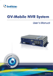
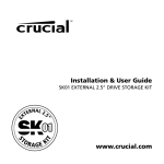
Quick Start Guide GV-Mobile NVR System The Vision of Security Thank you for purchasing GV-Mobile NVR System. This guide is designed to assist the new user in getting immediate results from the GV-Mobile NVR System. For advanced information on how to use the GV-Mobile NVR System, please refer to GV-Mobile NVR System User's Manual (GV-Desktop < Program button < User Manual). 2014/09 English MBNVR-QG-A © 2014 GeoVision, Inc. All rights reserved. Under the copyright laws, this manual may not be copied, in whole or in part, without the written consent of GeoVision. Every effort has been made to ensure that the information in this manual is accurate. GeoVision, Inc. makes no expressed or implied warranty of any kind and assumes no responsibility for errors or omissions. No liability is assumed for incidental or consequential damages arising from the use of the information or products contained herein. Features and specifications are subject to change without notice. GeoVision, Inc. 9F, No. 246, Sec. 1, Neihu Rd., Neihu District, Taipei, Taiwan Tel: +886-2-8797-8377 Fax: +886-2-8797-8335 http://www.geovision.com.tw Trademarks used in this manual: GeoVision, the GeoVision logo and GV series products are trademarks of GeoVision, Inc. Windows and Windows XP are registered trademarks of Microsoft Corporation. September 2014 1. Contents Introduction .......................................................................................... 1 1.1 Packing List............................................................................................................... 1 1.2 Software License....................................................................................................... 2 1.3 Recommended Hard Disks ....................................................................................... 2 1.4 Options...................................................................................................................... 3 1.5 Overview ................................................................................................................... 4 1.5.1 Front View...................................................................................................... 4 1.5.2 Rear View ...................................................................................................... 6 2. Getting Started....................................................................................... 8 2.1 Interface Connection................................................................................................. 8 2.2 Turning on and off the Power ...................................................................................10 2.3 Installing the Storage Drive ......................................................................................13 2.3.1 GV-MNVR1000 System.................................................................................13 2.3.2 GV-MNVR2100 System.................................................................................14 2.4 Formatting the Storage Drive ...................................................................................15 2.5 Configure the IP Address .........................................................................................18 2.6 Exiting to Windows ...................................................................................................21 3. Accessing GV-Mobile NVR System ........................................................... 22 3.1 Main Screen .............................................................................................................22 3.1 1 Adding a Storage Drive to the Recording Path ..............................................23 3.1.2 Adding IP Cameras .......................................................................................24 3.1.3 Renaming the Camera ..................................................................................26 3.1.4 Choosing Recording Mode............................................................................26 3.2 Setting up a Recording Schedule .............................................................................27 3.3 Playing Back Video...................................................................................................28 3.3.1 Playback Controls .........................................................................................29 3.4 Backing Up Video Files ............................................................................................29 3.4.1 Playing Backup Files.....................................................................................31 4. System Restoration .............................................................................. 32 1. Introduction Welcome to the GV-Mobile NVR System Quick Start Guide. In this quick guide, you will find information on the basic installation and configurations of the GV-Mobile NVR System. For detailed information, see GV-Mobile NVR System User’s Manual (GV-Desktop < Program button < User Manual). 1.1 Packing List 1. GV-Mobile NVR System 2. 3-pin Terminal Block (for ACC Connection and DC In) 3. HDD screw x 4 (for GV-MNVR1000 System) 4. HDD screw x 8 (for GV-MNVR2100 System) 5. GPS Antenna 6. GV-NVR Dongle for third-party IP Camera Connection (Optional) 7. DVD (User’s Manual and Quick Start Guide included) 1 1.2 Software License Free License 24 / 32 channels from GV-IP Devices Maximum License 24 / 32 channels from third-party IP devices Increment for Each License Optional Combination Dongle Type 1.3 1 to 24 / 32 third-party IP cameras at an increment of 2 N/A External Recommended Hard Disks GV-Mobile NVR supports up to 2 SATA HDD / SSD (2.5”) with up to 2 TB capacities. For the optimal system performance, it is recommended to use the SSD (MLC or SLC) or the enterprise-level HDD, such as HGST Endurastar series and Toshiba automotive HDD. 2 1.4 Options Optional devices can expand your GV-Mobile NVR System’s capabilities and versatility. Contact your dealer for more information. GV-IO Box 4 provides 4 inputs and 4 relay outputs, and supports GV-IO Box (4 Ports) both DC and AC output voltages. A USB port is provided for PC connection. GV-IO Box 8 provides 8 inputs and 8 relay outputs, and supports GV-IO Box (8 Ports) both DC and AC output voltages. A USB port is provided for PC connection. GV-IO Box 16 provides 16 inputs and 16 relay outputs, and GV-IO Box (16 Ports) supports both DC and AC output voltages. A USB port is provided for PC connection. GV-Joystick V2 facilitates the PTZ camera control. It can be GV-Joystick V2 either plugged into the GV-Mobile NVR System for independent use or connected to GV-Keyboard V3 to empower the operation. The GV-Keyboard V3 is designed to program and operate the GV-Keyboard V3 system, and it can also be connected with PTZ cameras directly for PTZ control. GV-IR Remote Controls GV-Mobile NVR System with the Remote Control. Control The GV-TouchDisplay133 is a touch panel designed for GV-TouchDisplay133 GV-Mobile NVR System. With the touch panel, you can monitor live images and operate its OSD functions. Power Adapter Power adapters are available in 4 regions: U.S.A., Australia, U.K and Europe. The 3G or 4G module allows data exchange for the GV-Mobile 3G / 4G Module NVR through the network connection covering wide area. It also empowers the application of GPS for the data transmission to the GV-GIS for real-time vehicle tracking. WiFi Module The WiFi module allows data exchange for the GV-Mobile NVR through wireless network connection within local area. Note: The WiFi / 3G / 4G module will be built in the GV-Mobile NVR System and tested before shipment. Opening the case and installing the accessories yourself will void the warranty. 3 1.5 Overview 1.5.1 Front View GV-MNVR1000 System 2 1 3 11 11 13 12 4 5 7 6 11 11 5 6 8 9 8 9 10 GV-MNVR2100 System 1 11 2 3 13 12 10 4 11 4 7 14 10 11 No. Name No. Name 1 Event Button (Not Functional) 8 Audio Line Out Port 2 HDD Status LED 9 Audio Microphone In Port 3 WWAN LED 10 2.5” HDD/SSD Slot 4 USB 3.0 Port 11 Antenna Port 5 Reset Button 12 WLAN LED 6 SIM Card Slot 13 Power Status LED 7 CFast Card Slot 14 USB 2.0 Port Note: The WLAN WiFi and WWAN 3G / 4G module is optional. Status Indicator LEDs HDD LED WWAN LED WLAN LED Power LED Indicator LED Color Description HDD LED Orange Glows when HDD/SSD is active. WWAN LED Orange Glows when WWAN is active. WLAN LED Orange Glows when WLAN is active. Power LED Green Glows when power is turned on. 5 1.5.2 Rear View GV-MNVR1000 System 1 2 12 3 5 4 11 6 7 10 8 9 No. Name No. Name 1 Audio Microphone In Port 7 DC Power Output (Not Functional) 2 Gigabit Ethernet Port x 2 8 DC 10 V - 35 V Power Input 3 VGA Output 9 GPS Antenna Port 4 USB 2.0 Port x 2 10 MCU DIO Port (Not Functional) 5 GPIO Terminal Block (Not Functional) 11 COM Port x 3 6 DisplayPort Output 12 Audio Line Out Port 6 GV-MNVR2100 System 1 2 3 12 15 14 4 13 12 5 10 6 7 12 10 8 11 9 10 No. Name No. Name 1 Gigabit Ethernet Port x 2 9 DC 10 V - 35 V Power Input 2 Audio Microphone In Port 10 Antenna Port x 3 3 USB 3.0 Port 11 MCU DIO Port (Not Functional) 4 DisplayPort Output 12 COM Port x 3 5 VGA Output 13 USB 2.0 Port 6 GPIO Terminal Block (Not Functional) 14 GPS Antenna Port 7 DC Power Output (Not Functional) 15 Audio Line Out Port 8 Fuse (15A) 7 2. Getting Started 2.1 Interface Connection This section describes the equipments required to operate the GV-Mobile NVR System. Here we use the GV-MNVR2100 System for example. 2 3 1 4 Rear Side 5 6 7 HDD/SSD x 2 Front Side 1. There are two options for connecting the power. A. Connect the GV-Mobile NVR System to the vehicle’s power battery and ACC wire using the supplied 3-pin terminal block. The system will automatically start after you turn on the vehicle ignition. Power is supplied to the system as long as the vehicle ignition is on. Ground Power Ignition 8 B. Optionally purchase a power adapter from GeoVision. See 2.2 Turning on and off the Power. 2. Use the VGA cable or the DisplayPort cable to connect the unit to the monitor. Note: The GV-Mobile NVR System supports dual-monitor display. You can connect two monitors by using the VGA connector and DisplayPort. 3. Connect one end to the Gigabit Ethernet port and the other end to Network by using the RJ-45 cable. 4. Connect the keyboard and the mouse to the USB ports. 5. Connect the speaker to the Audio Line Out port. 6. Optionally connect the microphone to the Audio Microphone In port for two-way audio with IP cameras. 7. Insert the 2.5” HDDs or SSDs into the storage slots. For details, see 2.3 Installing the Storage Drive. After the unit is powered on, the Power Indicator LED shows constant green. Before recording, you need to format the storage drive and add it to the recording path of the system. For formatting the storage drive, see 2.4 Formatting the Storage Drive. For adding the storage drive to the recording path, see 3.1.1 Adding the Storage Drive to the Recording Path. 9 2.2 Turning on and off the Power The GV-Mobile NVR System is designed to connect to the vehicle’s ACC wire. However, you can optionally purchase a power adapter (AC 100 ~ 240 V) from GeoVision for power connection. 2.2.1 Connecting to the ACC Wire To turn on the GV-Mobile NVR System, connect the vehicle’s ACC and power wires to the unit’s power input using the supplied 3-pin terminal block. The system will automatically start after you power on the vehicle for 5 seconds. After you power off the vehicle for 3 seconds, the system will turn off automatically. 2.2.2 Using the Power Adapter To turn on and off the GV-Mobile NVR System using an optional power adapter from GeoVision, follow the steps below. 1. Plug the 3-pin terminal block connected with power adapter to the panel’s power pins. The GV-Mobile NVR System will be powered on about 5 seconds later. 2. To turn off the GV-Mobile NVR System, shut down the system through the Windows desktop. 10 Using Rocker Switch to Simulate ACC Ignition For quick control of turning on or off the GV-Mobile NVR System, you can install a rocker switch to the 3-pin terminal block with the optional power adapter. For the connection and operation, follow the steps below. Rocker Switch 1. For the 3-pin terminal block with optional power adapter, unplug the U-shaped wire from the Power and Ignition pins. Power Ground Ignition U-Shaped Wire 2. Connect the wires of the rocker switch to the Power and Ignition pins respectively. 3. Plug the terminal block to the panel’s power pins. 11 4. Press the rocker switch to turn on the GV-Mobile NVR System without operating on the Windows desktop. Once the rocker switch is on, the GV-Mobile NVR System will be powered on about 3 seconds later. 5. To turn off the GV-Mobile NVR System, press the rocker switch again. Note: After the power is on, the GV-Mobile NVR System will run a series of self-tests, and a series of messages may be displayed as the various hardware and software subsystems are activated. After the process is finished, the GV-System Software (Multicam Surveillance System) should load automatically and bring you to the main screen. 12 2.3 Installing the Storage Drive The GV-Mobile NVR System uses SATA hard drive / SSD for video data storage. Before recording, be sure to install the storage drive. 2.3.1 GV-MNVR1000 System 1. Loosen the thumb screws on the HDD/SSD slot and pull out the drive drawer. 2. Insert the storage drive into the drive drawer with the SATA data and power connector facing towards the end. Power Connector 3. Secure the storage drive with the drive drawer using the supplied 4 screws. Note: For convenience, it is suggested to secure the screws with the drive drawer being placed downward. 4. Insert the drive drawer into the HDD/SSD slot and secure the thumb screws. 13 2.3.2 GV-MNVR2100 System 1. Loosen the thumb screws on the HDD/SSD slots and remove the covers. 2. Press the release latch and pull out the drive drawer using the drawer handle that pops out. Release Latch 3. Insert the storage drive into the drive drawer with the SATA data and power connector facing towards the end. Power Connector 4. Secure the storage drive with the drive drawer using the supplied 4 screws. 5. Insert the drive drawer into the HDD/SSD slot, put the drawer handle back and rotate the release latch until it is vertical to lock the drive drawer. 6. Put the cover back and secure the thumb screw. 7. Repeat the steps above to install the storage drive in the other HDD/SSD slot. The HDD Status LED glows, and the storage drive is ready for use. 14 2.4 Formatting the Storage Drive After installing HDD / SSD to your system, you will need to format the storage drive before recording. 1. On the GV-Desktop, click the Programs button, and select Disk Management. 2. Type the ID and password in the dialog box. The default ID and password are “0000”. 3. Right-click in the unallocated space of a new drive, and select New Simple Volume. 4. In the appeared New Simple Volume Wizard dialog box, click Next to continue. 15 5. The default partition size is the same as the maximum disk space. Make changes if necessary and click Next to continue. 6. Assign a drive path that is not in use by other devices and click Next to continue. 16 7. Type a name in the Volume label box, ex. HDD1, and click Next to continue. 8. When the formatting is complete, click Finish to close the wizard. 17 2.5 Configure the IP Address GV-Mobile NVR System supports remote monitoring, control and configuration over a network connection. The following default IP addresses will automatically be assigned. Connection 1: 192.168.0.200 Connection 2: 192.168.0.201 Default Subnet Mask: 255.255.252.0 The local area connections listed correspond to the Ethernet ports as shown below: Local Area Connection 1 Default IP: 192.168.0.200 Local Area Connection 2 Default IP: 192.168.0.201 To change the above default IP addresses, follow the steps below. 1. On the GV-Desktop, click the Programs button, and select Control Panel. 2. Type the ID and password. The default ID and password are “0000”. The Control Panel window appears. 18 3. Under Network and Internet, click View network status and tasks. 4. Under Connections, select the Local Area Connection you want to configure. 5. Select Internet Protocol Version 4 (TCP/IPv4), and select Properties. 19 6. Select Use the following IP address and type the new IP information in the fields. Or select Obtain an IP address automatically to enable dynamic IP address. 7. Click OK to finish the setting. 20 2.6 Exiting to Windows The unit is protected by GV-Desktop that is limited to run the selected programs. If you need to exit to Windows desktop, follow the steps below. 1. On the GV-Desktop, click the Settings button, and type the valid ID and password. The default ID and Password are “0000”. The Settings dialog box appears. 2. Under Desktop Type, select Windows from the drop-down list, and click OK. 3. Click the Log Off button, and type the ID and Password to display the Windows desktop. 1 2 3 21 3. Accessing GV-Mobile NVR System 3.1 Main Screen 10 11 12 13 14 1 2 3 4 5 6 7 8 9 1. Logout / Exit / Minimize 8. Start/stop screen rotation 2. Select screen divisions 9. Access remote applications 3. Select a camera for full screen mode 10. Camera Name 4. Start/stop recording 11. Date / Time / Storage Space 5. Set up recording schedules 12. Status indicators for remote applications 6. Access system settings 13. Click to call up PTZ Control Panel 7. Access ViewLog to play back video 14. Click to call up I/O Control Panel 22 3.1 1 Adding a Storage Drive to the Recording Path Before recording, you need to add the formatted storage drive to the recording path. 1. On the GV-Desktop, click the Programs button and select Hot Swap HDD Tool. 2. If a storage drive is already inserted, right-click it in the MediaMan Tools window, select Add for recording and select the storage group from the drop-down list. 3. If a storage drive is not inserted, follow the steps below. A. Insert a HDD / SSD to the GV-Mobile NVR System. This dialog box appears. B. Click Add to recording path and select the storage group from the drop-down list. 4. Click OK to automatically configure the storage drive to the recording path. 5. In the MediaMan Tools window, if a storage drive is successfully added to store data, its Status field should display “Standby”. Status field 6. To add another formatted storage drive, repeat the above steps. 23 3.1.2 Adding IP Cameras The following instructions are the setup procedure for adding an IP camera in the system. 1. On the main screen, click the Configure button IP Camera Install. , select System Configure and click 2. To automatically add an IP camera on the LAN, click Scan Camera. To manually set up an IP camera, click Add Camera and follow the steps below. 3. Type the IP address, username and password of the IP camera. Keep the default HTTP port 80 or modify if necessary. 4. Select a camera brand and model from the Brand and Device drop-down lists respectively. This dialog box appears. 5. The options in the dialog box may vary depending on camera brands. 24 Dual Streams: Click the button to apply the default codec and resolution of the GV-IP camera. Query: Use the current codec and resolution setting on the GV-IP camera. Camera list: Select a camera number. Port: Keep or modify the default video streaming port 10000. Stream Type: You may have the option of single or dual streaming depending on camera models. Codec Type: You may have different codec options depending on camera models. If the selected camera supports dual streaming, the preview codec and recording codec can be set differently. Resolution: Select the resolutions for preview and recording. 6. Click Apply. The IP camera is added to the list. 7. Right-click the camera and select Display position to map the camera to a channel. 8. The Status column now should display “Connected”. Click OK. 25 3.1.3 Renaming the Camera 1. Click on the main screen, click System Configure and select Camera Configure. 2. In the Camera Name field, type a new name for the camera. 3. Click OK. 3.1.4 Choosing Recording Mode You can set each camera's recording mode individually for Motion Detection, Round-the-Clock or Day-Night. 1. Click on the main screen, click System Configure and select Camera Configure. 2. From the Camera Name drop-down list, select one camera. 3. In the Rec Control field, click Rec Video and use the drop-down list to select Motion Detect, Round-the-Clock or Day-Night. 4. If you select Day-Night, click the Arrow button after the Rec Video option to set up time frames. 5. Click OK. For details on setting camera properties, refer to Adjusting Individual Camera, Chapter 1, DVR User’s Manual (GV-Desktop < Program button < User Manual). 26 3.2 Setting up a Recording Schedule You can program recording to turn on and off at a specific time each day. 1. Click on the main screen, and select Schedule Edit. 2. Select or enter the Start and End time of the schedule. 3. Select day(s). 4. Select Rec and use the drop-down list to select Round-the-Clock or Motion Detect for recording mode. 5. Select camera(s). 6. Click Add Schedule. 7. Click OK. For details, refer to Recording Schedule, Chapter 1, DVR User's Manual (GV-Desktop < Program button < User Manual). 4 2 5 3 6 7 27 3.3 Playing Back Video You can play back video recorded during a particular date and time. 1. Click on the main screen, and select Video/Audio Log. 2. Select the camera you wish to view. 3. Select a date folder from the date tree. 4. Select a time from the Video Events list. 5. Click to begin playback. For details, refer to Playing Back on ViewLog, Chapter 4, DVR User's Manual (GV-Desktop < Program button < User Manual). 4 28 3.3.1 Playback Controls 12 1 No. 2 3 13 4 5 Description 6 7 8 9 10 No. 11 Description 1 Rewind to Beginning 8 Speed up/down 2 Frame-by-Frame Reverse 9 Zoom in/out 3 Rewind 10 A to B Playback 4 Stop 11 Frame-by-Frame / Real Time Playback 5 Play 12 Playback Scroll 6 Frame-by-Frame Forward 13 Audio on/off 7 Forward to End Using the Zoom Zoom in: Click the Zoom-in button, and then click on the area you want to magnify. Each click will increase the zoom level. Zoom out: Click the Zoom-out button, and then click on the image to zoom out. Each click will decrease the zoom level. 3.4 Backing Up Video Files You can back up video files of the desired time to CD / DVD. 1. Insert the CD / DVD media into the drive. 2. Click on the main screen, and select Video/Audio Log. 3. Click on the functional panel. 4. Select CD Using OS-Burning to burn files with the inbuilt software of Windows. 5. Click Add time frame. 29 6. Enter the Start Time and End Time for backup. 7. Select the desired camera(s) for backup. The number of video and audio files of each camera is indicated respectively, e.g. “Camera 3 39+0” means the camera 3 has 39 video files and 0 audio file. 8. Select the types of events for backup, e.g. video, audio or both together. 9. Click OK to add the time frame. You can repeat steps 5-8 to create up to 10 time frames. 10. Click OK to start burning. For details, refer to Backing Up Video Files Using ViewLog, Chapter 5, DVR User's Manual (GV-Desktop < Program button < User Manual). 6 4 5 10 9 30 3.4.1 Playing Backup Files Open the backup folder, run EZViewLog500.exe, and then follow the instructions in the Play Back Video section. 31 4. System Restoration You can restore preinstalled files once they are damaged by running the recovery from the hidden partition. To restore the operating system and all preinstalled software, follow the steps below. Note: After recovery, you need to re-install all settings and passwords. But the recovery will not delete your recording files saved on the GV-Mobile NVR System since it only reformats the partition C and all of your files are still stored on other partitions. 1. On the GV-Desktop, click the Program button and select Recovery. The system will run this command by itself. 2. Restart the GV-Mobile NVR System. 3. Press F11 button several times to avoid accessing the system. 4. When the below screen appears, press the Recovery button. 5. When the restoring process is completed, the screen will automatically show the GV-Desktop, and the system will restore the default values. 32