1
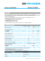
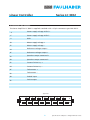
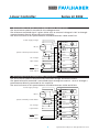
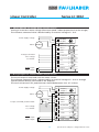
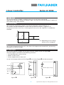
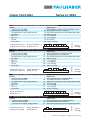
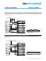
Linear Controller
4-Quadrant for DC-Micromotors
Operating Instructions
Series LC 3002
Operating Instructions
c om
w. fau
w
w
l
h
er.
b
a
Miniature Drive Systems
Micro Drives
DC-Micromotors
Precision Gearheads
Servo Components
Drive Electronics
Surf to the following Internet
address and you will find the
latest edition of the instruction
manual on-line:
www.minimotor.ch/uk/pr/
For direct Download:
http://www.minimotor.ch/minicatalog/pdf/DriveCircuits/Manuals/IM_e_LC_3002.pdf
Linear Controller
Series LC 3002
Index
1. Description
2. Technical specifications
3. Dimensions and weight
Page
1
1
1
4. Connector / Pin location
2
5. Wiring diagram for Motor-Tacho Feedback control (Speed control)
6. Wiring diagram for IR Compensation (Speed control)
3
3
7. Wiring diagram for Voltage drive (Voltage control)
8. Wiring diagram for Current control (Torque control)
4
4
9.
10.
11.
12.
Enable input
Current limiter
Excess temperature protection
Fault output
13. DIP Switch settings for various operating modes
14. On-board trimmers and LEDs
5
5
5
5
6
6
15.
16.
17.
18.
19.
20.
RPM setting
I-max setting
I-dyn setting
XP setting
IR setting
Offset setting
7
7
7
7
7
7
21.
22.
23.
24.
Checklist
Checklist
Checklist
Checklist
8
8
8
8
for Motor-Tacho Feedback control (Speed control)
for IR Compensation (Speed control)
for Voltage drive (Voltage control)
for Current control (Torque control)
25. Trimmer settings
26. Connection example for Motor-Tacho Feedback control (Speed control), 24 V DC supply
9
9
27. Connection example for Motor-Tacho Feedback control (Speed control), 22 V AC supply
28. Connection example for IR Compensation (Speed control)
10
10
29. Connection example for Voltage drive (Voltage cotrol)
30. Connection example for Current control (Torque control)
11
11
31. Trouble shooting
12
CAUTION:
Use the Servo Amplifier only in accordance with the set-up checklists on page 8.
Linear Controller
Series LC 3002
1. Description
The linear 4-quadrant Servo Amplifier LC 3002 is designed for use with highly dynamic brush
commutated DC-Micromotors which feature ironless rotors (System Faulhaber®).
The linear design assures that no electromagnetic radiation is generated and eliminates the
need for motor inductors.
The Servo Amplifier LC 3002 can be used in a variety of configurations such as:
• Motor-Tacho Feedback control (Speed control)
• IR Compensation control (Speed control)
• Voltage drive (Voltage control)
• Current control (Torque control)
The Servo Amplifier can be used either with DC or AC supply voltage.
2. Technical specifications
Minimum Typical
1)
Maximum
Unit
40 2)
W
–
20
Power supply voltage:
– DC supply
– AC supply
12
10
–
–
32
22
V DC
V AC
Motor supply voltage
–
–
26
V DC
Output current max.
–
2
–
A
Tachogenerator voltage
–
–
50
V
Reference voltage
–
±3 3)
–
V
Command voltage
–
±10
–
V
External command voltage I-dyn
–
0–10
–
V
Nominal power
24 V DC – 20 mA max.
Fault output (open collector)
Temperature range:
–operation
–storage
0
–20
–
–
+70 4)
+80
˚C
˚C
1)
2)
3)
4)
Maximum power which can be dissipated by the Servo Amplifier
With additional heat sink
Supply voltage for externally set potentiometer
Derating at higher temperature to be taken in consideration
3. Dimensions and weight
Size (Euro format)
100 x 160 mm
Width
6 TE (30,48 mm)
Weight
300 g
1
Specifications subject to change without notice
Linear Controller
Series LC 3002
4. Connector / Pin location
The Servo Amplifier LC 3002 is supplied standard with a 15-pin connector type DIN 41612.
4
Power supply voltage AC/DC +
6
Power supply voltage AC/DC –
8
GND
10
Motor supply voltage +
12
Motor supply voltage –
14
Reference voltage output –
16
Reference voltage output +
18
Speed or torque command +
20
Speed or torque command –
22
Current limiter Idyn +
24
Current limiter Idyn –
26
Tachometer +
28
Tachometer –
30
Enable input
32
Fault output
Type H15
6
10
14
18
22
26
30
Z
d
4
8
12
16
20
24
28
32
2
Specifications subject to change without notice
Linear Controller
Series LC 3002
5. Wiring diagram for Motor-Tacho feedback control (Speed control)
The actual motor speed is sensed with the tachogenerator.
The reference command signal is given either with an external voltage of ±10 V or through
a potentiometer directly connected to the amplifier.
The total resistance of this potentiometer should be between 10 kΩ and 47 kΩ.
Power supply voltage
Motor
DC-Motor
Speed command potentiometer
4
AC (DC+)
6
AC (DC –)
8
GND
10
12
Motor +
Motor –
14
Vref –
16
Vref +
18
ext. voltage
20
22
I-dyn limiter
24
Tacho
26
Tacho
28
Enable input
30
Fault output
32
Command
I-dyn
Tacho
DC
DC
–
+
+
–
+
–
Enable
Fault output
6. Wiring Diagram for IR Compensation (Speed control)
The actual motor speed is determined by the motor voltage and motor current.
The speed reference command is connected either through an external ±10 V or through a
potentiometer directly connected to the amplifier.
The total resistance of this potentiometer should be between 10 kΩ and 47 KΩ.
Power supply voltage
Motor
DC-Motor
Speed command potentiometer
4
AC (DC+)
6
AC (DC–)
8
GND
10
12
Motor +
Motor –
14
Vref –
16
Vref +
18
ext. voltage
Command
20
22
I-dyn limiter
24
26
28
Enable input
30
Fault output
32
3
I-dyn
Tacho
DC
DC
–
+
+
–
+
–
Enable
Fault output
Specifications subject to change without notice
Linear Controller
Series LC 3002
7. Wiring diagram for Voltage drive (Voltage control)
Setting of a constant motor voltage (the motor speed is about proportional to the voltage).
The reference command value is determined by an external voltage of ± 10 V.
Power supply voltage
Motor
DC-Motor
4
AC (DC+)
6
AC (DC–)
8
GND
10
12
Motor +
Motor –
14
Vref –
16
Vref +
Voltage command
Ext. voltage
18
I-dyn Limiter
22
Command
20
I-dyn
24
26
Tacho
28
Enable input
Fault output
30
Enable
32
Fault output
DC
DC
–
+
+
–
+
–
8. Wiring diagram for Current control (Torque control)
The actual torque is measured with the motor current.
The reference command value is determined by an external voltage of ± 10 V or through
a potentiometer directly connected to the amplifier.
The total resistance of this potentiometer should be between 10 K - 47 K Ohms.
Power supply voltage
Motor
DC-Motor
Torque command potentiometer
4
AC (DC+)
6
AC (DC–)
8
GND
10
12
Motor +
Motor –
14
Vref –
16
Vref +
18
Command
20
Ext. voltage
I-dyn Limiter
22
24
26
I-dyn
Tacho
28
Enable input
Fault output
4
DC
DC
–
+
+
–
+
–
30
Enable
32
Fault output
Specifications subject to change without notice
Linear Controller
Series LC 3002
9. Enable input
The Servo Amplifier LC 3002 is enabled when pins 8 and 30 are connected.
Opening this connection disables the power stage. This input must be connected via a potentialfree contact (e.g.: relay contact).
10. Current limiter
I-dyn
I-max
I-motor
The maximum continuous current is set with the dynamic current limiter (I-dyn).
This current can be exceeded for a short time up to the set value I-max (typical 2 A).
In the event of short circuit (i.e., current greater than 3,5 A) the amplifier is immediately
disabled.
∆t = depending on the charge
process of an integrator.
∆t
11. Excess temperature protection
The system automatically shuts off if the heat sink temperature exceeds 80˚C, preventing
damage of the power bridge.
12. Fault output
The Servo Amplifier LC 3002 uses an open collector output on pin 32 (Figure
The fault output is activated in the following situations:
➊ ).
• Activated dynamic current limiter
• Motor in short circuit
• Excess temperature on heat sink
At the Fault Output either an LED (Figure ➋) or a relay (Figure ➌) can be connected.
–
+
AC (DC+)
4
AC (DC+)
6
max.
24 V DC
8
Rv
32
+
–
External supply voltage
Fault output
10 m A
32
GND
8
20 m A
Figure
➊
Figure
5
32
➋
8
Figure ➌
Specifications subject to change without notice
Linear Controller
Series LC 3002
13. DIP Switch settings for various operating modes
Operating mode / DIP Switches
1
2
3
4
Motor-Tacho regulation (Speed control)
on
A
IR regulation (Speed control)
on
A
Voltage drive regulation (Voltage control)
on
Current control regulation (Torque control)
on
5
on
6
7
8
on
on
on
9
0
B
on
on
B
on
on
B
A
B
A. DIP Switch 4
This switch should be off if the command signal comes from a potentiometer connected
to the V-ref terminals. This switch should be on if an external voltage is used.
B. DIP Switch 0
This switch should be on when the dynamic current limit I-dyn is set using the on-board trimmer.
This switch should be off if the dynamic current limit I-dyn is externally set.
14. On-board trimmers and LEDs
The on-board trimmers have a twenty (20) turn range. Before operating the amplifier the
trimmers have to be set according to the following table.
Position
Function
RPM
CCW
Min. speed
Speed selection
IR
CCW
Min. stiffness
IR compensation
Max. continuous current
Continuous current
I-dyn
Offset
XP
I-max
CW
Middle
CCW
CW
LED1
Zero output balance
Min. stiffness
Amplification control
Max. intermittent current
Short duration current
Power
Power supply indicator
Green
>
I-max
On if I-max is exceeded
Red
LED3
>
T-max
On if excess temperature
Red
▼ ▼ ▼
▼
▲
▼ ▼
red
Note:
In different operating modes not all
trimmers will be used.
Unused trimmers should be set to the
positions given in the table.
red
green
RPM
IR
I-dyn
Offset
XP
I-max
Power
I-max
T-max
LED2
⊗ ⊗ ⊗
6
Specifications subject to change without notice
Linear Controller
Series LC 3002
15. RPM setting
Scope: The desired max. motor speed is set with the RPM trimmer.
Action: Input a reference command voltage or set a value via external potentiometer
according to the desired max. speed.
Turn the RPM trimmer CW until the motor reaches a speed corresponding to the
max. set value.
16. I-max setting
Scope: The desired max. peak current is set with the I-max trimmer.
Action: Use a digital amp. meter connected in series with motor. Stall the motor.
Turn the I-max trimmer CCW until the max. permissible current is reached.
Note: Make this adjustment as fast as possible, since the dynamic current limiter will be
activated after a short period of time.
17. I-dyn setting
Scope: The dynamic current limitation is set with the I-dyn trimmer.
Action: Use a digital amp. meter connected in series with motor. Stall the motor.
Turn the I-dyn trimmer CCW until the max. permissible continuous current is reached.
18. XP setting
Scope: The amplifier’s gain and therefore also its operating stability (stiffness) is set with
the XP trimmer.
Action: Run the motor at a low speed by input of a corresponding set value.
Turn the XP trimmer CW until the motor starts vibrating (swinging), then turn the
trimmer one full turn CCW.
19. IR setting
Scope: The amplifier’s gain and therefore also its operating stability (stiffness) is set with
the IR trimmer.
Action: Run the motor at a low speed by input of a corresponding set value.
Turn the IR trimmer CW until the motor starts vibrating (swinging), then turn the
trimmer one full turn CCW.
20. Offset setting
Scope: Zero speed or motor standstill between rotation directions is set with the offset
trimmer.
Action: Input 0 (zero) set value. Turn the offset trimmer CW or CCW until the motor shaft
does not turn.
7
Specifications subject to change without notice
Linear Controller
Series LC 3002
21. Checklist for Motor-Tacho Feedback control (Speed control)
Action
References
– Connect the LC 3002
5 Wiring diagram Motor-Tacho Feedback control
– Preset potentiometer
14 On-board trimmers and LEDs
– Set operation mode, apply power
13 DIP Switch settings for various operating modes
– Set RPM
15 RPM setting
– Set I-max
16 I-max setting
– Set I-dyn
17 I-dyn setting
– Set XP
18 XP setting
– Set offset
20 Offset setting
B (on) Trimmer I-dyn
B (off) ext. I-dyn
A
B
1 2 3 4 5 6 7 8 9 0
on
↔
A (off) Poti over V-ref
A (on) ext. set value
off
Switch
settings
22. Checklist for IR Compensation (Speed control)
Action
References
– Connect the LC 3002
6 Wiring diagram IR Compensation
– Preset potentiometer
14 On-board trimmers and LEDs
– Set operation mode, apply power
13 DIP Switch settings for various operating modes
– Set RPM
15 RPM setting
– Set I-max
16 I-max setting
– Set I-dyn
17 I-dyn setting
– Set IR
19 I x R setting
– Set offset
20 Offset setting
B (on) Trimmer I-dyn
B (off) ext. I-dyn
A
B
1 2 3 4 5 6 7 8 9 0
↔
on
A (off) Poti over V-ref
A (on) ext. set value
off
Switch
settings
23. Checklist for Voltage drive (Voltage control)
Action
References
– Connect the LC 3002
7 Wiring diagram for Voltage drive
– Preset potentiometer
14 On-board trimmers and LEDs
– Set operation mode, apply power
13 DIP Switch settings for various operating modes
– Set RPM
15 RPM setting
– Set I-max
16 I-max setting
– Set I-dyn
17 I-dyn setting
– Set offset
20 Offset setting
1 2 3 4 5 6 7 8 9 0
↔
on
B
B (on) Trimmer I-dyn
B (off) ext. I-dyn
off
Switch
settings
24. Checklist for Current control (Torque control)
Action
References
– Connect the LC 3002
8 Wiring diagram for Current control
– Preset potentiometer
14 On-board trimmers and LEDs
– Set operation mode, apply power
13 DIP Switch settings for various operating modes
B (on) Trimmer I-dyn
B (off) ext. I-dyn
A
B
1 2 3 4 5 6 7 8 9 0
8
on
↔
A (off) Poti over V-ref
A (on) ext. set value
off
Switch
settings
Specifications subject to change without notice
Linear Controller
Series LC 3002
▼ ▼ ▼
▼
▲
▼ ▼
red
red
green
RPM
IR
I-dyn
Offset
XP
I-max
Power
I-max
T-max
25. Trimmer settings
RPM CCW
Min. Speed
IR
CCW
Min. Stiffness
I-dyn
CW
Max. Continuous current
Offset Center
XP
CCW
Min. Stiffness
I-max CW
Max. Current
⊗ ⊗ ⊗
Note: Motor supply voltage selection
The voltage loss in the Servo Amplifier is 6 Volts. Therefore, the maximum possible motor
supply voltage is always 6 Volts less the power supply voltage of the amplifier.
26. Connection example for Motor-Tacho Feedback control (Speed control), 24 V DC supply
Common supply. Set value and I-dyn via PLC, PC, etc., without enable control and failure scan.
Power supply
24 V DC
LC 3002A
0-18V
M
PLC, PC…
D
A
D
±10V
A
0-10V
A GND
Digital Out
Digital In
+
T
AC (DC+)
6
AC (DC –)
8
GND
10
Motor +
12
Motor –
14
Vref –
16
Vref +
18
28
–
Command
+
+
I-dyn
–
+
Tacho
–
30
Enable
32
Fault output
20
22
24
26
DC
DC
on
1 2 3 4 5 6 7 8 9 0
↔
Power
supply
4
off
Switch settings
9
Specifications subject to change without notice
Linear Controller
Series LC 3002
27. Connection example for Motor-Tacho Feedback control (Speed control), 22 V AC supply
Separate AC supply for the LC 3002. Set value and I-dyn via PLC, PC, etc., with enable control
and failure scan.
Power supply
220 V AC
LC 3002A
22 V AC
Power
supply
0-24V
M
PLC, PC…
D
A
D
±10V
A
0-10V
A GND
Digital Out
+
Digital In
T
4
AC (DC+)
6
AC (DC –)
8
GND
10
Motor +
12
Motor –
14
Vref –
16
Vref +
18
28
–
Command
+
+
I-dyn
–
+
Tacho
–
30
Enable
32
Fault output
20
22
24
26
DC
DC
on
1 2 3 4 5 6 7 8 9 0
↔
24 V DC
off
Switch settings
28. Connection example for IR Compensation (Speed control)
Common supply. Set values RPM and I-dyn via PLC, PC, etc., without enable control and
failure scan.
Power supply
24 V DC
LC 3002A
0-18V
M
PLC, PC…
D
A
D
±10V
A
0-10V
A GND
Digital Out
4
AC (DC+)
6
AC (DC –)
8
GND
10
Motor +
12
Motor –
14
Vref –
16
Vref +
18
28
–
Command
+
+
I-dyn
–
+
Tacho
–
30
Enable
32
Fault output
20
22
24
26
Digital In
+
DC
DC
on
1 2 3 4 5 6 7 8 9 0
↔
Power
supply
off
Switch settings
10
Specifications subject to change without notice
Linear Controller
Series LC 3002
29. Connection example for Voltage amplifier (Power amplifier)
Common supply. Set value and I-dyn setting via PLC, PC, etc. Enable control via PLC, without
failure scan.
Power supply
24 V DC
Power
supply
0-18V
D
M
A
D
±10V
A
0-10V
A GND
Digital Out
AC (DC+)
6
AC (DC –)
8
GND
10
Motor +
12
Motor –
14
Vref –
16
Vref +
18
28
–
Command
+
+
I-dyn
–
+
Tacho
–
30
Enable
32
Fault output
20
22
24
26
+
Digital In
DC
DC
on
1 2 3 4 5 6 7 8 9 0
↔
PLC, PC…
LC 3002A
4
off
Switch settings
30. Connection example for Current control (Torque control)
Common supply. Set value for torque and I-dyn via PLC, PC, etc., without enable control
and failure scan.
Power supply
24 V DC
LC 3002A
0-18V
M
PLC, PC…
D
A
D
±10V
A
0-10V
A GND
Digital Out
4
AC (DC+)
6
AC (DC –)
8
GND
10
Motor +
12
Motor –
14
Vref –
16
Vref +
18
28
–
Command
+
+
I-dyn
–
+
Tacho
–
30
Enable
32
Fault output
20
22
24
26
Digital In
+
DC
DC
on
1 2 3 4 5 6 7 8 9 0
↔
Power
supply
off
Switch settings
11
Specifications subject to change without notice
Linear Controller
Series LC 3002
31. Trouble shooting
If difficulties are experienced, please check the following points:
●
Check connections:
Are motor leads reversed?
Are tacho leads reversed?
Is Enable (pin 30) connected to GND (pin 8)?
●
Check DIP switch settings.
●
Follow the checklists, in proper order (page 8).
●
Always be sure that the potentiometers are in their starting positions.
12
Specifications subject to change without notice
The FAULHABER Group:
DR. FRITZ FAULHABER
GMBH & CO. KG
Daimlerstraße 23
71101 Schönaich · Germany
Tel.: +49 (0)7031/638-0
Fax: +49 (0)7031/638-100
Email: [email protected]
www.faulhaber.de
MINIMOTOR SA
6980 Croglio · Switzerland
Tel.: +41 (0)91 611 31 00
Fax: +41 (0)91 611 31 10
Email: [email protected]
www.minimotor.ch
MicroMo Electronics, Inc.
14881 Evergreen Avenue
Clearwater · FL 33762-3008 · USA
Phone: +1 (727) 572-0131
Fax: +1 (727) 573-5918
Toll-Free: (800) 807-9166
Email: [email protected]
www.micromo.com
©MINIMOTOR SA
Edition 15.09.2000


![Final Report - [Almost] Daily Photos](http://vs1.manualzilla.com/store/data/005658230_1-ad9be13b69bd4f2e15f58148160b0f22-150x150.png)