1
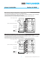
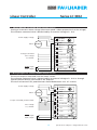
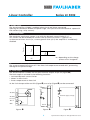
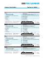
Linear Controller
Series LC 3002
7. Wiring diagram for Voltage drive (Voltage control)
Setting of a constant motor voltage (the motor speed is about proportional to the voltage).
The reference command value is determined by an external voltage of ± 10 V.
Power supply voltage
Motor
DC-Motor
4
AC (DC+)
6
AC (DC–)
8
GND
10
12
Motor +
Motor –
14
Vref –
16
Vref +
Voltage command
Ext. voltage
18
I-dyn Limiter
22
Command
20
I-dyn
24
26
Tacho
28
Enable input
Fault output
30
Enable
32
Fault output
DC
DC
–
+
+
–
+
–
8. Wiring diagram for Current control (Torque control)
The actual torque is measured with the motor current.
The reference command value is determined by an external voltage of ± 10 V or through
a potentiometer directly connected to the amplifier.
The total resistance of this potentiometer should be between 10 K - 47 K Ohms.
Power supply voltage
Motor
DC-Motor
Torque command potentiometer
4
AC (DC+)
6
AC (DC–)
8
GND
10
12
Motor +
Motor –
14
Vref –
16
Vref +
18
Command
20
Ext. voltage
I-dyn Limiter
22
24
26
I-dyn
Tacho
28
Enable input
Fault output
4
DC
DC
–
+
+
–
+
–
30
Enable
32
Fault output
Specifications subject to change without notice


![Final Report - [Almost] Daily Photos](http://vs1.manualzilla.com/store/data/005658230_1-ad9be13b69bd4f2e15f58148160b0f22-150x150.png)