1
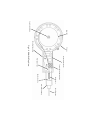
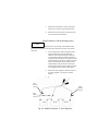
2-3-4. Tension roller pressure setting.
NOTE
The tension roller pressure is set at the factory to accommodate .035”
(0.9mm) flux cored wire.
a.
Set the tension roller pressure as light as possible to maintain a
continuous feed while minimizing wire distortion.
b.
The knurled adjusting knob rotates counterclockwise to reduce
pressure and clockwise to increase pressure.
c.
With the wire loaded and the power cables attached point the
welder at a non-conductive hard object (a concrete floor or wall for
example) with the contact tip approximately two inches from the
surface.
d.
Depress the trigger causing wire to beginning spooling out at low
speed, approximately 100 inches (250cm) per minute. As the wire
hits the surface it should be turned aside, coiling the wire.
e.
Slowly turn the adjusting knob counterclockwise until the wire
begins to slip in the rollers. Remove pressure from the trigger to
shut down the drive system.
f.
Turn the adjusting knob ½ turn clockwise.
g.
Test to ensure there is no longer any slippage by again depressing
the trigger and observing the wire and spool.
2-4. CABLE CONNECTIONS
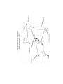
2-4-1. Harness to power source.
WARNING
Never allow the GOWELD to unintentionally contact any part of the
workpiece or other surface that may be grounded into the welder circuit as
electric shock may occur. Once the GOWELD has been attached to the