1
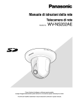
PC Software Package
Operating Instructions
Model No.
WV-AS710
Before attempting to connect or operate this product,
please read these instructions carefully and save this manual for future use.
CONTENTS
FEATURES ..................................................................................................................... 4
Operation ......................................................................................................................... 10
How to Use the "TOP MENU" .................................................................................... 12
How to Use the Camera Page .................................................................................... 13
Camera Selection Menu ............................................................................................. 14
Picture Display Area ................................................................................................... 15
Live Mode Panel ......................................................................................................... 17
Playback of Recorded Pictures .................................................................................. 20
Searching Menu ......................................................................................................... 23
Play Mode Panel ........................................................................................................ 27
Quad Screen .............................................................................................................. 29
Installation of the MPEG-4 Plug-in Software .............................................................. 30
Installation of the MPEG-4 Player .............................................................................. 31
Installation ....................................................................................................................... 32
Procedures to Establish the Network Camera Server ................................................ 32
Selection of the System Type ..................................................................................... 33
Confirmation of the Directory Structure ...................................................................... 34
Installation of Red Hat Linux ...................................................................................... 35
Allocation of Disk Space (When "Live View & Recording" is Selected) ..................... 36
How to Allocate Disk Space ....................................................................................... 37
Installation of the WV-AS710 ..................................................................................... 38
Starting up the Network Camera Server .................................................................... 39
After the Installation of the WV-AS710 ....................................................................... 41
Stop the WV-AS710 ................................................................................................... 41
Uninstallation .............................................................................................................. 42
Administration .................................................................................................................. 43
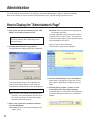
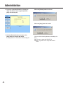
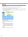
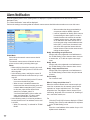
How to Display the "Administrator's Page" ................................................................. 43
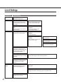
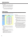
List of Settings ............................................................................................................ 45
System Type .............................................................................................................. 46
Camera Setting .......................................................................................................... 47
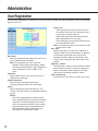
Camera Properties ..................................................................................................... 49
Camera Sleep Schedule ............................................................................................ 51
Camera Sleep Schedule Properties ........................................................................... 52
Recording Status List ................................................................................................. 54
Disk Space Allocation for Camera # ........................................................................... 55
Disk Space Setting for Camera # ............................................................................... 56
Disk Space Addition for Camera # ............................................................................. 57
Delete Disk Space for Camera # ................................................................................ 58
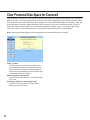
Clear Protected Disk Space for Camera # ................................................................. 59
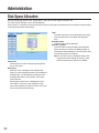
Disk Space Allocation ................................................................................................. 60
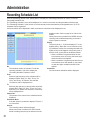
Recording Schedule List ............................................................................................ 61
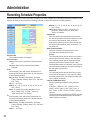
Recording Schedule Properties .................................................................................. 62
Alarm Recording ......................................................................................................... 64
2
Authentication ............................................................................................................. 66
Group ......................................................................................................................... 67
User ............................................................................................................................ 68
User List ..................................................................................................................... 69
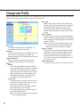
User Registration ........................................................................................................ 70
Change User Profile ................................................................................................... 71
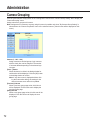
Camera Grouping ....................................................................................................... 72
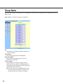
Group Name ............................................................................................................... 73
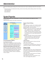
System Properties ...................................................................................................... 74
Alarm Notification ....................................................................................................... 77
E-Mail Setting ............................................................................................................. 78
Stop and Restart ........................................................................................................ 79
Troubleshooting................................................................................................................ 80
3
FEATURES
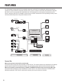
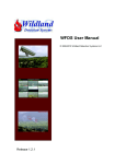
The PC Software Package WV-AS710 (hereinafter referred to as WV-AS710) is designed to deliver pictures from
cameras at remote locations to personal computers (PCs) via an IP network such as the Internet/Intranet. Install the
WV-AS710 in a PC server whose OS is Red Hat Linux 8.0 Professional to run the network camera server (a PC
server in which the WV-AS710 is installed is referred to as a network camera server in this operating manual). Users
can browse delivered pictures using web browsers on PCs.
Coaxial Cable
LAN Cable
Network Interface Unit WJ-NT104
Camera
Network Interface Unit
Modem/Router
Hub etc.
PC
LAN Cable
PC Software Package
WV-AS710
Network Camera
Web Server Apache 2.0.40
LAN Cable
OS Red Hat Linux 8.0Professional
Network Camera
Coaxial Cable
Camera
PC Server
Camera
Disk Space for
Recorded Pictures
Camera
Hard Disk
LAN Cable
Network Camera Server
Network Interface Unit WJ-NT104
Camera
Network Interface Unit
Camera Site
Center Site
User Site
Camera Site
When using cameras connected by coaxial cable
Access the network using the network interface unit WJ-NT104. The network camera server identifies the IP address
and the camera channels of the network interface unit, and acquires camera pictures and controls the cameras.
When using network cameras with built-in 10BASE-T/100BASE-TX Ethernet port connected by LAN cable
Access the network assigning unique IP addresses to each camera. The network camera server identifies the IP
addresses assigned to each camera, and acquires camera pictures and controls the cameras.
4
User Site
Users can browse camera pictures by entering the address of the network camera server in the address box of a
web browser in the same way they access web pages using a web browser. Users don’t need to remember the IP
address of each camera thanks to menus displayed in the web browser that allow them to select and operate the
desired camera.
When connected cameras are compatible with MPEG-4, users can browse camera pictures in the MPEG-4 format
by downloading the MPEG-4 Plug-in Software from the network camera server and installing it in the PC. Users also
can download recorded pictures from the network camera server and play them as MPEG-4 motion pictures.
It is required to download the MPEG-4 Player to play downloaded pictures. Download the MPEG-4 Player from the
network camera server and install it in the PC.
Network Monitoring
By using the network camera server, users can browse JPEG or MPEG-4 format pictures from cameras at remote
locations in the same way they access web pages using a web browser. Multiple users can browse pictures from the
same camera simultaneously, and also each user can browse pictures from different cameras.
Recordings
Authenticated users can record camera pictures delivered to the network camera server on to hard disks.
Alarm Recordings
When the network camera server receives an alarm signal from a camera, pictures from the camera can be recorded on to a hard disk when an alarm occurs. In this case, sending e-mail to specified addresses to notify of an alarm
occurring is also possible. The recipients of the alarm mail can browse the recorded camera pictures by following a
link contained in the mail.
Note: The network camera server receives alarm signals only when cameras use the Panasonic protocol to transmit
alarm signals.
Administration
Administration of the network camera server (for example, setting of camera numbers) can be performed using a
web browser installed on a PC connected to the Internet.
It is unnecessary to install special software on a PC since the network camera server is fully operable with a web
browser.
5
FEATURES
■ System Requirements
System requirements for using the network camera server differ depending on the sites, as described below
Center site
Prepare a PC meeting the following requirements to install the WV-AS710 on.
PC
Memory
LAN card
OS
CD-ROM drive
USB port
Hard disk
Core Component
CPU: Pentium III 1.4GHz or higher
512 MB of RAM or more
100BASE-TX controller or 1000BASE-T/TX/SX controller (Installing three controllers is
recommended: for camera sites, for user sites, for maintenance)
Red Hat Linux 8.0 Professional
Required to install the WV-AS710
Required to install the hardware key (using an USB hub is available)
2 GB or more (except disk space for recorded pictures)
Apache HTTP Server 2.0.40 or later
When using the function for alarm notification by e-mail, establishment of a mail system including a mail server is
required.
Camera site
The following cameras can be connected to the network camera server.
Cameras
Controllable cameras
Maximum camera number
WV-NM100, WV-NP472 (Ver. 1.03E or later), WV-NS320, WV-NS324, or cameras that
can be connected to the network interface unit WJ-NT104
WV-NM100, WV-NS320, WV-NS324, or cameras controllable by WJ-NT104
"Live View & Recording": 64 cameras
"Live View Only": 128 cameras
User site
Recommended environment to access the network camera server is as below.
For browsing JPEG
PC
Recommended CPU
Memory
OS
Web browser
6
PC/AT compatible
Intel® Pentium® lll or higher
128MB of RAM or more
Microsoft® Windows® 98 Second Edition
Microsoft® Windows NT® 4.0 SP6a
Microsoft® Windows® Millennium Edition
Microsoft® Windows® 2000 Professional
Microsoft® Windows® 2000 Server
Microsoft® Windows® XP Home Edition
Microsoft® Windows® XP Professional
Microsoft® Internet Explorer 5.5 SP2
Microsoft® Internet Explorer 6.0 SP1
Netscape Navigator 4.78
Notes:
• It is required to configure a web browser to accept cookies from the network camera server. If the web browser is
configured to "Block All Cookies", set it to "Accept All Cookies". If it is configured to prompt you when a cookie is
sent, click the [Allow] button in the displayed dialog window.
• Netscape Navigator can be used only on Microsoft® Windows® XP and/or Microsoft® Windows® 2000. When
Netscape Navigator is used, the recorded time and date will not be displayed during playback of recorded pictures stored on the network camera server.
• When Internet Explorer 5.5 SP2 or 6.0 SP1 is used with either Microsoft® Windows NT® 4.0 SP6a, Microsoft®
Windows® XP Home Edition, and Microsoft® Windows® XP Professional, JavaTM 2 Runtime Environment,
Standard Edition 1.4.1 of Sun Microsystems is required. Confirm the Java Plug-in control panel is installed on the
PC. If it is not installed, access the following address to download it. (The address of the downloading site is subject to change.)
http://java.sun.com/products/plugin/
For browsing camera pictures with MPEG-4 Plug-in Software
PC
PC/AT compatible
Recommended CPU
Intel® Pentium® lll or higher
Memory
128 MB of RAM or more
Monitor (Resolution)
True Color 24 bit or more (XGA or more (1024 x 768 or more))
OS
Microsoft® Windows® 2000 Professional
Microsoft® Windows® 2000 Server
Microsoft® Windows® Millennium Edition
Microsoft® Windows® XP Home Edition
Microsoft® Windows® XP Professional
Web browser
Microsoft® Internet Explorer 5.5 SP2
Microsoft® Internet Explorer 6.0 SP1
For using MPEG-4 Player
PC
Recommended CPU
Memory
Monitor (Resolution)
OS
Hard disk
PC/AT compatible
Intel® Pentium® lll or higher
128 MB of RAM or more
True Color 24 bit or more (XGA or more (1024 x 768 or more))
Microsoft® Windows® 2000 Professional
Microsoft® Windows® 2000 Server
Microsoft® Windows® Millennium Edition
Microsoft® Windows® XP Home Edition
Microsoft® Windows® XP Professional
10 MB or more to install MPEG-4 Player
About Network Environment
Depending on the traffic on the network or the security system of the LAN (e.g. firewall), it may be difficult to display
HTML documents delivered from the network camera server correctly. The HTML documents delivered from the network camera server contain JavaScript and commands to CGIs. When a PC is set to ignore these commands,
HTML documents may not be displayed correctly.
7
FEATURES
Notes:
• When the traffic on the network is heavy
When the transmission speed is slow or the traffic on the network is too heavy to receive image data, it may be
difficult to browse camera pictures and a still picture indicating the failure to acquire an image ("Image capture
has failed.") may appear. When this still picture appears frequently, adjust the time interval for acquiring image
data.
• When a firewall (including software) is installed
• Allow HTTP access to a port for Apache (default port number: 80).
• Allow HTTP access to a port for WV-AS710 (default port number: 8080). The port for WV-AS710 can be
changed during installation.
• Allow access to all of the UDP ports. Otherwise, it is impossible to browse motion pictures (MPEG-4).
■ Standard Accessories
CD-ROM* ................................................................................. 1
Installation guide ....................................................................... 1
Hardware key ........................................................................... 1
* CD-ROM includes the install program of the WV-AS710, the operating instructions (PDF) and the Readme.txt.
Before installation read the Readme.txt.
■ Trademarks and Registered Trademarks
•
•
•
•
•
•
•
•
•
8
Linux is a registered trademark of Linus Torvalds.
RED HAT is a registered trademark of Red Hat, Inc.
Java is a trademark or registered trademark of Sun Microsystems, Inc. in the United States and other countries.
Microsoft, Windows and Windows NT are registered trademarks of Microsoft Corporation in the U.S. and other
countries.
Netscape, Netscape Navigator, Netscape ONE, the Netscape N and Ship's Wheel logos are registered trademarks of Netscape Communications Corporation in the U.S. and other countries. Other Netscape product names
used in this document are also trademarks of Netscape Communications Corporation and may be registered outside the U.S.
Intel and Pentium are trademarks of Intel Corporation.
IBM and xSeries are registered trademarks of IBM Corporation in the U.S. and/or other countries.
Other names of companies and products contained in these operating instructions may be trademarks or registered trademarks of their respective owners.
Distributing, copying, disassembling, reverse compiling, reverse engineering, and also exporting in violation of
export laws of the Software provided with this product, is expressly prohibited.
■ Structure of These Operating Instructions
These operating instructions consist of an "Operation" section for general users, and "Installation" and
"Administration" sections for administrators of the network camera server. These operating instructions are written
on the assumption that users and administrators use Internet Explorer 6.0 SP1 to operate the network camera server. If other browsers are used, the illustrations in these operating instructions may look differently.
"Operation"
This section describes how to access and operate the network camera server from PCs.
"Installation"
This section describes how to install the WV-AS710 on a PC server on which Red Hat Linux 8.0 Professional is
installed.
"Administration"
This section describes how to set and administrate the network camera server.
Readers of This Manual
The "Operation" section is written for users who know how to operate a web browser and have general knowledge
about the Internet.
The "Installation" and "Administration" sections are written for users who know how to administrate Red Hat Linux
8.0 Professional and the Apache HTTP Server, and who also know how to establish a backbone server.
Terms
Meanings of the terms used in these operating instructions are as follows:
Network camera server: A running PC server on which the WV-AS710 is installed.
Network camera: Cameras that can be directly connected to network such as: WV-NM100, WV-NP472, WV-NS320
and WV-NS324.
Disk space for recorded pictures: Disk space used only for recording which is allocated on a mounted hard disk
on the network camera server. (Partition or directory name is /S3_DATAxx.)
PC: A computer on which a Microsoft® Windows® operating system is installed.
Web browser: Software to browse web sites on the Internet (e.g. Netscape Navigator, Internet Explorer, etc.).
Administrator: A user registered in the administrator group.
User: A person who accesses the network camera server using a web browser, and browses camera pictures or
operates cameras.
Alarm picture: A picture captured when an alarm occurs.
Red Hat Linux: Red Hat Linux 8.0 Professional.
Windows: Microsoft® Windows® operating system.
Windows 2000: Microsoft® Windows® 2000 Professional or Microsoft® Windows® 2000 Server.
Windows XP: Microsoft® Windows® XP Professional or Microsoft® Windows® XP Home Edition.
Notes:
• Names of buttons are between square brackets (e.g. the [OK] button).
• Names of menus and items on menus are between double quotation marks (e.g. the "System Properties" menu).
9
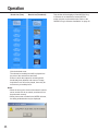
Operation
This section describes how to access the network
camera server in order to browse camera pictures,
operate cameras, and play recorded pictures.
• Access the network camera server using a web
browser. If you don’t have a recommended web
browser, download it from the distributor. Refer to
the "Help" menu of the web browser or to the web
site of a distributor if you need to learn how to operate the web browser.
• It is required to configure the web browser to
accept cookies from the network camera server. If
the web browser is configured to "Block All
Cookies", set it to "Accept All Cookies". If it is configured to prompt you when a cookie is sent, click
the [Allow] button in the displayed dialog window.
• To browse MPEG-4 pictures, the MPEG-4 Plug-in
Software is required. This Plug-in Software is only
for Internet Explorer 5.5 SP2 and 6.0 SP1.
• To browse downloaded MPEG-4 recorded pictures,
the MPEG-4 Player is required.
• To download the MPEG-4 Plug-in Software and the
MPEG-4 Player it is required to agree to the
License Agreement. In the WV-AS710, 32 licenses
are included. Each time the MPEG-4 Plug-in
Software or the MPEG-4 Player is downloaded,
one license is used.
• When accessing the network camera server with
two or more browser windows of a web browser on
a PC, pictures may not be displayed correctly.
• To access cameras with an operating restriction,
the user is required to be registered for authentication. Refer to an administrator for a user name and
a password.
• These operating instructions explain about the
HTML documents installed when the WV-AS710 is
installed. If the HTML documents are edited, layouts and actions may be changed.
10
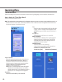
Access to the Network camera server
Perform the following to access the network camera
server to browse camera pictures.
1. Start up the web browser and enter one of the following URLs (refer to a system administrator or a
network administrator about the URL):
• Display in English (Date format: Month/Day/Year)
http://(address of server)/s3/American/
• Display in English (Date format: Day/Month/Year)
http://(address of server)/s3/British/
• Display in Japanese
http://(address of server)/s3/Japanese/
When an address is entered correctly, the "TOP
MENU" will be displayed.
Note: In these operating instructions, procedures are
described on the assumption that the
"http://(address of server)/s3/British/" is entered.
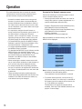
2. To browse camera pictures, click one of the [1] [64] buttons. When "Live View Only" is selected as
the system type of the network camera server, the
[1] - [128] buttons are available.
The buttons for the registered cameras will be
available. Click one of the available buttons to display the "Camera Page".
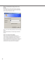
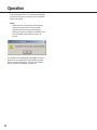
When the authentication dialog window is displayed:
The authentication dialog window will be displayed
when "ON" is selected for "Pre-Authentication Mode"
on the "System Properties" menu.
Enter a user name and a password, and click the [OK]
button.
When authenticated, the "Camera Page" will be displayed.
About "Pre-Authentication Mode"
Users, who have been authenticated when the
"Camera Page" is displayed for the first time, do not
have to be authenticated subsequently. However,
when an authenticated user tries to select or operate a
camera that the user is not allowed to access, the
authentication dialog window will be displayed.
11
Operation
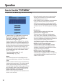
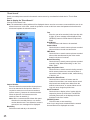
How to Use the "TOP MENU"
To operate the "TOP MENU" page, refer to the following.
• When the network camera server cannot acquire
camera pictures because of connection trouble,
malfunctioning of cameras, etc.
• Even if MPEG-4 Plug-in Software is not installed on
a PC, the network camera server will deliver
MPEG-4 camera pictures. (In this case, this problem will be solved by downloading MPEG-4 Plug-in
Software from the "TOP MENU" page and installing
it.)
• "Camera Page" [1] - [64] (when "Live View &
Recording" is selected as the "System
Type")/[1] - [128] (when "Live View Only" is
selected as the "System Type")
Camera numbers will be displayed. The available
camera numbers are of cameras registered to the
network camera server. When an available button
is clicked, the picture from the selected camera will
be displayed in the selected camera page. The
camera number buttons are different depending on
the selected system type of the network camera
server, as follows:
"Live View & Recording": [1] - [64]
"Live View Only": [1] - [128]
Notes:
Live camera pictures will not be displayed even
when an available button is clicked, in the following
cases.
• When the network camera server stops delivering
camera pictures temporarily. (The network camera
server stops delivering camera pictures during
"Camera Sleep Schedule". Refer to page 51 for further information about "Camera Sleep Schedule".
• When IP addresses of cameras registered to the
network camera server are incorrect.
• When a camera registered to the network camera
server is not connected.
12
• [Help] button
Click this button to display the "Help" page.
• [Administrator's Page] button
Click this button to display the "Administrator's
Page". Only users registered in the administrator
group can display the "Administrator's Page". (The
user name and password registered to the administrator group will be required.) Refer to the
"Administration" section of these operating instructions. Refer to page 43 for further information.
• [MPEG-4 Plug-in Download] button
Click this button to display the MPEG-4 Plug-in
Software download page. The MPEG-4 Plug-in
Software is required to browse MPEG-4 live camera pictures using a web browser.
• [MPEG-4 Player Download] button
Click this button to display the MPEG-4 Player
download page. The MPEG-4 Player is required to
play downloaded MPEG-4 pictures stored on the
network camera server.
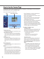
How to Use the Camera Page
To operate the "Camera Page", refer to the following. To display the "Camera Page", click one of the available camera buttons on the "TOP MENU" page.
Click a tab to change the operation menus.
Menu
Picture Display Area
"Live Mode"/"Play Mode" panel
"Camera Select" tab
Click this tab to display the "Camera Select "menu.
"Time & Date Search" tab
Click this tab to display the "Time & Date Search
"menu. Use this menu to search recorded pictures
stored in the network camera server by time and
date.
"Event Search" tab
Click this tab to display the "Event Search" menu.
Use this menu to search recorded pictures stored
in the network camera server by detailed conditions.
Picture Display Area
The selected camera picture or playback picture is
displayed in this area.
Notes:
Live camera pictures will not be displayed even
when an available button is clicked, in the following
cases.
• When the network camera server stops delivering
camera pictures temporarily. (The network camera
server stops delivering camera pictures during
"Camera Sleep Schedule". Refer to page 51 for further information about "Camera Sleep Schedule".
13
• When IP addresses of cameras registered to the
network camera server are incorrect.
• When a camera registered to the network camera
server is not connected.
• When the network camera server cannot acquire
camera pictures because of connection trouble,
malfunctioning of cameras, etc.
• Even if MPEG-4 Plug-in Software is not installed on
a PC, the network camera server will deliver
MPEG-4 camera pictures. (In this case, this problem will be solved by downloading MPEG-4 Plug-in
Software from the "TOP MENU" page and installing
it.) Refer to page 30 for further information.
"Live Mode"/"Play Mode" panel
"Live Mode" panel
Operate the selected camera with this panel in the
following case. Depending on cameras, some of
their functions are not available with this panel.
• Recording camera pictures
• Preset function
• Panning, tilting, zooming and scanning
• Adjustment of focus and brightness
"Play Mode" panel
When "Live View & Recording" is selected as the
system type of the network camera server, this
panel is available. Users can operate this panel to
play recorded pictures stored in the network camera server in various ways.
Notes:
• The available functions differ depending on the
models of connected cameras, and the image
format of pictures delivered by the cameras.
• The "Live Mode" panel will be displayed only
when a camera picture is displayed in the single
screen. (The "Live Mode" panel is not operable
when the quad screen is displayed.)
Operation
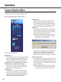
Camera Selection Menu
Use this menu to monitor live camera pictures. Depending on the setting of the network camera server, up to 4 live
camera pictures can be monitored simultaneously.
How to display the camera selection menu
[PREV] button
Click this button to display the "Camera Select"
buttons for the previous sixteen cameras. When
the "Camera Select" buttons are displayed in the
list form, clicking this button displays the "Camera
Select" buttons for the previous four cameras.
[GO] button
Enter the desired camera number in the input box
next to this button, and click this button to display
the camera picture respective to the entered camera number in the picture display area.
Note: When a camera delivering camera pictures
in the MPEG-4 format is selected, the dialog
window below may be displayed.
Click the "Camera Select" tab.
[MODE] button
You can display a list of up to four "Camera Select"
buttons vertically by clicking the [MODE] button.
Clicking the [MODE] button again will display the
"Camera Select" buttons in the original form.
"Camera Select" [1] – [64] buttons ("Live View &
Recording") /[1] – [128] ("Live View Only")
Click one of the "Camera Select" buttons. The
camera picture respective to the clicked button
appears in the picture display area.
[NEXT] button
Click this button to display the "Camera Select"
buttons for the next sixteen cameras. When the
"Camera Select" buttons are displayed in the list
form, clicking this button displays the "Camera
Select" buttons for the next four cameras.
14
This window will be displayed if the MPEG-4 Plugin Software is not installed to browse MPEG-4
motion pictures on a web browser. Refer to the
"MPEG-4 Plug-in Software Installation" on page 30.
[Quad Screen] Button
Click this button to change the single screen in the
picture display area to the quad screen. Up to four
camera pictures are displayed simultaneously. The
"Live Mode" panel is not displayed when the quad
screen is displayed.
Note: This button appears only when the "Quad
Screen Button" of "Monitor Screen Setting" on
the "System Properties" menu is set to "ON".
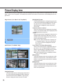
Picture Display Area
The live camera pictures are displayed in the picture display area in the single screen or the quad screen in the "Live
Mode". When in the "Play Mode", recorded pictures stored in the network camera server will be displayed in the single screen.
Single Screen ("Live Mode" and "Play Mode")
Quad Screen ("Live Mode" Only)
[VGA]/[CIF] button
Click the [VGA] button to change the screen size to
the VGA mode when displaying JPEGs. When the
selected camera delivers MPEG-4, click the [CIF]
button to change the screen size to CIF mode.
15
[QVGA]/[QCIF] button
Click the [QVGA] button to change the screen size
to the QVGA mode when displaying JPEGs. When
the selected camera delivers MPEG-4, click the
[QCIF] button to change the screen size to the
QCIF mode.
"Camera # (camera number)"
When the camera picture is displayed in the single
screen, the camera number of the displayed picture
is displayed above the picture.
"TITLE"
When the quad screen is displayed, each picture is
displayed with its respective title above. Click the
desired camera title to display the desired camera
picture in the single screen.
Note: "TITLE" can be edited on the "Camera List"
or "Camera Property" menu by an administrator. "TITLE" will not be displayed if it has not
been entered.
"Live"/"Play" ("Live View & Recording")
When a live camera picture is displayed in the single screen, "Live" is displayed above the picture.
When a recorded picture is displayed in the single
screen, "Play" is displayed above the picture.
Note: When the quad screen is displayed, neither
"Live" nor "Play" appears.
[NEXT] button
This button appears when camera pictures are displayed in the quad screen. Click this button to display the camera pictures for the next four cameras
in the quad screen.
[PREV] button
This button appears when camera pictures are displayed in the quad screen. Click this button to display the camera pictures for the previous four cameras in the quad screen.
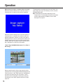
Operation
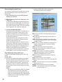
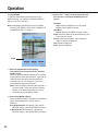
When failure to acquire a camera picture occurred:
When the network camera server could not acquire a
camera picture, the picture below will be displayed.
When the network camera server could not acquire a
camera picture, it is possible to send an e-mail to an
address registered in advance to notify of this failure.
Although access to acquire camera pictures failed, the
network camera server retries to acquire pictures periodically. When also retrying to acquire camera picture
fails, notification by e-mail will not be made.
"Start"/"Stop"/[DOWNLOAD] button ("Live View &
Recording")
When a search result is clicked, the start time of the
camera picture currently played will be displayed in the
"Start" input box. In the "Stop" input box, the displayed
time will be the start time plus 30 minutes. Time to
download can be changed by entering the date and
time directly in the "Start" input box and in the "Stop"
input box.
16
To download the recorded picture from the "Start" time
to the "Stop" time (up to 30 minutes) on a PC, click the
[DOWNLOAD] button.
Note: Download time will differ depending on the
image format. To download 30 minutes of recorded
pictures, approximately 100MB or more of hard
disk space is required.
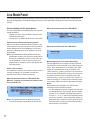
Live Mode Panel
The live mode panel contains the buttons to control the selected camera. (When the quad screen is displayed, this
panel is not displayed.) The buttons displayed in the live mode panel differ depending on the model of the selected
camera.
How to display the live mode panel
When the selected camera is a WV-NM100:
The live mode panel will be displayed by one of the following operations:
• Clicking one of the "Camera Select" buttons in the
camera selection menu.
• Clicking the "Live Mode" tab in the live mode panel.
About the user authentication dialog window:
When a user who is authenticated as a "Monitor" user
clicks a button in the live mode panel, the user authentication dialog window will be displayed. In this case,
perform the authentication as an "Operator" or as an
administrator.
Note: The authentication dialog window will be displayed when a user tries to access a camera which
the user is not allowed to access. In this case, cancel the operation or enter a valid user name and
password to be allowed to access and operate the
selected camera.
About camera control:
It is impossible to operate the camera if another user is
currently operating it (it is possible to access the
selected camera only to view live pictures.)
When the selected camera is a WV-NS320, WVNS324 or a camera connected by the network interface unit WJ-NT104:
Note: The operable buttons will depend on the features of the camera connected by the WJ-NT104.
17
When the selected camera is a WV-NP472:
Manual Recording ("Live View & Recording")
Click the [●] button to record the currently monitored
camera picture on the hard disk of the network camera
server. If the camera picture is recorded in the JPEG
format, the camera picture will be recorded at 1 fps
(JPEG) until the [■] button is clicked. If the camera picture is recorded in the MPEG-4 format, the camera picture will be recorded at the transmission rate of the
camera until the [■] button is clicked. The "Priority" of
manual recording is "4" and pictures recorded by manual recording will be stored in the protected disk space.
Notes:
When pictures are recorded in the JPEG format,
recording interval may differ as below.
• If a recording whose priority is higher than the manual recording priority (for example, alarm recording
(priority: 3) or a schedule recording whose priority
is set to "1", "2" or "3" and whose recorded pictures
are set to be stored in the protected disk space), is
performed during manual recording, pictures will be
recorded at the recording interval of the recording
whose priority is the highest.
Operation
To stop recording, click the [■] button.
Notes:
Manual recording will be stopped in the following
cases. It is impossible to stop recording by closing the
window of a web browser or by shutting down the web
browser.
• When another user accessing the camera while it
is recording clicks the [●] button.
• When an administrator stops or restarts the WVAS710 (Recording will not resume automatically
after restart.)
When the selected camera is delivering JPEG:
When one of the edges (top, bottom, left, right) of
the camera picture is clicked, the camera pans or
tilts toward the clicked direction. (When browsing
MPEG-4, panning and tilting by clicking on the
camera picture is not possible.) The range of panning and tilting by one click differs depending on
the distance between the center point and the
clicked point. For example, if you click the right
edge, the camera pans widely toward the right
side. Tilting is performed in the same way as panning. The camera will not move if the clicked point
is just around the center point.
Notes:
• Even if a point on the camera picture or the arrow
buttons of "Pan/Tilt" is kept pressed, the camera
will not keep on moving.
• Panning and tilting is possible only when one of the
following cameras is selected:
• Camera connected by the network interface unit
WJ-NT104
• WV-NM100
• WV-NS320, WV-NS324
Zoom
Auto Pan
Click the [WIDE] button or the [TELE] button to control
the zoom lens of the selected camera.
Note: Even if the [WIDE] button or the [TELE] button is
kept pressed, the camera will not keep on zooming.
Click the [ON] button to start the AUTO functions set
on the cameras (AUTO PAN, SEQ, SORT, PATROL
and so on). The available functions differ depending on
the settings of the cameras. Refer to the operating
instructions of the cameras for further information. The
way of panning differs depending on the model of the
selected camera.
Click the [OFF] button to stop the AUTO functions.
Clicking other buttons (except the [●] button or the [■]
button of "Manual Recording") also stops the AUTO
functions.
• If manual recording and a recording whose priority
is the same as the manual recording (for example,
schedule recording whose priority is set to "4" and
whose recorded pictures are set to be stored in the
protected disk space) are performed, pictures of
the recording that started later will be recorded at
its recording interval.
• Depending on the setting of "Minimum Access
Interval/Maximum Frame Rate", the recording interval will be different from the examples above.
Refer to page 63 for further information.
Preset
Select a preset position to move the camera to the
selected preset position. Preset position numbers 1 to
64 and home position are available for this function.
The available preset position numbers differ depending
on the model of the selected camera as below:
A camera connected by the WJ-NT104: 1 to 64
WV-NM100: 1 to 8
WV-NS320, WV-NS324: 1 to 16
Note: The preset function is a function of the camera,
not of the network camera server. If the preset
position is not set on the camera, this function is
not available.
Pan/Tilt
Click this button to move the camera horizontally or
vertically. Each click moves the camera horizontally or
vertically by one step. The speed of panning and tilting
and the range of a step differ depending on the model
of the selected camera.
18
Scan
When the [PRESET TOUR] button is clicked, the camera starts touring the preset position number 1 to 8 in
numerical order and stops automatically.
When the [ONE TIME PAN] button is clicked, the camera starts panning once to the right end and once to
the left end, and then stops automatically.
Focus
Click these buttons to adjust focusing.
Click the [NEAR] button to focus on a closer object.
Click the [FAR] button to focus on a farther object.
Click the [AUTO] button to focus on an object in the
center of the displayed picture.
Note: Even if the [NEAR] button or the [FAR] button is
kept pressed, the camera will not keep on focusing.
Iris
Click these buttons to adjust the iris. Generally, to
shoot images with a clear background or to shoot in
bright locations, the iris should be closed.
Click the [OPEN] button to open the iris, so that the
depth of field will be shallower.
Click the [CLOSE] button to close the iris, so that the
depth of field will be deeper.
Click the [RESET] button to return to the default depth
of field.
Note: Even if the [OPEN] button or the [CLOSE] button is kept pressed, the iris will not keep on opening or closing.
Brightness
Click these buttons to adjust the brightness of the camera picture.
Clicking the left side buttons makes the camera picture
darker and clicking the right side buttons makes the
camera picture brighter.
"Play Mode" tab
Click this tab to switch from the "Live Mode" to the
"Play Mode" manually.
19
Operation
Playback of Recorded Pictures
When "Live View & Recording" is selected as the system type of the network camera server, the following recorded
pictures will be stored in the allocated disk space of the network camera server.
• Manually recorded camera pictures by clicking the [●] button of "Manual Recording" on the "Live Mode" panel.
• Automatically recorded camera pictures when an alarm occurred at a camera site. (Set by an administrator)
• Automatically recorded camera pictures by the setting of the recording schedule. (Set by an administrator)
Play recorded pictures stored in the network camera
server as follows:
1. Click the "Time & Date Search" tab or the
"Event Search" tab.
"Time & Date Search":
Search recorded pictures saved in the network
camera server by designating a camera number,
time and date.
"Event Search":
Search recorded pictures saved in the network
camera server by designating more detailed conditions than in "Time & Date Search".
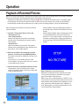
When playback of the recorded picture finishes, a
picture that says "STOP NO PICTURE" will be displayed.
When starting playback without selecting a link text
or a thumbnail from the result list of the "Event
Search" or "Time & Date Search", the last frame of
the latest recorded picture is played, and then the
picture that says "STOP NO PICTURE" will be displayed.
2. Enter the conditions for searching recorded
pictures, and then click the [SEARCH] button.
The search result will be displayed in the main control frame.
To return to the "Time & Date Search" or the
"Event Search" from the results, click the "It returns
to a condition input" link text.
3. Click a link text or a thumbnail from the results.
The playback of the recorded picture will start.
Users can operate buttons on the play mode panel
to play recorded pictures.
20
About playback of recorded pictures:
Playback of recorded pictures is possible only when
"Live View & Recording" is selected as the system
type of the network camera server.
When a user who is authenticated as a "Monitor" user
clicks a button in the play mode control frame, the user
authentication dialog window will be displayed. In this
case, perform the authentication as an "Operator" or
as an administrator, or click the [Cancel] button in the
user authentication dialog window.
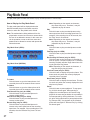
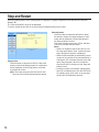
Downloading Recorded Picture
It is possible to download the recorded pictures onto a
PC by designating the start time and stop time for
downloading.
1. Play a recorded picture and confirm the date
and time to download.
2. Display the index.html using a web browser.
The web page below will be displayed.
2. Enter the desired time for the "Start time" and
"Stop time".
It is possible to download recorded picture of up to
30 minutes. When playback starts, the start time of
the recorded picture will be displayed in the "Start
time" input box and the "Start time" plus 30 minutes
will be displayed in the "Stop time" input box.
3. Click the [DOWNLOAD] button.
Follow the displayed instructions. It will take several minutes for the network camera server to prepare the recorded picture to be downloaded. Do
not click any buttons until the network camera server completes preparation.
When download has been completed, the downloaded file will be saved as a self-extracting executable file (file extension: .exe).
When pictures delivered from a camera are in the
JPEG format, JPEG files and html documents will
be downloaded as a self-extracting executable file.
When pictures delivered from a camera are in the
MPEG-4 format, MPEG-4 files (file extension:
.mg4) and an index file (file extension: .idx) will be
downloaded as a self-extracting executable file.
Play Downloaded Recorded Picture
To play the downloaded recorded picture, do the following.
To play JPEG
1. Move the downloaded self-extracting executable
file to the desired folder, and then double click it.
When the downloaded self-extracting file is double
clicked, JPEG files (file extension: .jpg) and html
documents used as a browser (index.html, thumb
html, play.html) will be uncompressed in the selected folder.
Notes:
• Browse the uncompressed JPEG files using the
uncompressed html document (index.html).
• When the size of the picture delivered from the
camera is 640 x 240 pixels, some image editing
software such as "Paint" will display the picture
in the half vertical size.
21
SKIP: Select a number of thumbnail display pages to
be skipped.
TOP: Click this button to go back to the top page on
the left frame.
PREV: Click this button to display the previous page.
The displayed page depends on the selected page
number for "SKIP".
NEXT: Click this button to display the next page. The
displayed page depends on the selected page
number for "SKIP".
LAST: Click this button to go to the last page.
Frame No.: Click this button to display the currently
browsed frame number.
SPEED: Click this button to display the playback
speed. When playing in reverse, the playback
speed will be displayed with a minus (–).
STEP <<: Click this button to go back to a previous
frame and pause.
PLAY: Click this button to start playback.
STEP >>: Click this button to go to the next frame and
pause.
SPEED –: Click this button to slow down the playback
speed one step (–1).
PAUSE: Click this button to pause the playback.
SPEED +: Click this button to speed up the playback
speed one step (+1).
Operation
To play MPEG-4
To play the downloaded recorded picture in the
MPEG-4 format, it is required to install the MPEG-4
Player on the PC in advance.
Note: Downloading the MPEG-4 Player is possible
from the "TOP MENU". Refer to the "Installation of
the MPEG-4 Player" on page 31.
Slider
1. Move the downloaded self-extracting
executable file to the desired folder, and then
double click it.
When the downloaded self-extracting file is double
clicked, MPEG-4 files (file extension: .mg4) and an
index file which includes information about the
recording time, etc. (file extension: .idx) will be
uncompressed in the selected folder.
Note: Place the MPEG-4 files and the index file in
the same folder. If they are placed in different
folders, or the index file is deleted, it may be
impossible to play the MPEG-4 files.
2. Start up the MPEG-4 Player.
When the MPEG-4 Player is installed, the MPEG-4
Player will be added to the "Start" menu in
Windows.
Except Windows XP: [Programs] - [WV-AS710
MPEG-4 Player] - [WV-AS710 MPEG-4 Player]
In Windows XP: [All Programs] - [WV-AS710
MPEG-4 Player] - [WV-AS710 MPEG-4 Player]
22
3. Select "File" - "Open" from the menu bar, and
then select an uncompressed MPEG-4 file to
open it.
File Menu
Open: Select an MPEG-4 file to be played.
Close: Quit the MPEG-4 Player.
Help Menu
About: Displays the MPEG-4 Player version.
Slider: Move this slider to the desired point of playback using the mouse.
Pause: Pauses the playback. Click this button
again to resume the playback.
Play: Starts the playback.
Stop: Stops the playback.
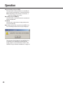
Searching Menu
"Time & Date Search"
Search recorded pictures saved in the network camera server by designating a camera number, date and time.
How to display the "Time & Date Search"
Click the "Time & Date Search" tab.
Note: The authentication dialog window will be displayed when a user tries to access a camera which the user is not
allowed to access. In this case, cancel the operation or enter a valid user name and password to be allowed to
access and operate the selected camera.
Year
Enter the year to be searched in this input box with
4 digits. An error message will be displayed if the
[SEARCH] button is clicked when this input box is
blank.
Hour/Minute
Select the hour and minute to be searched .
Show Thumbnail
Check this box to display a list of results with the
respective pictures in small scale. The MPEG-4
recorded pictures will not be displayed with the
thumbnail in the list of results.
[SEARCH] button
Click this button to start searching.
A list of pictures recorded near the entered time
and date will be displayed as results.
Result List (Text)
Camera Number
Enter the desired camera number whose pictures
are to be searched in this input box. When it is
required to enter two or more camera numbers,
insert a comma (,) between the camera numbers.
When the pictures of all cameras are to be
searched , enter an asterisk (*).
Note: When a camera number without disk space
allocation for recorded pictures, or a camera
number that the user is not allowed to access is
entered, an error message will be displayed.
Month/Day
Select the month and day to be searched .
23
Result List (Thumbnail)
Operation
Click the desired result. The selected recorded picture will be played from the point of time and date
entered for search.
Notes:
• When the time on the clocks of the network
camera server and the PC do not match,
searches will not be performed correctly.
• When pictures are recorded in the MPEG-4 format, the dialog window below may be displayed.
This window will be displayed if the MPEG-4 Plug-in
Software is not installed to browse MPEG-4 motion
pictures on the web browser. Refer to the "MPEG-4
Plug-in Software Installation" on page 30.
24
"Event Search"
Search recorded pictures saved in the network camera server by more detailed criteria than in "Time & Date
Search".
How to display the "Event Search"
Click the "Event Search" tab.
Note: The authentication dialog window will be displayed when a user tries to access a camera which the user is not
allowed to access. In this case, cancel the operation or enter a valid user name and password to be allowed to
access and operate the selected camera.
Camera Number
Enter the desired camera number whose pictures
are to be searched in this input box. When it is
required to enter two or more camera numbers,
insert a comma (,) between the camera numbers.
When the pictures of all cameras are to be
searched, enter an asterisk (*).
Note: When a camera number without disk space
allocation for recorded pictures, or a camera
number that the user is not allowed to access is
entered, an error message will be displayed.
Month/Day
Select the month and day to be searched.
25
Year
Enter the year to be searched in this input box with
4 digits. An error message will be displayed if the
[SEARCH] button is clicked when this input box is
blank.
Hour/Minute
Select the hour and minute to be searched.
Contact Alarm
Check this box to search camera pictures recorded
when an alarm occurred at a camera site.
VMD Alarm
Check this box to search camera pictures recorded
when motion was detected by the video motion
detection function of cameras.
Manual Recording
Check this box to search camera pictures recorded
manually using "Manual Recording" on the "Live
Mode" panel.
Image Acquisition Loss
Check this box to search events including events in
which camera pictures were not sent because of
connection trouble, network trouble, malfunctioning
of devices, etc.
Include Non-Video Event
Check this box to search all events near the
entered time and date, even events whose recorded pictures have already been deleted from the
network camera server, or events without recordings such as an image acquisition loss.
Show Thumbnail
Check this box to display a list of results with the
respective pictures in small scale. The MPEG-4
recorded pictures will not be displayed with the
thumbnail in the list of results.
[SEARCH] button
Click this button to start searching.
A list of up to ten pictures recorded near the entered
time and date will be displayed as results.
Operation
Result List (Text)
Result List (Thumbnail)
Click the desired event.
The selected recorded picture will be played from
the point of the entered time and date.
Events in which the respective recorded picture
has already been deleted, and events of "Image
Acquisition Loss" will not be played, since they do
not have any recorded picture.
Notes:
• When the time on the clocks of the network camera
server and the PC do not match, searches will not
be performed correctly.
• When pictures are recorded in the MPEG-4 format,
the dialog window below may be displayed.
26
This window will be displayed if the MPEG-4 Plugin Software is not installed to browse MPEG-4
motion pictures on the web browser. Refer to the
"MPEG-4 Plug-in Software Installation" on page 30.
Play Mode Panel
The play mode panel contains the buttons to play recorded pictures in various ways.
How to Display the Play Mode Panel
The play mode panel will be displayed when the
desired recorded picture in the search results is
clicked, or when the "Play Mode" tab is clicked.
Note: The authentication dialog window will be displayed when a user tries to access a camera which
the user is not allowed to access. In this case, cancel the operation or enter a valid user name and
password to be allowed to access and operate the
selected camera.
Play Mode Panel (JPEG):
Play Mode Panel (MPEG-4):
To Latest
Click this button to go to the latest picture of all
recorded pictures in the network camera server.
To Oldest
Click this button to go to the oldest picture of all
recorded pictures in the network camera server.
Fast Reverse Play (only for JPEG)
Click this button to play recorded pictures in
reverse at high-speed.
Slow Reverse Play (only for JPEG)
Click this button to play recorded pictures in
reverse at slow speed.
Reverse Play (only for JPEG)
Click this button to play recorded pictures in
reverse at the same speed rate as the recording
speed rate. For example, if the recording time is 30
seconds, also the "Reverse Play" time is 30 seconds.
27
Note: Depending on the network environment,
drop frame may occur. Therefore, it may be
impossible to play all frames.
Play
Click this button to play recorded pictures at the
same speed rate as the recording speed rate. For
example, if the recording time is 30 seconds, also
the "Play" time is 30 seconds.
Note: Depending on the network environment,
drop frame may occur. Therefore, it may be
impossible to play all frames.
Slow Play
Click this button to play recorded pictures at slow
speed.
Fast Play (only for JPEG)
Click this button to play recorded pictures at highspeed.
Reverse Play All Frames (only for JPEG)
Click this button to play all frames of recorded pictures in reverse. Frames are played in 0.2 seconds
intervals. Playback will take longer than when clicking the [Reverse Play] button.
Note: Depending on the network environment, it
may take long to play all frames.
Previous Frame (only for JPEG)
Click this button to display the previous frame. This
button works only when the currently displayed
recorded picture is paused.
Next Frame (only for JPEG)
Click this button to display the next frame. This button works only when the currently displayed recorded picture is paused.
Pause
Click this button to pause playback. To stop pausing, click this button again. When pausing is
stopped, the recorded picture will resume being
played in the same way as before the recorded picture was paused by clicking this button. For example, after clicking this button to pause playback during "Reverse Play", the playback of the recorded
picture will start again in "Reverse Play" by clicking
this button again.
Operation
Play All Frames (only for JPEG)
Click this button to play all frames of recorded pictures. Frames are played in 0.2 seconds intervals.
Note: Depending on the network environment, it
may take a longer time to play.
Back Skip (only for MPEG-4)
Click this button to go back around 3 seconds and
pause the playback.
Live Mode
Click this tab to switch from the play mode to the
live mode manually.
Note: When pictures are recorded in the MPEG-4 format, the dialog window below may be displayed.
This window will be displayed if the MPEG-4 Plugin Software is not installed to browse MPEG-4
motion pictures on the web browser. Refer to the
"MPEG-4 Plug-in Software Installation" on page 30.
28
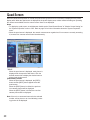
Quad Screen
When the [Quad Screen] button is clicked, the quad screen (pictures from four cameras) is displayed in the picture
display area. When the quad screen is displayed in the picture display area, neither manual recording nor operating
the camera are available since the camera control frame is not displayed.
Notes
• To display the quad screen, an administrator should set the "Quad Screen Button" of "Monitor Screen Setting" on
the "System Properties" menu to "ON". Refer to page 74 for further information about the "System Properties"
menu.
• When the quad screen is displayed, the network camera server regards it as if four users are currently accessing
it, because four cameras are accessed simultaneously.
"TITLE"
When the quad screen is displayed, each picture is
displayed with its respective title above. Click the
desired camera title to display the desired camera
picture in the single screen.
[PREV/NEXT] buttons
When the quad screen is displayed, the [PREV]
button and the [NEXT] button appear below the
quad screen.
When the [PREV] button is clicked, the previous
four camera pictures will be displayed.
When the [NEXT] button is clicked, the next four
camera pictures will be displayed.
Note: If there is no connected camera for the selected
number, a blue picture or an icon indicating a missing picture will be displayed.
29
Operation
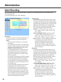
Installation of the MPEG-4 Plug-in Software
To view live pictures or play recorded pictures in the MPEG-4 format, it is required to install the MPEG-4 Plug-in
Software on the PC.
Notes:
• Confirm your PC fulfills the system requirements before installing the MPEG-4 Plug-in Software. Refer to page 7
for further information.
• The MPEG-4 Plug-in Software is not compatible with Windows NT.
• Install or uninstall the MPEG-4 Plug-in Software after logging on to the PC as an administrator (Administrator:
Windows 2000, Computer Administrator: Windows XP).
How to Install
To install the MPEG-4 Plug-in Software, do the following.
1. Display the "TOP MENU" of the network camera server.
http://(server address)/s3/British
The server address differs depending on the user environment.
2. Click the [MPEG-4 Plugin Download] button.
Follow the displayed instructions to download the installer (Setup.exe).
3. Double click the installer (Setup.exe) to start installation.
The installer will start up. Follow the displayed instructions to complete installation.
How to Uninstall
To uninstall the MPEG-4 Plug-in Software, do the following.
Except Windows XP
1. Open the control panel. ([Start] - [Settings] - [Control Panel])
The control panel will be opened.
2. Double click the [Add/Delete Application].
3. Select [MPEG-4 Viewer Software] and click [Change/Remove].
4. Follow the displayed instructions to complete uninstall.
In Windows XP
1. Open the control panel. ([Start] - [Control Panel])
The control panel will be opened.
2. Double click the [Add/Delete Application].
3. Select [MPEG-4 Viewer Software] and click [Change/Remove].
4. Follow the displayed instructions to complete uninstall.
30
Installation of the MPEG-4 Player
To play downloaded recorded pictures in the MPEG-4 format, it is required to install the MPEG-4 Player on the PC.
Notes:
• Confirm your PC fulfills the system requirements before installing the MPEG-4 Player. Refer to page 7 for further
information.
• The MPEG-4 Player is not compatible with Windows NT.
• Install or uninstall the MPEG-4 Player after logging on to the PC as an administrator (Administrator: Windows
2000, Computer Administrator: Windows XP).
How to Install
To install the MPEG-4 Player, do the following.
1. Display the "TOP MENU" of the network camera server.
http://(server address)/s3/British
The server address differs depending on the user environment.
2. Click the [MPEG-4 Player Download] button.
Follow the displayed instructions to download the installer (Setup.exe).
3. Double click the installer (Setup.exe) to start installation.
The installer will start up. Follow the displayed instructions to complete installation.
When the MPEG-4 Player has been installed, the MPEG-4 Player will be added to the "Start" menu in Windows.
Except Windows XP: [Programs] - [WV-AS710 MPEG-4 Player] - [WV-AS710 MPEG-4 Player]
In Windows XP: [All Programs] - [WV-AS710 MPEG-4 Player] - [WV-AS710 MPEG-4 Player]
How to Uninstall
To uninstall the MPEG-4 Player, do the following.
Except Windows XP
1. Open the control panel. ([Start] - [Settings] - [Control Panel])
The control panel will be opened.
2. Double click the [Add/Delete Application].
3. Select [WV-AS710 MPEG-4 Player] and click [Change/Remove].
4. Follow the displayed instructions to complete uninstall.
In Windows XP
1. Open the control panel. ([Start] - [Control Panel])
The control panel will be opened.
2. Double click the [Add/Delete Application].
3. Select [MPEG-4 Viewer Software] and click [Change/Remove].
4. Follow the displayed instructions to complete uninstall.
31
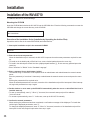
Installation
To install the WV-AS710, adequate knowledge of Red Hat Linux is required. Also, adequate knowledge of Apache
HTTP Server will be required to access the network camera server from a network.
Note: Installation of the WV-AS710 on the Red Hat Linux server, allocation of disk space for recorded pictures, and
uninstallation of the WV-AS710 must be performed by a root user.
Procedures to Establish the Network Camera Server
To use the network camera server, perform the following.
1. Selection of the system type of the network camera server
2. Confirmation of the directory structure
3. Installation of Red Hat Linux
4. Allocation of disk space for recorded pictures (when "Live View & Recording" is selected)
5. Installation of the WV-AS710 (Execution of the installation script)
6. Startup of the WV-AS710
7. System environment setting
Before running the network camera server, access the "Administrator’s Page" and set the system environment.
Refer to the "Administration" section on page 43.
8. Running of the network camera server
After setting the system environment, restart the WV-AS710. The settings will be validated and the network camera server will start running.
32
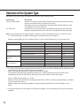
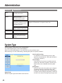
Selection of the System Type
Depending on the system type, the network camera server works in different ways.
System Type
Live View & Recording
Description
Delivery of live camera pictures and recording can be performed. (Allocation of disk
space for recorded pictures is required on the server.)
Recorded pictures can be searched for and played when desired, and they can be
downloaded on a user's PC hard disk.
Only delivery of live camera pictures is available with this system type. Recording,
playback, searching and the alarm function are not available with this system type.
Live View Only
Note: The system type can be changed anytime if required. In case of switching from the "Live View Only" to the
"Live View & Recording", allocation of disk space for recorded pictures will be required.
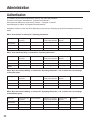
Design a system fulfilling all of the conditions below to run the network camera server in each system type.
Items
Live View & Recording
Live View Only
Maximum camera number
64
128*1
Maximum total bit rate
15Mbps
30Mbps
Maximum total frame rate
200fps
200fps
User Site
Maximum concurrent access
100
200
(Live)
Maximum total bit rate
30Mbps
30Mbps
Camera Site
Maximum total frame rate
200fps
200fps
User Site
Maximum concurrent access
64
-
(Playback)
Maximum total bit rate
15Mbps
-
Maximum total frame rate
200fps
-
User Site
Maximum concurrent access
100
-
(Live & Playback)*2
Maximum total bit rate
30Mbps
-
Maximum total frame rate
200fps
-
*1 To connect 128 cameras, it is required to set the maximum bit rate at less than 230kbps and the maximum frame
rate at less than 1.5fps per a camera in the camera settings.
Refer to the following values for the maximum frame rate of cameras.
The following values may differ depending on objects to be captured and the network environment. Also,
depending on the traffic on the network, acquiring pictures at the maximum frame rate may fail.
Size of a JPEG (QVGA): Approx.15 - 22 KB
Maximum frame rate of WJ-NT104: 5fps (Settings of WJ-NT104: JPEG, Fixed Input Selection Mode, no limitation
for maximum bit rate, QVGA).
Maximum frame rate of WJ-NM100 (MPEG-4): 30fps (Settings of WV-NM100: bit rate of 256kbps or more,
QCIF).
*2 In the case where the user site obtains 64 accesses for playback, up to 36 accesses for viewing live pictures are
available.
33
Installation
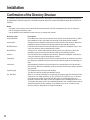
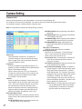
Confirmation of the Directory Structure
The network camera server uses the following directories. Disk space for recording pictures should be allocated by
an administrator. (Refer to page 36.) The other directories below are created automatically when the WV-AS710 is
installed.
Notes:
• The path of the directory to store the html documents and the CGI files will depend on the user environment.
• Do not change the directory name.
• Do not delete the files installed in each directory or change their names.
Directory name
/usr/local/s3/bin/
/usr/local/s3/
$HTMLPath/s3/
$CGIPath/s3/
/var/run/
/var/log/s3/
/var/s3/etc/
/var/lib/mysql/
/S3_DATAxx/
34
Description
Executable files of the network camera server will be stored in this directory. When
the installation script is executed, this directory will be automatically created.
Setting files of the network camera server will be stored in this directory. When the
installation script is executed, this directory will be automatically created.
HTML documents will be stored in this directory. When the installation script is executed, this directory will be automatically created.
CGI files to be used for administration will be stored in this directory. When the
installation script is executed, this directory will be automatically created.
Process ID files will be created in this directory. When the installation script is executed, this directory will be automatically created.
Log files such as an alarm log file and an access log file will be created in this directory. When the installation script is executed, this directory will be automatically created.
Administration information of the disk space for recorded pictures will be stored in
this directory. When the installation script is executed, this directory will be automatically created.
The database will be stored in this directory.
This directory will be used by the database server.
When "Live View & Recording" is selected for the system type, this directory will be
required (xx: two digits number (e.g. /S3_DATA00/, /S3_DATA01/, etc.)). The network camera server will use this as the disk space for recorded pictures. It is
required to allocate disk space for this as a partition when installing Red Hat Linux.
To allocate disk space for this after installing Red Hat Linux, an administrator has to
allocate disk space for this manually. It is possible to use up to 16 disks for this
directory. Refer to the page 36 for further information.
Installation of Red Hat Linux
When installing Red Hat Linux, take notice of the following.
About Disk Space for Recorded Pictures (When "Live View & Recording" is Selected)
When "Live View & Recording" is selected as the system type, allocation of disk space for recorded pictures will be
required.
To allocate disk space for recorded pictures when installing Red Hat Linux, use the following mount name.
/S3_DATAxx (xx: 2 digit number)
Refer to page 36 for further information.
When it is required to allocate or add disk space after installing Red Hat Linux, use the name above as the mount
name.
Cautions when Installing Red Hat Linux
It is recommended to install all the packages when selecting package groups during the installation of Red Hat
Linux. Selecting all packages using "Custom Install" can install all the packages included in Red Hat Linux.
The following packages are required to run the network camera server.
• Desktop Environment
• Graphical Internet
• Text-based Internet
• Server Configuration Tools
• Web Server
• Mail Server
• DNS Name Server
• SQL Database Server (Click "Detail" to add "mysql-server".)
• Network Server
• Administration Tools
Access the address below after completing installation, and download and install an upgrade file to upgrade MYSQL
to the latest version. The address below is subject to change without notice.
https://rhn.redhat.com/errata/rh8-errata.html
35
Installation
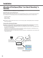
Allocation of Disk Space (When "Live View & Recording" is
Selected)
To allocate disk space for recorded pictures, refer to the following.
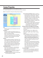
About Disk Space for Recorded Pictures
When the network camera server runs on the "Live View & Recording" system, it is required to allocate disk space
for recorded pictures. The following functions will be available by allocating disk space for recorded pictures.
• Schedule recording
• Alarm recording
• Manual recording
Note: When the network camera server runs on a "Live View Only" system, allocating disk space for recorded pictures is not necessary.
Cautions When Allocating Disk Space
Depending on the place the disk space for recorded pictures has been allocated, the performance of the network
camera server may deteriorate. To prevent deterioration of the performance, refer to the following:
• It is recommended to prepare a hard disk exclusively for recorded pictures, and to create a new partition as the
disk space for recorded pictures.
• If data which is not recorded pictures is stored in the partition created as disk space for recorded pictures, the
performance of the network camera server may deteriorate.
• After allocating disk space for recorded pictures, allocate disk space for recorded pictures of each camera in the
"Administrator's Page".
q
root
Recording by the
cameras set on the
menus of "Recording".
S3_DATA00
Creating disk space for
recorded pictures on the
server.
w Allocating disk space for
recorded pictures on the
menus of "Recording".
e Setting cameras for recording on
the menus of "Recording".
36
How to Allocate Disk Space
There are two following ways to allocate disk space.
• Use a whole partition as disk space for recorded pictures.
• Use a directory as disk space for recorded pictures.
Creating a New Partition to Use as Disk Space for Recorded Pictures
When preparing a new hard disk or creating a new partition on a currently used hard disk, the new partition must be
the following name to mount. It is possible to create this partition when installing Red Hat Linux.
"/S3_DATAxx" xx: two digits number (e.g. /S3_DATA00, /S3_DATA01, etc.)
Notes:
• When a new hard disk is prepared exclusively for recorded pictures, do not create any other partition than
"/S3_DATAxx".
• Do not install any other software in the "/S3_DATAxx" partition.
• Select "ext2" for the file system. If "ext3" or other file systems are selected, the performance of the network camera server may deteriorate.
• The network camera server will not recognize a partition if its name is not "/S3_DATAxx".
Using an Existing Partition as Disk Space for Recorded Pictures
It is possible to create a new directory on an existing partition to use as disk space for recorded pictures. In this
case, proceed as follows:
1. Create a directory in the existing partition and name the new directory "/S3_DATAxx" with the "mkdir"
command.
Note: The network camera server will not recognize a directory if its name is not "/S3_DATAxx".
2. Set a symbolic link for the created directory to be recognized as "/S3_DATAxx".
Example
If the "S3_DATA02" directory is created in the "/mnt2" partition, enter the following to set a symbolic link for the
"S3_DATA02" directory.
#mkdir /mnt2/S3_DATA02/
#ln -s /mnt2/S3_DATA02 /
37
Installation
Installation of the WV-AS710
To install the WV-AS710, do the followings.
Mounting the CD-ROM
Insert the CD-ROM that includes the WV-AS710 into the CD-ROM drive. Enter the following commands to mount the
CD-ROM and change the current directory to the CD-ROM.
#mount /mnt/cdrom
#cd /mnt/cdrom
Execution of the Installation Script (Installation by Unpacking the Archive Files)
Unpack the archive files in the mounted CD-ROM, and install the files.
1. Start up the installation script in the mounted CD-ROM.
#./s3inst
2. Enter the environment parameter.
When the installation script is executed, the WV-AS710 requests the environment parameters required for startup.
• To install not in the default path of Red Hat Linux, enter a desired path and press the return key.
• To install in the default path of Red Hat Linux (displayed path between [ ]), do not enter any path and press the
return key.
• Enter "American" or "British" for the "Standard Language".
3. Enter a password for an administrator (admin).
The entered string of characters will be a password for an administrator who administrates the network camera
server.
Enter the password (of more than 5 characters) to administrate the network camera server and press the return
key.
Entering the password will be required twice.
When the entered passwords do not match, execution of the installation script will be interrupted. When interrupted, begin this procedure from step 1 again.
4. Decide whether or not to start up the WV-AS710 automatically when the server on which Red Hat Linux is
installed starts up.
• To start up automatically, enter "y". When "y" is entered, the automatic startup script will be added to
"/etc/rc.d/rc.local".
• To not start up automatically, enter "n". In this case, start up the WV-AS710 manually.
5. Confirm the entered parameters.
When entering the parameters has been completed, a confirmation message will be displayed. To install after
confirming the displayed parameters, enter "y"
To change the displayed parameters, enter "n". When "n" is entered, execution of the installation script will be
interrupted. In this case, begin this procedure from step 1 again.
38
6. Create disk space for recorded pictures.
When disk space for recorded pictures is not prepared in advance, a message asking whether to create or not
disk space for recorded pictures on an existing partition will be displayed. When "Live View & Recording" will be
selected as the system type and it will be required to create disk space for recorded pictures, enter "y". When it is
unnecessary to create disk space or when adding disk space later (for example, installing a new hard disk later),
enter "n".
Unmounting the CD-ROM
When the installation of the WV-AS710 on Red Hat Linux has been completed, enter the following commands to
unmount the CD-ROM.
#cd /
#umount /mnt/cdrom
Starting up the Network Camera Server
Installation of the Hardware Key
The WV-AS710 will not be started up if the provided hardware key is not installed on the PC server.
Before starting up the WV-AS710, insert the provided hardware key into a USB port on the PC server.
It is also possible to insert the hardware key into a USB hub connected to the PC server.
Start up from the "Administrator's Page"
After the installation of the WV-AS710, the first startup of the WV-AS710 can be made using the "Administrator's
Page".
To display the "Administrator's Page", click the [Administrator's Page] button on the "TOP MENU" page.
"TOP MENU" page address:
http://(server address)/s3/American/
http://(server address)/s3/British/
The server address differs depending on the user environment.
When the authentication dialog window is displayed, enter "admin" for user name and the password entered when
installing the WV-AS710.
39
Installation
When the network camera server has not yet started up, the server start confirmation page will be displayed.
Click the [Start WV-AS710] button to start up the WV-AS710.
Start up from Red Hat Linux
Execute "s3" in the directory where the WV-AS710 is installed.
When the WV-AS710 is installed in the default path, it has been installed in "/usr/local/s3/bin/".
#/usr/local/s3/bin/s3
Notes:
• Executing "s3" is not necessary if "Start WV-AS710 automatically when starting Linux" is selected when the WVAS710 is installed, and the server is restarted.
• When the automatic startup of the WV-AS710 or the manual restart of the WV-AS710 by an administrator is performed, the WV-AS710 will start running in the background. Therefore, nothing will be displayed in the terminal
window.
The Settings of the Network Camera Server Just after Completing the Installation are as Follows:
Item
System Type
Camera
IP address of the camera
Camera group
Channel of the connected camera
Disk space
Access mode
User
Password
Schedule
Alarm function
40
Parameter
Live View & Recording
A single camera
192.168.0.10
None
1ch of WJ-NT104
Not allocated
Continuous
"admin" only
Password entered when installing the WV-AS710
None
None
After the Installation of the WV-AS710
To run the network camera server after installation, do the following.
E-Mail System Establishment
The network camera server can send e-mail to registered e-mail addresses when an alarm occurs.
To use this function, establishment of a mail server system is required. Refer to the operating instructions of the mail
server software for further information.
Environment Settings of the Network Camera Server
Refer to the "Administration" section on page 43 for further information about the environment settings.
Stop the WV-AS710
To stop the WV-AS710, click the [Stop] button on the "Stop and Restart" menu. Refer to page 79 for further information.
41
Installation
Uninstallation
When uninstallation of the WV-AS710 is needed, execute the script for uninstallation.
When the script for uninstallation is executed, all directories created when the WV-AS710 was installed will be deleted, except the newly created partitions or directories for disk space named "S3_DATAxx" (their contents will be
deleted.).
Note: The uninstallation of the WV-AS710 must be performed by a root user.
The script for uninstallation was installed in the following directory when the WV-AS710 was installed.
/usr/local/s3/bin/uninstall/
To uninstall the WV-AS710, enter the following commands.
#cd /usr/local/s3/bin/uninstall/
#./s3uninst
42
Administration
To run the network camera server, it is required to access the "Administrator's Page" to perform the settings.
Refer to this chapter on how to access the "Administrator's Page", and the settings required to be set.
How to Display the "Administrator's Page"
1. Start up the web browser and display the "TOP
MENU" of the network camera server.
http://(server address)/s3/British/
The server address differs depending on the
user environment.
2. Click the [Administrator's Page] button.
The authentication dialog window will be displayed.
The "Administrator's Page" can be displayed by
entering the following address. In this case, the
authentication dialog window will also be displayed.
http://(server address)/s3/British/cfg
Note: To perform the settings of the network camera server, use Internet Explorer 5.5 SP2 or 6.0
SP1. If other browsers are used, the settings
cannot be performed correctly.
3. Enter a user name and a password, and then
click the [OK] button.
User name: Enter the user name belonging to the
"admin" group.
43
Password: Enter the password corresponding to
the entered user name.
Just after installation, only the user name "admin"
is registered in the "admin" group. The password
for the user name "admin" is the password entered
when installing the WV-AS710.
When the user is authenticated, the
"Administrator's Page" will be displayed.
4. Click the desired button in the "Setting Menu".
Some types of "Setting Menu" have two or more
tabs. Click the desired tab to display the menu to
be set.
5. Click the [Save] or [Save...] button on each
menu page to save the changed settings.
A dialog window for confirmation will be displayed.
Follow the displayed instructions to complete the
settings.
Administration
6. To stop or restart the WV-AS710, display the
"Stop and Restart" menu. ([System] button–
[Stop and Restart] tab)
When the [Restart] button is clicked
When the [Stop] button is clicked
7. Click the [Restart] button to restart, or the
[Stop] button to stop the WV-AS710.
A dialog window for confirmation will be displayed.
44
Click one of the following buttons in the dialog window.
OK: To stop or restart the WV-AS710.
Cancel: To go back to the "Stop and Restart"
menu.
List of Settings
Setting Menu
Tab/Setting Page
System Type
System Type
Selects the system type.
Camera
Camera List
Displays the list and performs
the basic settings of the camera
properties.
Camera Properties
Performs more detailed settings
than the "Camera List" menu.
Camera Sleep Schedule
List
Camera Sleep Schedule
Properties
Performs the settings for the
camera sleep schedule.
Displays the list for the camera
sleep schedule.
Recording
Recording Status List
Displays the recording status.
Disk Space Allocation for
Camera #
Allocates disk space.
Disk Space Setting for
Camera #
Selects the menu to perform the
settings for disk space.
Disk Space Addition
Adds disk space.
Delete Disk Space
Deletes disk space.
Clear Protected Disk Space
Clears protected disk space.
Disk Space Allocation
Allocates the same amount of
disk space simultaneously to the
cameras which no disk space
has been allocated yet.
Recording Schedule List
Displays the list for the recording
schedule.
Recording Schedule Properties
Performs the settings for the recording schedule.
Alarm Recording
Performs the recording parameter settings when an alarm
occurs.
User/Camera
Group
User List
Displays the Registered users
and their belonging groups.
User Registration
Adds users.
Change User Profile
Changes passwords or belonging group of registered users.
Camera Grouping
Assigns users to groups.
45
Administration
Setting Menu
Tab/Setting Page
User/Camera
Group
Group Name
Changes group names.
System
System Properties
Performs the basic settings of
the network camera server.
Alarm Notification
Performs the settings for how the
network camera server informs
of an alarm occurring.
E-Mail Setting
Registers e-mail addresses of recipients for alarm mail.
Stop and Restart
Stops or restarts the WV-AS710.
TOP MENU
Goes to the "TOP MENU".
EXIT
Exits from the "Administrator's
Page" and closes the browser
window.
System Type
Click the [System Type] button on the "Setting Menu".
The "Select System Type" menu will be displayed.
Select "Live View & Recording" or "Live View Only" from the pull-down menu.
When selecting "Live View & Recording", allocating disk space is required in advance.
System Type
Select the system type of the network camera server.
46
Live View & Recording
It is possible to record camera pictures on disk
space for recorded pictures. (Disk space allocation
is required in advance.)
Live View Only
Only delivery of live pictures is available with this
system type. Recording, playback, searching and
alarm function are not possible with this system
type.
[Save] button
Click this button when the system type is changed.
The dialog window for confirmation will be displayed. Click the [OK] button on the dialog window
to confirm. After clicking the [OK] button, restart the
WV-AS710 to make the changed system type valid.
Camera Setting
Camera List
Click the [Camera] button on the "Setting Menu" or click the "Camera Setting" tab.
The "Camera List" menu will be displayed. It is useful to check the registered cameras with this page.
It is possible to register or delete cameras using this menu.
Note: It is impossible to change the settings during recording.
Camera No.
Click the desired "Camera No." to display the
"Camera Properties" menu of the desired camera.
Refer to page 49 for further information about the
"Camera Properties" menu.
IP Address
Enter the IP address of the selected camera. It is
possible to enter the FQDN (Fully Qualified Domain
Name) of the selected camera.
When a camera uses an HTTP port, except port
number 80, to deliver pictures, enter (colon (:) port
number) just after the IP address or the FQDN.
For example: 192.168.0.50:85
Channel
When the registered camera is connected to a network interface unit (WJ-NT104), select the channel
(1CH - 4CH) of the network interface unit used for
the selected camera from this pull-down menu.
When the registered camera is connected directly
without a network interface unit (WV-NP472, WVNS320, WV-NS324, WV-NM100), select "1CH".
Unit Type/Image Format
Select the model of the connected camera, and the
image format of the camera picture that the camera
delivers.
WJ-NT104/JPEG: When registering a camera connected to WJ-NT104, select this.
47
WV-NP472/JPEG: When registering a WV-NP472,
select this.
WV-NS320/JPEG: When registering a WV-NS320
or WV-NS324, select this.
WV-NM100/JPEG: When registering a WV-NM100
delivering JPEG camera pictures, select this.
WV-NM100/MPEG-4: When registering a WVNM100 delivering MPEG-4 camera pictures,
select this.
Title (Up to 16 characters)
Assigning a title to the camera is available.
Operating Restriction
Select one of "Unrestricted", "View And Preset
Only" or "By Camera Group Setting" to restrict
users' access to the camera or not.
Unrestricted: When "Unrestricted" is selected, all
users can access and operate the camera,
except for recording.
View And Preset Only: Browsing live pictures and
preset operations are possible.
By Camera Group Setting: Register a camera to
groups using the "Camera Group Setting" page
first ([User/Camera Group] button - (Camera
Group Setting) tab). The "Operator" type users
belonging to the group can operate this camera,
including for recording. The "Monitor" type
users belonging to the group only can view live
pictures and preset operations. The other users
cannot operate this camera at all.
Note: Basically, recording pictures can be done
only by administrators. When "By Camera
Group Setting" is selected, the "Operator"
type users also can record pictures.
Administration
Unit Setting
Click the [Setup] button to display the setting menu
(html) of the camera. Available settings are different depending on the connected camera. Refer to
the operating instructions of the connected camera
for further information about the setting menu.
[Delete] button
Click the [Delete] button to delete the selected registered camera from the "Camera List" menu.
When this button is clicked, the dialog window for
confirmation will be displayed. Click the [OK] button
in the dialog window to complete. Click the [Cancel]
button to cancel the deletion.
[Save…] button
Click this button to save the edited settings.
When this button is clicked, the network camera
server updates the settings.
Note: If any other menu is displayed without clicking this button after editing, the settings in the
network camera server will not be updated.
Click the [Cancel] button to cancel to update
settings.
[Previous] link text
When the "Camera List" menu has two or more
pages because many cameras are registered, and
the currently displayed page is not the first page,
this link text will be displayed. Click this link text to
display the previous page.
[Next] link text
When the "Camera List" menu has two or more
pages because many cameras are registered, and
the currently displayed page is not the last page,
this link text will be displayed. Click this link text to
display the next page.
48
Camera Properties
Click the desired "Camera No." in the "Camera List" menu.
The "Camera Properties" menu of the selected camera will be displayed.
Note: It is impossible to change the settings during recording.
Title
Assigning a title of up to 16 characters to the camera is possible.
IP Address
Enter the IP address of the selected camera. It is
possible to enter the FQDN (Fully Qualified Domain
Name) of the selected camera.
When a camera uses an HTTP port, except port
number 80, to deliver pictures, enter (colon (:) port
number) just after the IP address or the FQDN.
For example: 192.168.0.50:85
Channel
When the registered camera is connected to a network interface unit (WJ-NT104), select the channel
(1CH - 4CH) of the network interface unit used for
the selected camera from this pull-down menu.
When the registered camera is connected directly
without a network interface unit (WV-NP472, WVNS320, WV-NS324, WV-NM100), select "1CH".
Operating Restriction
Select one of "Unrestricted", "View And Preset
Only" or "By Camera Group Setting" to restrict
users' access to the camera or not.
Unrestricted: When "Unrestricted" is selected, all
users can access and operate the camera,
except for recording.
View And Preset Only: Browsing live pictures and
preset operations are available.
49
By Camera Group Setting: Register a camera to
groups using the "Camera Group Setting" page
first ([User/Camera Group] button - (Camera
Group Setting) tab). The "Operator" type users
belonging to the group can operate this camera,
including for recording. The "Monitor" type
users belonging to the group only can view live
pictures and preset operations. The other users
cannot operate this camera at all.
Note: Basically, recording pictures can be done
only by administrators. When "By Camera
Group Setting" is selected, the "Operator"
type users also can record pictures.
Minimum Access Interval/Maximum Frame Rate
Select an interval time for accessing the selected
camera to capture pictures. The default setting is "1
Sec. (1fps)".
0.066 Sec. (15fps), 0.1 Sec. (10fps), 0.2 Sec.
(5fps), 0.5 Sec. (2fps), 1 Sec. (1fps), 2 Sec., 3
Sec., 5 Sec., 10 Sec., 30 Sec., 60 Sec., 120 Sec.,
180 Sec.
Note: Depending on the traffic on the network, it
may be difficult to browse camera pictures.
When the following occur frequently, adjust the
interval time for capturing camera picture:
• When it is difficult to acquire camera pictures
because the transmission speed is slow or the
traffic on the network is too heavy to receive
camera pictures.
• When around 5 seconds pass after accessing
the network camera server, and the picture that
says "Image capture has failed." is displayed.
• When many cameras are set at short interval
times, it may cause heavy network traffic. It
may cause not only incorrect access interval,
but also critical network problems.
Access User Name
In cases where user authentication is required to
access the camera or the network interface unit,
enter the user name registered for the camera or
the network interface unit here.
Administration
Access User Password
In cases where user authentication is required to
access the camera or the network interface unit,
enter the password registered for the camera or the
network interface unit here.
Note: It is required to enter the "Access User
Name" and "Access User Password" when
using WV-NM100, WV-NS320 or WV-NS324.
These are the user name and password registered to access the camera or the network interface unit, and are totally different from the user
name and password required to access the network camera server. Some of the cameras may
have an access level. Depending on the
entered "Access User Name" and "Access User
Password", it may be impossible to operate
some of the cameras from the network camera
server.
Refer to the operating instructions of the camera.
Access Mode
Select an access mode from "Continuous" or "On
Demand".
Continuous: The network camera server will keep
on capturing pictures.
On Demand: The network camera server will capture pictures only in the following cases:
• When a user selects a camera
• When the start time of the recording schedule
comes
• When an alarm occurs
Note: When the alarm recording is set and
"Continuous" is selected, it may not start alarm
recording until a connection has been completed from the moment that the alarm occurred.
Unit Type/Image Format
Select the model of the connected camera, and the
image format of the camera picture that the camera
delivers.
WJ-NT104/JPEG: When registering a camera connected to WJ-NT104, select this.
WV-NP472/JPEG: When registering a WV-NP472,
select this.
WV-NS320/JPEG: When registering a WV-NS320
or WV-NS324, select this.
WV-NM100/JPEG: When registering a WV-NM100
delivering JPEG camera pictures, select this.
WV-NM100/MPEG-4: When registering a WVNM100 delivering MPEG-4 camera pictures,
select this.
50
Pre-Recording
Select "Allowed" or "Denied" to activate the prerecording or not.
When "Allowed" is selected, the network camera
server will record camera pictures just before an
alarm occurs. Pre-recording duration can be selected in the "Alarm Recording" menu.
Note: Pre-recording duration cannot be set differently for each camera.
[Save…] button
Click this button to save the edited settings.
When this button is clicked, the dialog window for
confirmation will be displayed. Click the [OK] button
in the dialog window to update the settings.
Note: If any other menu is displayed without clicking this button after editing, the settings in the
network camera server will not be updated.
[Save & Next Camera] button
Click this button to save the edited settings, and go
to the "Camera Properties" menu of the next camera.
When this button is clicked, the dialog window for
confirmation will be displayed. Click the [OK] button
in the dialog window to update the settings.
[Camera List] link text
Click this link text to return to the "Camera List"
menu.
Camera Sleep Schedule
Camera Sleep Schedule List
Click the [Camera] button of the "Setting Menu" to display the "Camera List" menu, and click the "Camera Sleep
Schedule" tab.
The "Camera Sleep Schedule" menu will be displayed. It is useful to check the camera sleep schedules with this
page.
The "Camera Sleep Schedule" is the function to stop delivery of camera pictures, and to display a prepared still picture at the designated time. Up to 20 schedules can be registered.
Click the "Camera Sleep Schedule" tab.
Active schedules will be displayed in black, and inactive schedules will be displayed in red.
Priority
The priority level will be displayed. "1" is the highest priority. When two or more camera sleep
schedules overlap, the camera sleep schedule with
higher priority will be applied. If the priority level is
also the same, priority will be decided as follows:
• When a schedule is registered while the network camera server is running, the latest registered schedule will be applied.
• When a schedule is registered just after the network camera server has started up, the schedule with higher schedule number will be applied.
Comments
Comments about schedules will be displayed.
No.
The schedule number is indicated. To edit the camera sleep schedule, click this to display the
"Camera Sleep Schedule" menu.
From
Start time (day and time) of the schedule will be
displayed.
To
End time (day and time) of the schedule will be displayed.
Camera No.
The number of the camera to be scheduled will be
displayed.
51
Administration
Camera Sleep Schedule Properties
Click a desired "No" on the "Camera Sleep Schedule List" menu to display the "Camera Sleep Schedule Properties"
menu. Perform the settings for the selected camera sleep schedule or delete the selected camera sleep schedule.
To
Schedule No.
The schedule number is indicated.
Active/Inactive
Active: Select this to activate the selected schedule.
Inactive: Select this to inactivate the selected
schedule.
From
Select the day, hour and minute (increments of 5
minutes) from the pull-down menu time for the start
time of the selected schedule.
Day: Monday, Tuesday, Wednesday, Thursday,
Friday, Saturday, Sunday, Mon. to Fri., Sat. and
Sun., Daily
Hour: 0 – 23, Every
Minute: 0, 5, 10, 15, 20, 25, 30, 35, 40, 45, 50, 55
(min.), Every
Note: To activate "Camera Sleep Schedule" for 24
hours, select "Daily" for "Day", "Every" for
"Hour" and "Every" for "Minute".
52
Select the day, hour and minute (increments of 5
minutes) from the pull-down menu time for the end
time of the selected schedule.
Day: Monday, Tuesday, Wednesday, Thursday,
Friday, Saturday, Sunday, Mon. to Fri., Sat. and
Sun., Daily
Hour: 0 – 23, Every
Minute: 0, 5, 10, 15, 20, 25, 30, 35, 40, 45, 50, 55
(min.), Every
Note: When "Daily" for "Day" is selected, it is
required to select "Every" for "Hour" and
"Every" for "Minute".
Camera No.
Enter the desired camera number to be used for
the selected schedule. When two cameras or more
are used for this schedule, insert a comma ","
between the camera numbers. When all cameras
are used for this schedule, enter an asterisk "*" in
this input box.
Priority
Select the priority level (1 – 4) from the pull-down
menu. "1" is the highest priority. The picture to be
delivered will differ according to the priority. When
two or more camera sleep schedules overlap, the
picture with higher priority will be delivered.
The sample pictures will be installed in the directory below when the WV-AS710 is installed.
The details of the sample pictures are listed below.
/usr/local/s3/bin
File name
blue1.jpg/blue1.mg4
Designed for
Priority 1
blue2.jpg/blue2.mg4
Priority 2
blue3.jpg/blue3.mg4
Priority 3
blue4.jpg/blue4.mg4
Priority 4
Message
"Live streaming video is currently unavailable." This message will be
displayed when delivery of the camera pictures is stopped by the
"Camera Sleep Schedule" of priority 1.
"This camera is currently unavailable." This message will be displayed
when delivery of the camera pictures is stopped by the "Camera Sleep
Schedule" of priority 2.
"This server is currently unavailable. Please try later." This message
will be displayed when delivery of the camera pictures is stopped by the
"Camera Sleep Schedule" of priority 3.
"Image capture has failed." This message will be displayed when delivery of the camera pictures is stopped by the "Camera Sleep Schedule"
of priority 4.
According to your needs, replace the JPEG (.jpg) sample pictures with customized JPEG pictures by naming them
with the same name as the sample pictures.
The size of a customized JPEG picture should be less than 100kbyte, and the recommended resolution is 320 x 240
pixels.
It is impossible to replace the MPEG-4 files (.mg4).
Comments
Write comments about the selected schedule.
[Save…] button
Click this button to save the settings of the "Camera Sleep Schedule" menu. When this button is clicked, the dialog window for confirmation will be displayed. Click the [OK] button in the dialog window to confirm.
[Delete…] button
Click this button to delete the selected camera sleep schedule. When this button is clicked, the dialog window for
confirmation will be displayed. Click the [OK] button in the dialog window to confirm.
[Camera Sleep Schedule List] link text
Click this link text to display the "Camera Sleep Schedule List" menu.
Notes:
• When two or more schedules are in succession, the accuracy of sequential recording of the schedules may not
be guaranteed. Live pictures may be delivered temporarily between the schedules.
• When a camera sleep schedule is changed, live pictures may be delivered temporarily until the changed schedule is validated.
53
Administration
Recording Status List
Click the [Recording] button of the "Setting Menu" or click the "Recording Status" tab.
The "Recording Status List" menu will be displayed. It is useful to check the status of disk space for each camera
with this page.
Camera No.
Click the desired "Camera No." to perform the settings for the disk space of the selected camera.
If the disk space for the selected camera has
not yet been allocated :
The "Disk Space Allocation for Camera #" menu
will be displayed. (# is the selected camera number)
If disk space for the selected camera has
already been allocated:
The "Disk Space Setting for Camera #" menu will
be displayed. (# is the selected camera number.)
IP Address
The IP address of each connected camera is displayed.
Channel
The channel of each camera connected by the network interface unit is displayed.
Title
The title of each connected camera is displayed.
Recording Status (ASM)
The status of recording (Alarm Recording,
Schedule Recording or Manual Recording) of each
connected camera is displayed.
Red -: Alarm Recording
Blue -: Schedule Recording
Black -: Manual Recording
During recording, "–" becomes "+".
54
Allocated Space (MB)
The allocated disk space for each connected camera is displayed. (Unit size: MB)
Used Space
The used disk space for each connected camera is
displayed as a bar graph. The type of recording
can be identified by the color of the bar graph.
Gray: This color part is used by pre-recording.
Red: This color part is used as protected disk
space by the network camera server. (When
the protected disk space is cleared, the red part
will turn black.)
Blue: This color part is unprotected disk space of
the network camera server.
Black: This color part is unused disk space.
Pre-Recording Time (Sec.)
The pre-recording time (recording time before an
alarm occurs) will be displayed. This will be displayed only when both the following are executed:
• On the "Camera Properties" menu of the selected camera, "Allowed" is selected for "Prerecording".
• "ON" is selected for " Recording", and a value
of "Duration" for "Pre-Recording" is selected on
the "Alarm Recording" menu.
Comments
The status of the disk space for each connected
camera is displayed.
The following comments will be displayed according to the status:
• Formatting the disk space.
• Adding the disk space.
• Deleting the disk space.
• Clearing the protected disk space.
[Previous] link text
When the "Recording Status List" menu has two or
more pages because many cameras are registered, and the currently displayed page is not the
first page, this link text will be displayed.
Click this link text to display the previous page.
[Next] link text
When the "Recording Status List" menu has two or
more pages because many cameras are registered, and the currently displayed page is not the
last page, this link text will be displayed.
Click this to display the next page.
Disk Space Allocation for Camera #
Click the desired "Camera No." of the camera to which no disk space has been allocated yet in the "Recording
Status List" menu. The "Disk Space Allocation for Camera #" menu will be displayed. (# is the selected camera number)
Allocate the disk space for the selected camera on this menu.
Available Disk Space
The available disk space will be displayed. (Unit
size: MB).
Space To Be Allocated (%) (percentage of the
available disk space which can be used)
Enter the percentage of the disk space for the
selected camera to be allocated as a designated
proportion (%). When another input box is clicked
after entering the percentage number, the entered
percentage will be converted into megabytes, and
the converted value will be displayed in the input
box "Space To Be Allocated (MB)" automatically.
55
Space To Be Allocated (MB)
Enter the size of the disk space for the selected
camera to be allocated as a designated size (MB).
When another input box is clicked after entering the
amount of disk space, the entered size will be converted into the respective percentage and the converted value will be displayed in the input box
"Space To Be Allocated (%) (percentage of the disk
space which can be used)" automatically.
Note: It is impossible to enter a number bigger
than the "Available Disk Space".
[Allocate…] button
Click this button to format and allocate the disk
space. When this button is clicked, a dialog window
for confirmation will be displayed. Click the [OK]
button in the dialog window to complete.
[Recording Status List] link text
Click this link text to return to the "Recording Status
List" menu.
Administration
Disk Space Setting for Camera #
Click the desired "Camera No." of the camera to which the disk space has already been allocated in the "Recording
Status List" menu. The "Disk Space Setting for Camera #" menu will be displayed. (# is the selected camera number)
This menu has the following links.
• "Disk Space Addition" link text
• "Delete Disk Space" link text
• "Clear Protected Disk Space" link text
[Disk Space Addition] link text
Click this link text to display the "Disk Space
Addition for Camera #". (# is the selected camera
number)
[Delete Disk Space] link text
Click this link text to display the "Delete Disk Space
for Camera #". (# is the selected camera number)
[Clear Protected Disk Space] link text
Click this link text to display the "Clear Protected
Disk Space for Camera #" menu. (# is the selected
camera number)
[Recording Status List] link text
Click this link text to return to the "Recording Status
List" menu.
56
Disk Space Addition for Camera #
Click the desired "Camera No." of the camera to which the disk space has already been allocated in the "Recording
Status List" menu. The "Disk Space Setting for Camera #" menu will be displayed. (# is the selected camera number)
Click the "Disk Space Addition" link text to display the "Disk Space Addition for Camera #". (# is the selected camera
number)
Adding disk space for the selected camera to increase recording time is possible on this page.
Upper Part
#. /S3_DATAxx/
The name of the disk space and the allocated size
for the selected camera will be displayed. (# is the
number of disk space, xx is a two digits number)
Middle Part
Allocated Disk Space
The size of the disk space allocated for the selected camera will be displayed.
Available Disk Space
The available disk space possible to allocate to the
selected camera will be displayed.
Bottom Part
Space To Be Added (%) (percentage of the
available disk space which can be used)
Enter the desired percentage of the available disk
space to allocate to the selected camera. When
another input box is clicked after entering percentage number, the entered percentage will be converted into megabytes and the converted value will
be displayed in the input box "Space To Be Added
(MB)" automatically. The total size allocated for the
selected camera will also be recalculated and displayed in the "Total" automatically.
57
Space To Be Added (MB)
Enter the desired size (MB) of the available disk
space to allocate for the selected camera. When
another input box is clicked after entering the
amount of disk space, the entered size (MB) will be
converted into a percentage and the converted
value will be displayed in the input box "Space To
Be Added (%)" automatically. The total size allocated for the selected camera will also be recalculated
and displayed in the "Total" automatically.
Note: It is impossible to enter a number bigger
than the "Available Disk Space".
Total
Enter the desired total size (MB) of the disk space
to allocate for the selected camera. When another
input box is clicked after entering the number for
total size, the entered total size (MB) will be converted into a percentage and the converted value
will be displayed in the input box "Space To Be
Added (%)" and "Space To Be Added (MB)" automatically.
Note: It is impossible to enter a number bigger
than the "Available Disk Space".
[Add…] button
Click this button to add disk space for the selected
camera. When this button is clicked, the disk space
will be added and the total size of disk space will
be the same size as displayed in the "Total" input
box.
[Recording Status List] link text
Click this link text to return to the "Recording Status
List" menu.
[Disk Space Setting for Camera #] link text
Click this link text to return to the "Disk Space
Setting for Camera #" menu.
Administration
Delete Disk Space for Camera #
Click the desired "Camera No." of the camera to which the disk space has already been allocated in the "Recording
Status List" menu. The "Recording Status for Camera #" menu will be displayed. (# is the selected camera number)
Click the "Delete Disk Space" link text to display the "Delete Disk Space for Camera #". (# is the selected camera
number)
Upper Part
The status of the disk space for the selected camera will be displayed. When recording is in process,
deletion is impossible.
Middle Part
The name and size of the disk space allocated for
the selected camera will be displayed.
Bottom Part
The total size of the disk space allocated for the
selected camera will be displayed.
[Delete…] button
Click this button to delete the allocated disk space
for the selected camera from the disk space for
recorded pictures. When this button is clicked, the
dialog window for confirmation will be displayed.
Click the [OK] button in the dialog window to complete.
[Recording Status List] link text
Click this link text to return to the "Recording Status
List" menu.
[Disk Space Setting for Camera #] link text
Click this link text to return to the "Disk Space setting for Camera #" menu.
58
Clear Protected Disk Space for Camera #
Click the desired "Camera No." of the camera to which the disk space has already been allocated in the "Recording
Status List" menu. The "Recording Status for Camera #" menu will be displayed. (# is the selected camera number)
Click the [Clear Protected Disk Space] link text to display the "Clear Protected Disk Space for Camera #". When protected disk space is cleared, available disk space will be increased. This menu is available only when "Protect" is
selected for "Data Protection Mode" on the "Recording Schedule Properties" menu or on the "Alarm Recording"
menu. When there is no protected disk space, "Currently No Protected Disk Space" will be displayed.
Note: All protected recorded pictures will be deleted when the protected disk space is cleared.
[Clear…] button
Click this button to clear the recorded pictures in
the protected disk space for the selected camera.
When this button is clicked, the dialog window for
confirmation will be displayed. Click the [OK] button
in the dialog window to complete.
[Recording Status List] link text
Click this link text to return to the "Recording Status
List" menu.
[Disk Space Setting for Camera #] link text
Click this link text to return to the "Disk Space
Setting for Camera #" menu.
59
Administration
Disk Space Allocation
Click the [Recording] button of the "Setting Menu" and click the "Disk Space Allocation" tab.
The "Disk Space Allocation" menu will be displayed.
On this menu, it is possible to allocate the same amount of disk space simultaneously to the selected cameras which
no disk space has been allocated yet.
Camera No.
Check the box to select cameras requiring allocation of disk space.
Disk Space
After this menu is displayed, the available disk
space for each registered camera will be displayed
automatically, it is calculated by dividing the total
available disk space by the number of the registered cameras.
Entering the desired size (in Megabytes) in the
"Disk Space" input box is also possible. In this
case, when another input box is clicked, the "Total"
will be recalculated automatically.
60
Total
Total disk space that can be allocated for the registered cameras will be calculated and displayed
here.
Available Space
Available space will be displayed.
[Execute...] button
Click this button to start formatting and allocation.
When this button is clicked, the dialog window for
confirmation will be displayed. Click the [OK] button
in the dialog window to complete.
Note: If any other menu is displayed without clicking this button after editing, the settings in the
network camera server will not be updated.
Administration
Recording Schedule List
Click the [Recording] button of the "Setting Menu" to display the "Recording Schedule List" menu, or click the
"Recording Schedule" tab.
The "Recording Schedule" menu will be displayed. It is useful to check the recording schedules with this page.
The "Recording Schedule" is the function to record camera pictures automatically at designated times. Up to 20
schedules can be registered.
Active schedules will be displayed in black, and inactive schedules will be displayed in red.
No.
The schedule number is indicated. To edit the
recording schedule, click this to display the
"Recording Schedule Properties" menu.
From
Start time (day and time) of the schedule will be
displayed. When "Daily" for "Day", "Every" for
"Hour" and "Every" for "Minute" are selected,
"Continuous" will be displayed here.
To
End time (day and time) of the schedule will be displayed. When "Daily" for "Day", "Every" for "Hour"
and "Every" for "Minute" are selected, "Continuous"
will be displayed here.
Camera No.
The number of the camera to be scheduled will be
displayed.
Protection Mode
If the disk space is protected it displays "Protect", if
not "Overwrite".
Interval
The recording interval will be displayed.
When pictures are recorded in the JPEG format,
actual recording interval may be different from the
61
displayed value. Refer to page 63 for further information.
When pictures are recorded in the MPEG-4 format,
recording interval differs depending on the transmission speed of cameras.
Priority
The priority level (1 - 4) will be displayed."1" is the
highest priority. When two or more camera recording schedules overlap, the recording schedule with
higher priority will be applied. If the priority level is
also the same, priority will be decided as follows:
• When a schedule is registered while the network camera server is running, the latest registered schedule will be applied.
• When a schedule is registered just after the network camera server has started up, the schedule with the higher schedule number will be
applied.
Comments
Comments about schedules will be displayed.
Administration
Recording Schedule Properties
Click the desired "No" on the "Recording Schedule List" menu to display the "Recording Schedule Properties" menu.
Perform the settings for the selected recording schedule or delete the selected recording schedule.
Schedule No.
The schedule number is indicated.
Active/Inactive
Active: Select this to activate the selected schedule.
Inactive: Select this to inactivate the selected
schedule.
From
Select the day, hour and minute (increments of 5
minutes) from the pull-down menu for the start time
of the selected schedule.
Day: Monday, Tuesday, Wednesday, Thursday,
Friday, Saturday, Sunday, Mon. to Fri., Sat. and
Sun., Daily
Hour: 0 – 23, Every
Minute: 0, 5, 10, 15, 20, 25, 30, 35, 40, 45, 50, 55
(min.), Every
Note: To activate "Recording Schedule" for 24
hours, select "Daily" for "Day", "Every" for
"Hour" and "Every" for "Minute".
To
Select the day, hour and minute (increments of 5
minutes) from the pull-down menu for the end time
of the selected schedule.
Day: Monday, Tuesday, Wednesday, Thursday,
Friday, Saturday, Sunday, Mon. to Fri., Sat. and
Sun., Daily
Hour: 0 – 23, Every
62
Minute: 0, 5, 10, 15, 20, 25, 30, 35, 40, 45, 50, 55
(min.), Every
Note: When "Daily" for "Day" is selected, it is
required to select "Every" for "Hour" and
"Every" for "Minute".
Camera No.
Enter the desired camera number to be used for
the selected schedule. When two cameras or more
are used for this schedule, insert a comma ","
between the camera numbers. When all cameras
are used for this schedule, enter an asterisk "*" in
this input box.
Data Protection Mode
Select to protect the recorded pictures of the
schedule saved as disk space or not.
Protect
The recorded pictures will be saved in the protected area (protected disk space) in the disk space.
The recorded pictures will be protected until the
recorded pictures are cleared from the "Clear
Protected Disk space for Camera #" menu (# is the
selected camera number) even if the formatting of
the disk space is performed.
Overwrite
The recorded pictures will be saved in the unprotected area in disk space. In this case, the oldest
recorded picture will be overwritten first when disk
space is filled to capacity.
Interval (JPEG Mode Only)
Select a recording interval from the pull-down
menu.
0.066 Sec. (15fps), 0.1 Sec. (10fps), 0.2 Sec.
(5fps), 0.5 Sec. (2fps), 1 Sec. (1fps), 2 Sec., 3
Sec., 5 Sec., 10 Sec., 30 Sec., 60 Sec., 120 Sec.,
180 Sec.
When pictures are recorded in the MPEG-4 format,
recording interval differs depending on the transmission speed of cameras.
Note: When two or more recordings are performed
or depending on the selected values for
"Interval" and "Minimum Access
Interval/Maximum Frame Rate", pictures may
be recorded at a different recording interval
from the set value for "Interval". Refer to "About
Interval" on this page for further information.
Priority
The priority level (1 - 4) will be displayed. "1" is the
highest priority. When two or more camera recording schedules overlap, the recording schedule with
higher priority will be applied. If the priority level is
also the same, priority will be decided as follows:
• When a schedule is registered while the network camera server is running, the latest registered schedule will be applied.
• When a schedule is registered just after the network camera server has started up, the schedule with the higher schedule number will be
applied.
Comments
You can write comments about schedules.
[Save…] button
Click this button to save the settings of the
"Recording Schedule Properties" menu. When this
button is clicked, the dialog window for confirmation
will be displayed. Click the [OK] button in the dialog
window to confirm.
Note: If any other menu is displayed without clicking this button after editing, the settings in the
network camera server will not be updated.
Click the [Cancel] button to cancel to update
settings.
[Delete…] button
Click this button to delete the selected recording
schedule. When this button is clicked, the dialog
window for confirmation will be displayed. Click the
[OK] button in the dialog window to confirm.
[Recording Schedule List] link text
Click this link text to display the "Recording
Schedule List" menu.
About "Interval"
• Relation to "Priority" and "Data Protection
Mode"
When two or more recordings are performed in the
same period of time, "Interval" will change during
recording depending on the following circumstances.
63
1. When "Data Protection Mode" is different
Regardless of the setting for "Priority", recording
will be performed at the recording interval of the
recording whose "Data Protection Mode" is
"Protect". For example, when a manual recording
(priority: 4, recorded pictures are stored in the protected disk space) is performed during a schedule
recording whose priority is set to "2" and also
"Overwrite" is selected for "Data Protection Mode",
pictures will be recorded at the recording interval of
the manual recording.
2. When "Data Protection Mode" is the same
Recording will be performed at the recording interval of the recording whose "Priority" is the highest.
3. When "Priority" and "Data Protection Mode" are
the same
Recording will be performed at the recording interval of the recording started later.
• Relation to "Minimum Access Interval/Maximum
Frame Rate"
Basically, the network camera server records camera pictures when acquiring camera pictures.
Therefore, recording will be performed at the
selected value for "Minimum Access
Interval/Maximum Frame Rate" in the following
cases.
When the selected value for "Interval" is the
same or longer than the selected value for
"Minimum Access Interval/Maximum Frame
Rate"
When the selected value for "Interval" is an integral
multiple value of the selected value for "Minimum
Access Interval/Maximum Frame Rate", recording
will be performed at the selected "Interval".
However, when the selected value for "Interval" is
not an integral multiple value of the selected value
for "Minimum Access Interval/Maximum Frame
Rate", recording will be performed at the selected
"Minimum Access Interval/Maximum Frame Rate".
When the selected value for "Interval" is
shorter than the selected value for "Minimum
Access Interval/Maximum Frame Rate"
In this case, recording will be performed at the
selected "Minimum Access Interval/Maximum
Frame Rate".
Administration
Alarm Recording
Click the [Recording] button of the "Setting Menu" to display the "Recording Schedule List" menu and click the
"Alarm Recording" tab.
The "Alarm Recording" menu will be displayed.
Recording
Select "ON" or "OFF" to record camera pictures, or
not, when an alarm occurs at the camera site.
Notes:
• "Priority" of alarm recording is "3" and cannot
be changed.
• In the case where disk space is not allocated to
a camera at which an alarm occurred, or when
disk space for the camera is full, it will not be
possible to record alarm pictures.
• To record alarm pictures, it is required to validate "Panasonic Protocol" for cameras or network interface unit, and it is also required to
register the IP address of the network camera
server as recipient.
• It is possible to notify through TCP/IP only when
devices transmitting "Panasonic Protocol" and
the network camera server are IP reachable.
• It is not possible to record alarm pictures by the
internal alarm of a camera connected to a network interface unit.
• It will be impossible to identify which camera is
transmitting an alarm signal if a router is
installed between a camera site and the network camera server, and when sharing an IP
address at the center site for two or more cameras using network address translation. In this
case, the network camera server will regard the
camera with the lowest camera number as the
camera transmitting the alarm signal.
64
Pre-Recording
Select how many seconds before an alarm occurs,
the network camera server starts recording. When
recording in the JPEG format, alarm pictures will be
recorded at the selected interval for "Interval (JPEG
Mode Only). When pictures are recorded in the
MPEG-4 format, recording interval differs depending on the transmission speed of cameras.
Duration: --- (None), 2 Sec., 3 Sec., 5 Sec., 10
Sec., 20 Sec., 30 Sec., 60 Sec., 90 Sec., 120
Sec., 180 Sec.
Interval (JPEG Mode Only): 0.066 Sec. (15fps),
0.1 Sec. (10fps), 0.2 Sec. (5fps), 0.5 Sec.
(2fps), 1 Sec. (1fps), 2 Sec., 3 Sec., 5 Sec., 10
Sec., 30 Sec., 60 Sec., 120 Sec., 180 Sec.
Note: When two or more recordings are performed
or depending on the selected values for
"Interval" and "Minimum Access Interval/
Maximum Frame Rate", pictures may be
recorded at a different recording interval from
the set value for "Interval". Refer to page 63 for
further information.
Recording
Select how many seconds after an alarm occurs
the network camera server starts recording. When
recording in the JPEG format, alarm pictures will be
recorded at the selected interval for "Interval (JPEG
Mode Only). When pictures are recorded in the
MPEG-4 format, recording interval differs depending on the transmission speed of cameras.
Duration: 1 image only, 2 Sec., 3 Sec., 5 Sec., 10
Sec., 20 Sec., 30 Sec., 60 Sec., 90 Sec., 120
Sec., 180 Sec.
Interval (JPEG Mode Only): 0.066 Sec. (15fps),
0.1 Sec. (10fps), 0.2 Sec. (5fps), 0.5 Sec.
(2fps), 1 Sec. (1fps), 2 Sec., 3 Sec., 5 Sec., 10
Sec., 30 Sec., 60 Sec., 120 Sec., 180 Sec.
Note: When two or more recordings are performed
or depending on the selected values for
"Interval" and "Minimum Access Interval/
Maximum Frame Rate", pictures may be
recorded at a different recording interval from
the set value for "Interval". Refer to page 63 for
further information.
Data Protection Mode
Select to protect the recorded alarm pictures saved
on disk space or not.
Protect
The recorded alarm pictures will be saved in the
protected area (protected disk space) of the disk
space. The recorded alarm pictures will be protected until they are cleared from the "Clear Protected
Disk space for Camera #" menu (# is the selected
camera number) even if the formatting of the disk
space is performed.
Overwrite
The recorded pictures will be saved in the unprotected area of the disk space. In this case, the oldest recorded picture will be overwritten first when
disk space is filled to capacity.
[Save…] button
Click this button to save the settings of the "Alarm
Recording" menu. When this button is clicked, the
dialog window for confirmation will be displayed.
Click the [OK] button in the dialog window to confirm.
Note: If any other menu is displayed without clicking this button after editing, the settings in the
network camera server will not be updated.
65
Administration
Authentication
The network camera server authenticates users by user name and password.
There are 3 user types, "Administrator", "Operator" and "Monitor".
Users also must belong to a group among "Group1" - "Group20" or "admin".
Users belonging to "admin" are regarded as administrators.
Operable functions for each user differ depending on the user type, belonging group and the operating restriction as
below.
When "Unrestricted" is selected for "Operating Restriction"
User Type
Browsing live camera picture
Preset operation
Operation of a camera Searching and
except preset operation playback
Recording
Administrator
™
™
™
™
™
Operator
™
™
™
™
x
Monitor
™
™
™
™
x
When "View And Preset Only" is selected for "Operating Restriction"
User Type
Browsing live camera picture
Preset operation
Operation of a camera Searching and
except preset operation playback
Recording
Administrator
™
™
™
™
™
Operator
™
™
x
x
x
Monitor
™
™
x
x
x
When "By Camera Group Setting" is selected for "Operating Restriction", and a camera and a user belongs
to the same group
User Type
Browsing live camera picture
Preset operation
Operation of a camera Searching and
except preset operation playback
Recording
Administrator
™
™
™
™
™
Operator
™
™
™
™
™
Monitor
™
™
x
x
x
When "By Camera Group Setting" is selected for "Operating Restriction", and a camera and a user belongs
to the different group
User Type
66
Browsing live camera picture
Preset operation
Operation of a camera Searching and
except preset operation playback
Recording
Administrator
™
™
™
™
™
Operator
x
x
x
x
x
Monitor
x
x
x
x
x
Group
There are two kinds of group, the general user group "Group 1" - "Group 20", and the administrator group "admin".
All users should belong to a group.
The general user group "Group 1 - 20"
The groups "Group 1" - "Group 20" are for general users.
When "By Camera Group Setting" is selected for "Operating Restriction" on the "Camera Properties" menu of a camera, only users belonging to the same group can access the camera.
Even if users belong to the same group, what users can do with access to cameras differs depending on the user
type.
A camera can belong to two or more groups.
Note: The "Administrator's Page" cannot be accessed using a user name and a password assigned to a user
belonging to a general group.
Administrator group "admin"
Only users belong to the administrators "admin" can display the "Administrator's Page".
An administrator has to belong to the "admin" group.
If no user belongs to the "admin" group, it will be impossible to administrate the network camera server since no user
can access the "Administrator's Page".
All users belonging to the "admin" group can operate all cameras, record, play recorded pictures, and administrate
the network camera server by accessing the "Administrator's Page".
Restrictions
There are the following group restrictions.
• A user cannot belong to two or more groups. When a user needs to access cameras belonging to two or more
groups, the user is required to be registered in each group with different user names to access these cameras.
• To assign the camera to a group, select "By Camera Group Setting" for "Operating Restriction" in the "Camera
Properties" menu of the selected camera.
67
Administration
User
Basically, a user must belong to only one group among the 20 general user groups of "Group 1 - 20" or the administrator group "admin". (A camera can belong to two or more groups.)
A user can access only cameras belonging to the same group.
Depending on the user type and the group to which the user belongs, what the user can do with access to cameras
differs.
There are two user types, "Monitor" and "Operator".
When a user is assigned to the general group "Group 1 - 20"
Users belonging to one of these groups can access a camera that belongs to the same group to view live camera
pictures or to operate it.
(When "Unrestricted" is selected for "Operating Restriction" on the "Camera Properties" menu of the selected camera, all users can access the camera to view live camera pictures and operate preset functions.)
Note: To prevent illegal access, it is recommended to not select "Unrestricted" for "Operating Restriction" in the
"Camera Properties" menu of all cameras.
When a user is assigned to the administrator group (admin)
All users belong to this group (administrators) can operate all cameras, record, play recorded pictures, preset operations and administrate the network camera server by accessing the "Administrator's Page".
User Type
There are two user types, "Operator" and "Monitor".
Operator
A user of this type can view live pictures, operate cameras, record, search and play recorded pictures from the
cameras belonging to the same group.
Monitor
A user of this user type only can view live pictures and perform the preset operations of the cameras belonging to
the same group.
User Authentication
A user can operate cameras or functions only when the user is authenticated.
When selecting a camera for which the user is not authenticated, the authentication dialog window will be displayed.
Enter a registered user name and a password to be authenticated for the selected camera, or cancel.
68
User List
Click the [User/Camera Group] button of the "Setting Menu" or click the "User Setting" tab to display the "Recording
Schedule List" menu.
The "User List" menu will be displayed. It is useful to check the registered users with this page.
Note: At least a user has to belong to the "admin" group as an administrator.
If no user belongs to the "admin" group, it will be impossible to administrate the network camera server since no
user can access the administration menus.
As a default setting, a user (user name: admin, group: admin) is already registered (password is the one entered
when installing the WV-AS710).
[User Registration…] button
To register a new user, click this button to display
the "User Registration" menu, and do it on that
menu.
User Name
The list of registered user names will be displayed.
To change a user profile (password, Group, User
Type) or delete a user from the user list, click the
required user name to display the "Change User
Profile" menu of the selected user, and do it on that
menu.
Group Name
The group to which user belongs will be displayed.
69
Administration
User Registration
Click the [User Registration…] button on the "User List" menu to display the "User Registration" menu. On this page,
register a new user.
User Name
Enter an unregistered user name for a new user of
up to 32 alphanumeric characters.
Note: The registered user name cannot be
changed. When registered mistakenly, delete
the user name and register it again. Display the
"User Registration" menu to delete a user
name.
Password
Enter a password for a new user name up to 32
alphanumeric characters.
Confirm Password
Enter the same password entered in the
"Password" input box above for confirmation.
Group
Select a group this user should belong to. The
"Group1 –20" and "admin" are registered as default
groups.
Admin:
Users who administrate the network camera
server (administrators) are required to belong to
this group. All users belonging to the "admin"
group can operate all cameras, record, search,
play recorded pictures, preset operation and
administrate the network camera server by
accessing the "Administrator's Page".
70
Group 1-20
These groups are for general users to access
the network camera server to browse live camera pictures or operate cameras.
What users can do while accessing cameras
differs depending on the user type.
Users belonging to these groups cannot access
the "Administrator's Page".
Note: The names of groups can be changed on the
"Group Name" menu.
User Type
Select a user type for the user from "Operator" or
"Monitor". Refer to the "Authentication" on page 66
for information about what users can do when
accessing cameras. When a user belongs to the
"admin" group, settings for the "User Type" will be
ignored.
[Register…] button
Click this button to add a new user with the entered
profile. When this button is clicked, the dialog window for confirmation will be displayed. Click the
[OK] button in the dialog window to confirm.
[User List] link text
Click this link text to return to the "User List" menu.
Change User Profile
Click the [User Name] on the "User List" menu to display the "Change User Profile" menu. On this page, change the
password, belonging group and the user type of the selected user.
User Name
The selected user name will be displayed. It is
impossible to change the user name.
Password
Enter a new password up to 32 alphanumeric characters when a new password is needed. The
entered password will not be displayed for security.
Confirm Password
Enter the same new password entered in the
"Password" input box above for confirmation.
Group
Admin:
Users who administrate the network camera
server (administrators) are required to belong to
this group. All users belonging to the "admin"
group can operate all cameras, record, search,
play recorded pictures, preset operation and
administrate the network camera server by
accessing the "Administrator's Page".
Group 1-20
These groups are for general users to access
the network camera server to browse live camera pictures or operate cameras.
What users can do while accessing cameras
differs depending on the user type.
Users belong to these groups cannot access
the "Administrator's Page".
Note: The names of groups can be changed on
the "Group Name" menu.
71
User Type
Select a user type for the user from "Operator" or
"Monitor". Refer to the "Authentication" on page 66
for information about what users can do when
accessing cameras. When a user belongs to the
"admin" group, settings for the "User Type" will be
ignored.
[Save…] button
Click this button to save the new profile. When this
button is clicked, the dialog window for confirmation
will be displayed. Click the [OK] button in the dialog
window to confirm.
Note: If any other menu is displayed without clicking this button after editing, the settings in the
network camera server will not be updated.
[Delete…] button
Click this button to delete the selected user. When
this button is clicked, the dialog window for confirmation will be displayed. Click the [OK] button in
the dialog window to confirm. Display the "User
List" menu and check that the deleted user is not in
the "User List" menu.
[User List] link text
Click this link text to return to the "User List" menu.
Administration
Camera Grouping
Click the [User/Camera Group] button of the "Setting Menu" and click the "Camera Group Setting" tab to display the
"Camera Grouping" menu.
Assign cameras to groups on this menu.
Note: Assignment of a camera to a group using this menu is possible only when "By Camera Group Setting" is
selected from the "Camera Properties" menu of the selected camera. (Check boxes will be displayed on this
menu.)
Camera (1 - 64/1 - 128)
Assign cameras to desired groups. Only cameras
with the check box can be assigned. The number
of cameras differs depending on the selected system type.
[Save...] button
When this button is clicked, the dialog window for
confirmation will be displayed. Click the [OK] button
in the dialog window to confirm.
Note: If any other menu is displayed without clicking this button after editing, the settings in the
network camera server will not be updated.
[Previous] link text
When a previous group page exists, this link text
will be displayed. Click this link text to display the
previous group page.
[Next] link text
When a next group page exists, this link text will be
displayed. Click this link text to display the next
group page.
72
Group Name
Click the [User/Camera Group] button of the "Setting Menu" and click the "Group Name" tab to display the "Group
Name" menu.
Note: Addition or deletion of a group is impossible.
No.
The number of the group is indicated. There are "1"
to "20" and "admin".
Group Name
The current group name will be displayed.
New Group Name
Enter a desired new group name of up to 32
alphanumeric characters.
[Save…] button
Click this button to save the new group name.
When this button is clicked, the dialog window for
confirmation will be displayed. Click the [OK] button
in the dialog window to confirm.
Note: If any other menu is displayed without clicking this button after editing, the settings in the
network camera server will not be updated.
73
Administration
Perform the following system settings of the network camera server. Stop or restarting the WV-AS710 is also possible.
• System Properties (Pre-Authentication Setting, Camera Control Setting, Network Setting, Monitor Screen Setting,
Auto Erase Setting)
• Alarm Notification
• Stop and Restart
System Properties
Click the [System] button of the "Setting Menu" or click the "System Properties" tab to display the "System
Properties" menu.
Perform the basic settings of the network camera server.
Camera Control Setting
Pre-Authentication Setting
Pre-Authentication Mode
Select "OFF" to not display the authentication dialog
window until the authentication is required. When "ON"
is selected, the authentication dialog window will be
displayed when accessing a camera for the first time
after a web browser started up. In this case, if an
entered user name and a password are authenticated
once, the authentication dialog window will not be displayed until shutting down the web browser. However,
the authenticated dialog window will be displayed
when accessing a camera to which is not allowed to
access or operate.
74
Mode
Select "Exclusive" to allow a user to operate a camera
exclusively. Select "Time Out" to give a certain time
period to operate a camera exclusively.
Exclusive: If this mode is selected, for example, when
user 1 accesses camera 1, the other users cannot
access camera1 until user 1 accesses another
camera. To prevent continuous "Exclusive" mode,
the "Exclusive" mode will be released automatically
10 minutes after the user has finished operation of
the camera
Time Out: If this mode is selected, a user can operate
a camera exclusively for a certain period of time
(Time Out Period), and the other users cannot
access the camera until the control time has
passed.
Time Out Period
Select an exclusive control time from the pull-down
menu for the "Time Out".
30, 60, 90, 120, 150, 180 (sec.)
The selected value will be ignored when "Exclusive" is
selected for the "Mode" of "Camera Control Setting".
Network Setting
Use a Proxy Server
Select "Use a Proxy Server" with an IP address and a
port number of a proxy server when the network camera server acquires camera pictures via a proxy server
from a camera site.
Enter (colon (:) port number) just after an IP address.
For example: 192.168.0.50:85
When camera pictures are not acquired via a proxy
server, select "Bypass Proxy Server".
Proxy Server Exceptions
When a proxy server is used to capture camera pictures, enter the IP address of the network camera or
the network interface unit when acquiring camera pictures directly not via a proxy server. When entering
two IP addresses or more in this input box is required,
insert a comma "," between the IP addresses.
Maximum Concurrent Access
Select a number for maximum concurrent accesses
from the pull-down menu.
12, 15, 20, 30, 45, 60, 80, 100, 150*, 200*
*: Only when "Live View Only" is selected for the system type of the network camera server.
When number of accesses becomes more than the
selected number, the following picture will be delivered
to users who accessed after it reached the maximum
concurrent access limit.
Monitor Screen Setting
'Quad Screen' Button
Select "ON" to display the "Quad Screen" when the
"'Quad Screen' Button" is clicked. Select "OFF" to not
use the "Quad Screen". When "OFF" is selected, the
[Quad Screen] button will not be displayed.
Transmission Mode
When using cameras delivering MPEG-4 live camera
pictures, select either "Unicast" or "Multicast" to deliver
MPEG-4 live camera pictures to a user site.
Unicast: MPEG-4 live camera pictures will be delivered in unicast mode.
Multicast: MPEG-4 live camera pictures will be delivered in multicast mode. To use this mode, set the
LAN card (eth0) on the PC server to the delivering
side.
75
Note: Pictures from cameras with operating restriction will be delivered in the unicast mode.
(Selecting "Multicast" will be ignored.) This setting does not affect MPEG-4 acquisition. Select
the unicast mode on the setting menu of the
camera delivering MPEG-4.
Interval
When using cameras delivering JPEG camera pictures, select an interval for acquiring pictures. Very
Fast, Fast, Middle, Slow, Very Slow
When the network camera server and a user site is
connected with a line faster than 100Mbps, refer to the
following (picture size of all cameras are the same).
When the selected value for "Interval" is not proper,
the camera pictures will not be displayed correctly.
Maximum Concurrent QVGA
Access
VGA
12
Very Fast
Middle
15
Fast
Middle
20
Fast
Slow
30
Middle
Slow
45
Middle
Very Slow
60
Slow
Very Slow
80
Slow
Not Recommended
100
Slow
Not Recommended
150 (Live View Only)
Very Slow
Not Recommended
200 (Live View Only)
Very Slow
Not Recommended
This setting will be ignored when cameras delivering
MPEG-4 pictures since they deliver pictures according
to the settings of camera.
Administration
Auto Erase Setting
Image Auto Erase
Select a period to keep recorded pictures in the disk
space for recorded pictures.
7 Days, 15 Days, 30 Days, 60 Days, 90 Days, 180
Days, No limitation
When the selected period has passed, the stored
recorded pictures will be deleted.
Event Log Auto Erase
Select a period to keep event information recorded in a
database.
7 Days, 15 Days, 30 Days, 60 Days, 90 Days, 180
Days, No limitation
When the selected period has passed, the event information will be deleted automatically.
It is impossible to search events in the deleted event
information using "Event Search".
[Save…] button
Click this button to save the settings of the "System
Properties" menu. When this button is clicked, the
dialog window for confirmation will be displayed.
Click the [OK] button in the dialog window to confirm.
Note: If any other menu is displayed without clicking this button after editing, the settings in the
network camera server will not be updated.
76
Alarm Notification
Click the [System] button of the "Setting Menu" to display the "System Properties" menu and click the "Alarm
Notification" tab.
The "Alarm Notification" menu will be displayed.
Perform the settings concerning what the network camera server should do when an alarm occurs on this menu.
E-Mail Mode
Select when the network camera server should
send e-mail.
The network camera server will attach an alarm
picture to the e-mail by selecting alarm type.
Notes:
• When notifying of an alarm occurring by e-mail,
set the LAN card (eth0) on the PC server to the
delivering side.
• In the following cases, notifying the correct IP
address of the network camera server by e-mail
may fail:
• When the LAN card (eth0) on the PC server
is not set to the delivering side.
• When a router is installed between the
Internet and the network camera server and
network address translation (NAT) is used.
In this case, open all files whose name
starts from "template_alarm" in
"/usr/local/s3/template/" with an editor software, and change the "%i" part to make
addresses accessible to the Internet.
• In the following cases, it will not be possible to
browse pictures even if an address in an e-mail
is clicked:
• When "Do not notify." is selected for "E-Mail
Mode".
77
• When an alarm has been transmitted by a
camera set to deliver MPEG-4 pictures.
• It will be impossible to identify which camera
is transmitting an alarm signal if a router is
installed between the camera site and the
network camera server, and when sharing
an IP address at the center site for two or
more cameras using network address translation (NAT). In this case, the network camera server will regard the camera with the
lowest camera number as the camera transmitting the alarm signal.
Notify: alarm/image acquisition loss
Send e-mail to the registered e-mail addresses in
the "E-Mail Setting" menu when an alarm occurs at
a camera site, or if it fails to acquire camera pictures.
Notify: alarm
Send e-mail to the registered e-mail addresses in
the "E-Mail Setting" menu when an alarm occurs.
Notify: image acquisition loss
Send e-mail to the registered e-mail addresses in
the "E-Mail Setting" when it fails to acquire camera
pictures.
Do not notify.
Do not send e-mail.
What is "image acquisition loss"?
When the network camera server cannot acquire pictures from a camera site, the network camera server
regards it as "image acquisition loss". The "image
acquisition loss" may happen when a camera is malfunctioning, the power of the camera is off, breaking of
wire, connection trouble, etc.
To
Click the [E-mail List] link text to display the "E-Mail
Setting" menu. Enter e-mail addresses of recipients
on the "E-Mail Setting" menu.
From
Enter the e-mail address of the sender of up to 128
alphanumeric characters.
Administration
[Save…] button
Click this button to save the settings of the "Alarm
Notification" menu. When this button is clicked, the
dialog window for confirmation will be displayed.
Click the [OK] button in the dialog window to confirm.
Note: If any other menu is displayed without clicking this button after editing, the settings in the
network camera server will not be updated.
E-Mail Setting
Click the [E-mail List] link text on the "Alarm Notification" menu to display the "E-Mail Setting" menu. Up to 20 e-mail
addresses of recipients can be registered on this menu.
E-Mail
Enter e-mail addresses of recipients to which an
alarm mail will be sent. (Up to 512 alphanumeric
characters)
To delete an e-mail address, simply delete it from
the input box.
Language
Select the language used in the alarm mail. The
arrangement of the date will be different depending
on the selected language.
Japanese: Japanese: Year/Month/Day
American: American English: Month/Day/Year
British: British English: Day/Month/Year
78
Terminal Type
Select the terminal type of the recipients. The picture size differs depending on the selected terminal
type.
GIF portable telephone: Send an alarm mail to a
portable telephone that can display GIF pictures. The picture size will be 120 (W) x 90 (H)
pixels.
JPEG portable telephone: Send an alarm mail to
a portable telephone that can display JPEG pictures. The picture size will be 160 (W) x 120 (H)
pixels.
PC: Send an alarm mail to a PC. The picture size
will be the same size as the camera delivers.
[Save & Go To Alarm Notification] button
Click this button to save the settings of the "E-Mail
Setting" menu. When this button is clicked, the settings of the "E-Mail Setting" menu will be saved
and the "Alarm Notification" menu will be displayed.
Note: If any other menu is displayed without clicking this button after editing, the settings in the
network camera server will not be updated.
Stop and Restart
Click the [System] button of the "Setting Menu" to display the "System Properties" menu and click the "Stop and
Restart" tab.
The "Stop and Restart" menu will be displayed.
To stop or restart the WV-AS710, click the [Stop] or [Restart] button on this menu.
[Stop] button
Click this button to stop the WV-AS710. When this
button is clicked, the dialog window for confirmation
will be displayed. Click the [OK] button on the dialog window to confirm.
Note: This button stops only the WV-AS710. Red
Hat Linux will not be shut down with this button.
79
[Restart] button
Click this button to restart the WV-AS710. When
this button is clicked, the dialog window for confirmation will be displayed. Click the [OK] button in
the dialog window to confirm.
This button restarts only the WV-AS710. Red Hat
Linux will not restart with this button.
Notes:
• When it is needed to stop the WV-AS710, use
the "Stop and Restart" menu. Confirm the message "Stop Server System" is displayed.
• When forced termination is performed by pressing the Ctrl key and the C key simultaneously or
entering the "kill" command, pictures in the disk
space may be broken. When it is needed to
stop the WV-AS710, always use the "Stop and
Restart" menu.
• During processing, for example, changing disk
space for recorded pictures, the WV-AS710 will
be unable to stop. In this case, try to stop after
the WV-AS710 finished any process.
Troubleshooting
Troubles / Symptoms
80
Points to be checked / Solutions
•Cannot start up the
WV-AS710.
• Is the message of "Can't create s3.pid; running already or permission
denied." displayed?
It seems that the WV-AS710 multiply started. Check if the WV-AS710
is already started or not. If the WV-AS710 has not started yet, the WVAS710 might have been forced to stop last time. Check if "s3.pid" file
exists in the "/var/run/" directory or not. If it exists, delete it.
Failure to acquire pictures.
• Is the WV-AS710 started up?
• Are the power of the network interface unit and the cameras on?
• Are the IP addresses entered in the "Camera Properties" menu correct?
• Depending on the traffic on the network, it may happen that automatic
reload of pictures from a web browser may stop. In this case, click the
reload button of the web browser.
• Is the monitor resolution set to True Color 24 bit or more?
• Are the settings of the network interface unit correct? When the network camera server and the network interface unit are used in the
same system, do not set the network interface unit to "Random Input
Selection Mode". Refer to the operating instructions of the network
interface unit for further information.
Cannot change the image
size using the [VGA]/
[QVGA]/[CIF]/[QCIF] buttons.
• Are "Block All Cookies" or "Invalid" selected or not selected in the settings of the web browser? In both cases, select "Accept All Cookies".
Cannot operate the camera
even though monitoring the
pictures is possible.
• It is possible that another user is operating the camera. Try to operate
it later.
• It is possible that the camera has an operating restriction. Refer to an
administrator about your user type.
• When operating WV-NM100, WV-NS320 or WV-NS324, enter "Access
User Name" and "Access User Password" registered in the setting
menu of the cameras.
Cannot select a camera
using the "Camera List"
menu. / Camera pictures do
not change even though
another camera is selected.
• Is the camera connected?
• Is the same IP address entered in the "IP Address" on the "Camera
Properties" menu and on the setting menu of the camera site?
Troubles / Symptoms
81
Points to be checked / Solutions
The blue still picture is displayed.
• Is the power of the camera on?
• Is the power of the network interface unit on?
• Is the "Active" selected on the "Camera Sleep Schedule Properties"
menu?
• Is it possible to establish the transmission between the network interface unit and the network camera server? Confirm it using "ping" command.
• Are the IP address of the network interface unit and the channel of the
camera correct?
• Is the "ON" selected for the authentication of the network interface
unit? If it is, enter the valid user name and password.
• When using a line with slow data transmission rate such as analog
lines, it may rarely happen that a still picture is displayed. If this happens, select a slower interval for the "Interval" of the "System
Properties" menu.
Cannot perform preset operations.
• Does the camera have the preset function?
• Is the preset position setting performed also for the camera not only for
the software?
The camera does not return
to the home position.
• Does the camera have the preset function?
• Is the home position setting performed also for the camera not only for
the software?
Cannot play. / Cannot
record. / Cannot search.
• Is the user authenticated to operate the camera? If it happens even
though authenticated, refer to an administrator.
No result is displayed when
searching by the recording
time.
• Do the clock both of the server and the PC have the exact time? The
search function refers to the clock of the network camera server. When
the clocks have different times, the search function may work incorrectly. Synchronize both clocks.
• Is the clock of the network camera server correct? The network camera
server refers to the clock of the server for recording. Keep the right
time for the clock of server.
The played picture is not
displayed. / The camera
number and the time are not
displayed when monitoring
the played picture.
• Are the java applets, JavaScript and ActiveX enabled?
Cannot record any more.
• Is the disk space full? If it is, back up the data and clear the protected
disk space, or add the disk space if necessary.
Troubleshooting
Troubles / Symptoms
The registered address was
not notified by e-mail when
an alarm occurred or after
image acquisition loss.
• Is the "Do not notify." selected for the "E-Mail Mode" of the "Alarm
Notification" menu?
• Is the mail system of the server activated correctly? Check from the PC
using the "mail" command if the network camera server is activated
and confirm that mail can be delivered to the designated address.
• Is the mail address correct?
The authentication dialog
window keeps on being displayed even though it is
cancelled each time.
• Force the web browser to shut down. The way to force termination is
different depending on the OS. Refer to the operating instructions of
the OS.
The "TOP MENU" or the
pages to browse the camera
pictures cannot be displayed.
82
Points to be checked / Solutions
•
•
•
•
Is the URL correct?
Is the Apache HTTP Server started up?
Is the description of the html document correct?
Is the description of the setting file for the Apache HTTP Server correct?
Cannot display a part of
JPEG picture.
• When using Internet Explorer 5.5 SP2 on Windows 2000, the bottom
line part of the JPEG may not be displayed. Upgrade the web browser
to Internet Explorer 6.0 SP1.
Cannot acquire camera picture. / Alarm function does
not work correctly.
• When a DDNS server is used, it may happen if the IP address revision
information is accessed before the DNS server updates it. In this case,
using a static IP address is recommended.
Matsushita Electric Industrial Co., Ltd.
Osaka, Japan
http://www.panasonic.co.jp/global/
2003
© Matsushita Electric Industrial Co., Ltd. All rights reserved.
N0403-0
V8QA6138AN
Printed in Japan