1
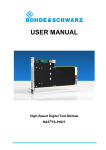
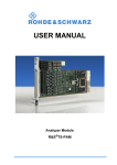
USER MANUAL
Analog/Digital IO Module 2
R&S®TS-PIO2
Note
User Manual
for ROHDE & SCHWARZ Analog/Digital IO Module 2 R&S TS-PIO2
5th Issue/ 09.11 / D 1506.7208.11
All rights, also translation into foreign languages, are reserved. No part of this manual is permitted
to be reproduced in any form (print, photocopy or any other method), also not for the preparation
of lectures, or processed, reproduced or made available using electronic systems without written
permission from ROHDE & SCHWARZ.
® The passing on to third parties and the reproduction of this documentation, utilisation and communication of its contents is not permitted unless specifically approved. Infringements will incur
claims for damages. All rights reserved in the case of the award of a patent or registration of a
design.
R&S® is a registered trademark of ROHDE & SCHWARZ GmbH & Co. KG.
We draw to your attention that the names of software and hardware used in the Service Manual,
and the brand names of the respective companies are, in general, the subject of protection as
trademarks, or under proprietary rights, or patent law.
ROHDE & SCHWARZ GmbH & Co. KG
Corporate Headquarters
Mühldorfstr. 15
D-81671 München
Telephone:
Fax:
...49 (0)89/4129-13774
...49 (0)89/4129-13777
Printed in the Federal Republic of Germany. Errors excepted, subject to technical change without notice.
Basic Safety Instructions
Always read through and comply with the following safety instructions!
All plants and locations of the Rohde & Schwarz group of companies make every effort to keep the safety
standards of our products up to date and to offer our customers the highest possible degree of safety. Our
products and the auxiliary equipment they require are designed, built and tested in accordance with the
safety standards that apply in each case. Compliance with these standards is continuously monitored by
our quality assurance system. The product described here has been designed, built and tested in
accordance with the attached EC Certificate of Conformity and has left the manufacturer’s plant in a
condition fully complying with safety standards. To maintain this condition and to ensure safe operation,
you must observe all instructions and warnings provided in this manual. If you have any questions
regarding these safety instructions, the Rohde & Schwarz group of companies will be happy to answer
them.
Furthermore, it is your responsibility to use the product in an appropriate manner. This product is designed
for use solely in industrial and laboratory environments or, if expressly permitted, also in the field and must
not be used in any way that may cause personal injury or property damage. You are responsible if the
product is used for any intention other than its designated purpose or in disregard of the manufacturer's
instructions. The manufacturer shall assume no responsibility for such use of the product.
The product is used for its designated purpose if it is used in accordance with its product documentation
and within its performance limits (see data sheet, documentation, the following safety instructions). Using
the product requires technical skills and a basic knowledge of English. It is therefore essential that only
skilled and specialized staff or thoroughly trained personnel with the required skills be allowed to use the
product. If personal safety gear is required for using Rohde & Schwarz products, this will be indicated at
the appropriate place in the product documentation. Keep the basic safety instructions and the product
documentation in a safe place and pass them on to the subsequent users.
Observing the safety instructions will help prevent personal injury or damage of any kind caused by
dangerous situations. Therefore, carefully read through and adhere to the following safety instructions
before and when using the product. It is also absolutely essential to observe the additional safety
instructions on personal safety, for example, that appear in relevant parts of the product documentation. In
these safety instructions, the word "product" refers to all merchandise sold and distributed by the Rohde &
Schwarz group of companies, including instruments, systems and all accessories.
Symbols and safety labels
Notice, general
danger location
Observe product
documentation
ON/OFF supply
voltage
Caution
when
handling
heavy
equipment
Standby
indication
1171.0000.42-05.00
Danger of
electric
shock
Direct current
(DC)
Warning!
Hot surface
PE terminal
Alternating current
(AC)
Ground
Direct/alternating
current (DC/AC)
Ground
terminal
Be careful when
handling
electrostatic
sensitive
devices
Device fully protected by
double (reinforced) insulation
Page 1
Basic Safety Instructions
Tags and their meaning
The following signal words are used in the product documentation in order to warn the reader about risks
and dangers.
indicates a hazardous situation which, if not avoided, will result in death or
serious injury.
indicates a hazardous situation which, if not avoided, could result in death or
serious injury.
indicates a hazardous situation which, if not avoided, could result in minor or
moderate injury.
indicates the possibility of incorrect operation which can result in damage to
the product.
In the product documentation, the word ATTENTION is used synonymously.
These tags are in accordance with the standard definition for civil applications in the European Economic
Area. Definitions that deviate from the standard definition may also exist in other economic areas or
military applications. It is therefore essential to make sure that the tags described here are always used
only in connection with the related product documentation and the related product. The use of tags in
connection with unrelated products or documentation can result in misinterpretation and in personal injury
or material damage.
Operating states and operating positions
The product may be operated only under the operating conditions and in the positions specified by the
manufacturer, without the product's ventilation being obstructed. If the manufacturer's specifications are
not observed, this can result in electric shock, fire and/or serious personal injury or death. Applicable local
or national safety regulations and rules for the prevention of accidents must be observed in all work
performed.
1. Unless otherwise specified, the following requirements apply to Rohde & Schwarz products:
predefined operating position is always with the housing floor facing down, IP protection 2X, pollution
severity 2, overvoltage category 2, use only indoors, max. operating altitude 2000 m above sea level,
max. transport altitude 4500 m above sea level. A tolerance of ±10 % shall apply to the nominal
voltage and ±5 % to the nominal frequency.
2. Do not place the product on surfaces, vehicles, cabinets or tables that for reasons of weight or stability
are unsuitable for this purpose. Always follow the manufacturer's installation instructions when
installing the product and fastening it to objects or structures (e.g. walls and shelves). An installation
that is not carried out as described in the product documentation could result in personal injury or
death.
3. Do not place the product on heat-generating devices such as radiators or fan heaters. The ambient
temperature must not exceed the maximum temperature specified in the product documentation or in
the data sheet. Product overheating can cause electric shock, fire and/or serious personal injury or
death.
1171.0000.42-05.00
Page 2
Basic Safety Instructions
Electrical safety
If the information on electrical safety is not observed either at all to the extent necessary, electric shock,
fire and/or serious personal injury or death may occur.
1. Prior to switching on the product, always ensure that the nominal voltage setting on the product
matches the nominal voltage of the AC supply network. If a different voltage is to be set, the power
fuse of the product may have to be changed accordingly.
2. In the case of products of safety class I with movable power cord and connector, operation is
permitted only on sockets with an earthing contact and protective earth connection.
3. Intentionally breaking the protective earth connection either in the feed line or in the product itself is
not permitted. Doing so can result in the danger of an electric shock from the product. If extension
cords or connector strips are implemented, they must be checked on a regular basis to ensure that
they are safe to use.
4. If the product does not have a power switch for disconnection from the AC supply network, the plug of
the connecting cable is regarded as the disconnecting device. In such cases, always ensure that the
power plug is easily reachable and accessible at all times (corresponding to the length of connecting
cable, approx. 2 m). Functional or electronic switches are not suitable for providing disconnection from
the AC supply network. If products without power switches are integrated into racks or systems, a
disconnecting device must be provided at the system level.
5. Never use the product if the power cable is damaged. Check the power cable on a regular basis to
ensure that it is in proper operating condition. By taking appropriate safety measures and carefully
laying the power cable, you can ensure that the cable will not be damaged and that no one can be
hurt by, for example, tripping over the cable or suffering an electric shock.
6. The product may be operated only from TN/TT supply networks fused with max. 16 A (higher fuse
only after consulting with the Rohde & Schwarz group of companies).
7. Do not insert the plug into sockets that are dusty or dirty. Insert the plug firmly and all the way into the
socket. Otherwise, sparks that result in fire and/or injuries may occur.
8. Do not overload any sockets, extension cords or connector strips; doing so can cause fire or electric
shocks.
9. For measurements in circuits with voltages Vrms > 30 V, suitable measures (e.g. appropriate
measuring equipment, fusing, current limiting, electrical separation, insulation) should be taken to
avoid any hazards.
10. Ensure that the connections with information technology equipment, e.g. PCs or other industrial
computers, comply with the IEC60950-1/EN60950-1 or IEC61010-1/EN 61010-1 standards that apply
in each case.
11. Unless expressly permitted, never remove the cover or any part of the housing while the product is in
operation. Doing so will expose circuits and components and can lead to injuries, fire or damage to the
product.
12. If a product is to be permanently installed, the connection between the PE terminal on site and the
product's PE conductor must be made first before any other connection is made. The product may be
installed and connected only by a licensed electrician.
13. For permanently installed equipment without built-in fuses, circuit breakers or similar protective
devices, the supply circuit must be fused in such a way that anyone who has access to the product, as
well as the product itself, is adequately protected from injury or damage.
1171.0000.42-05.00
Page 3
Basic Safety Instructions
14. Use suitable overvoltage protection to ensure that no overvoltage (such as that caused by a bolt of
lightning) can reach the product. Otherwise, the person operating the product will be exposed to the
danger of an electric shock.
15. Any object that is not designed to be placed in the openings of the housing must not be used for this
purpose. Doing so can cause short circuits inside the product and/or electric shocks, fire or injuries.
16. Unless specified otherwise, products are not liquid-proof (see also section "Operating states and
operating positions", item 1. Therefore, the equipment must be protected against penetration by
liquids. If the necessary precautions are not taken, the user may suffer electric shock or the product
itself may be damaged, which can also lead to personal injury.
17. Never use the product under conditions in which condensation has formed or can form in or on the
product, e.g. if the product has been moved from a cold to a warm environment. Penetration by water
increases the risk of electric shock.
18. Prior to cleaning the product, disconnect it completely from the power supply (e.g. AC supply network
or battery). Use a soft, non-linting cloth to clean the product. Never use chemical cleaning agents such
as alcohol, acetone or diluents for cellulose lacquers.
Operation
1. Operating the products requires special training and intense concentration. Make sure that persons
who use the products are physically, mentally and emotionally fit enough to do so; otherwise, injuries
or material damage may occur. It is the responsibility of the employer/operator to select suitable
personnel for operating the products.
2. Before you move or transport the product, read and observe the section titled "Transport".
3. As with all industrially manufactured goods, the use of substances that induce an allergic reaction
(allergens) such as nickel cannot be generally excluded. If you develop an allergic reaction (such as a
skin rash, frequent sneezing, red eyes or respiratory difficulties) when using a Rohde & Schwarz
product, consult a physician immediately to determine the cause and to prevent health problems or
stress.
4. Before you start processing the product mechanically and/or thermally, or before you take it apart, be
sure to read and pay special attention to the section titled "Waste disposal", item 1.
5. Depending on the function, certain products such as RF radio equipment can produce an elevated
level of electromagnetic radiation. Considering that unborn babies require increased protection,
pregnant women must be protected by appropriate measures. Persons with pacemakers may also be
exposed to risks from electromagnetic radiation. The employer/operator must evaluate workplaces
where there is a special risk of exposure to radiation and, if necessary, take measures to avert the
potential danger.
6. Should a fire occur, the product may release hazardous substances (gases, fluids, etc.) that can
cause health problems. Therefore, suitable measures must be taken, e.g. protective masks and
protective clothing must be worn.
7. If a laser product (e.g. a CD/DVD drive) is integrated into a Rohde & Schwarz product, absolutely no
other settings or functions may be used as described in the product documentation. The objective is to
prevent personal injury (e.g. due to laser beams).
1171.0000.42-05.00
Page 4
Basic Safety Instructions
Repair and service
1. The product may be opened only by authorized, specially trained personnel. Before any work is
performed on the product or before the product is opened, it must be disconnected from the AC supply
network. Otherwise, personnel will be exposed to the risk of an electric shock.
2. Adjustments, replacement of parts, maintenance and repair may be performed only by electrical
experts authorized by Rohde & Schwarz. Only original parts may be used for replacing parts relevant
to safety (e.g. power switches, power transformers, fuses). A safety test must always be performed
after parts relevant to safety have been replaced (visual inspection, PE conductor test, insulation
resistance measurement, leakage current measurement, functional test). This helps ensure the
continued safety of the product.
Batteries and rechargeable batteries/cells
If the information regarding batteries and rechargeable batteries/cells is not observed either at all or to the
extent necessary, product users may be exposed to the risk of explosions, fire and/or serious personal
injury, and, in some cases, death. Batteries and rechargeable batteries with alkaline electrolytes (e.g.
lithium cells) must be handled in accordance with the EN 62133 standard.
1. Cells must not be taken apart or crushed.
2. Cells or batteries must not be exposed to heat or fire. Storage in direct sunlight must be avoided.
Keep cells and batteries clean and dry. Clean soiled connectors using a dry, clean cloth.
3. Cells or batteries must not be short-circuited. Cells or batteries must not be stored in a box or in a
drawer where they can short-circuit each other, or where they can be short-circuited by other
conductive materials. Cells and batteries must not be removed from their original packaging until they
are ready to be used.
4. Keep cells and batteries out of the hands of children. If a cell or a battery has been swallowed, seek
medical aid immediately.
5. Cells and batteries must not be exposed to any mechanical shocks that are stronger than permitted.
6. If a cell develops a leak, the fluid must not be allowed to come into contact with the skin or eyes. If
contact occurs, wash the affected area with plenty of water and seek medical aid.
7. Improperly replacing or charging cells or batteries that contain alkaline electrolytes (e.g. lithium cells)
can cause explosions. Replace cells or batteries only with the matching Rohde & Schwarz type (see
parts list) in order to ensure the safety of the product.
8. Cells and batteries must be recycled and kept separate from residual waste. Rechargeable batteries
and normal batteries that contain lead, mercury or cadmium are hazardous waste. Observe the
national regulations regarding waste disposal and recycling.
Transport
1. The product may be very heavy. Therefore, the product must be handled with care. In some cases,
the user may require a suitable means of lifting or moving the product (e.g. with a lift-truck) to avoid
back or other physical injuries.
1171.0000.42-05.00
Page 5
Informaciones elementales de seguridad
2. Handles on the products are designed exclusively to enable personnel to transport the product. It is
therefore not permissible to use handles to fasten the product to or on transport equipment such as
cranes, fork lifts, wagons, etc. The user is responsible for securely fastening the products to or on the
means of transport or lifting. Observe the safety regulations of the manufacturer of the means of
transport or lifting. Noncompliance can result in personal injury or material damage.
3. If you use the product in a vehicle, it is the sole responsibility of the driver to drive the vehicle safely
and properly. The manufacturer assumes no responsibility for accidents or collisions. Never use the
product in a moving vehicle if doing so could distract the driver of the vehicle. Adequately secure the
product in the vehicle to prevent injuries or other damage in the event of an accident.
Waste disposal
1. If products or their components are mechanically and/or thermally processed in a manner that goes
beyond their intended use, hazardous substances (heavy-metal dust such as lead, beryllium, nickel)
may be released. For this reason, the product may only be disassembled by specially trained
personnel. Improper disassembly may be hazardous to your health. National waste disposal
regulations must be observed.
2. If handling the product releases hazardous substances or fuels that must be disposed of in a special
way, e.g. coolants or engine oils that must be replenished regularly, the safety instructions of the
manufacturer of the hazardous substances or fuels and the applicable regional waste disposal
regulations must be observed. Also observe the relevant safety instructions in the product
documentation. The improper disposal of hazardous substances or fuels can cause health problems
and lead to environmental damage.
Informaciones elementales de seguridad
Es imprescindible leer y observar las siguientes instrucciones e informaciones de seguridad!
El principio del grupo de empresas Rohde & Schwarz consiste en tener nuestros productos siempre al día
con los estándares de seguridad y de ofrecer a nuestros clientes el máximo grado de seguridad. Nuestros
productos y todos los equipos adicionales son siempre fabricados y examinados según las normas de
seguridad vigentes. Nuestro sistema de garantía de calidad controla constantemente que sean cumplidas
estas normas. El presente producto ha sido fabricado y examinado según el certificado de conformidad
adjunto de la UE y ha salido de nuestra planta en estado impecable según los estándares técnicos de
seguridad. Para poder preservar este estado y garantizar un funcionamiento libre de peligros, el usuario
deberá atenerse a todas las indicaciones, informaciones de seguridad y notas de alerta. El grupo de
empresas Rohde & Schwarz está siempre a su disposición en caso de que tengan preguntas referentes a
estas informaciones de seguridad.
Además queda en la responsabilidad del usuario utilizar el producto en la forma debida. Este producto
está destinado exclusivamente al uso en la industria y el laboratorio o, si ha sido expresamente
autorizado, para aplicaciones de campo y de ninguna manera deberá ser utilizado de modo que alguna
persona/cosa pueda sufrir daño. El uso del producto fuera de sus fines definidos o sin tener en cuenta las
instrucciones del fabricante queda en la responsabilidad del usuario. El fabricante no se hace en ninguna
forma responsable de consecuencias a causa del mal uso del producto.
1171.0000.42-05.00
Page 6
Informaciones elementales de seguridad
Se parte del uso correcto del producto para los fines definidos si el producto es utilizado conforme a las
indicaciones de la correspondiente documentación del producto y dentro del margen de rendimiento
definido (ver hoja de datos, documentación, informaciones de seguridad que siguen). El uso del producto
hace necesarios conocimientos técnicos y ciertos conocimientos del idioma inglés. Por eso se debe tener
en cuenta que el producto solo pueda ser operado por personal especializado o personas instruidas en
profundidad con las capacidades correspondientes. Si fuera necesaria indumentaria de seguridad para el
uso de productos de Rohde & Schwarz, encontraría la información debida en la documentación del
producto en el capítulo correspondiente. Guarde bien las informaciones de seguridad elementales, así
como la documentación del producto, y entréguelas a usuarios posteriores.
Tener en cuenta las informaciones de seguridad sirve para evitar en lo posible lesiones o daños por
peligros de toda clase. Por eso es imprescindible leer detalladamente y comprender por completo las
siguientes informaciones de seguridad antes de usar el producto, y respetarlas durante el uso del
producto. Deberán tenerse en cuenta todas las demás informaciones de seguridad, como p. ej. las
referentes a la protección de personas, que encontrarán en el capítulo correspondiente de la
documentación del producto y que también son de obligado cumplimiento. En las presentes
informaciones de seguridad se recogen todos los objetos que distribuye el grupo de empresas
Rohde & Schwarz bajo la denominación de "producto", entre ellos también aparatos, instalaciones así
como toda clase de accesorios.
Símbolos y definiciones de seguridad
Aviso: punto de
peligro general
Observar la
documentación
del producto
Tensión de
alimentación de
PUESTA EN
MARCHA /
PARADA
Atención en
el manejo de
dispositivos
de peso
elevado
Indicación de
estado de
espera
(Standby)
1171.0000.42-05.00
Peligro de
choque
eléctrico
Advertencia:
superficie
caliente
Corriente
continua (DC)
Conexión a
conductor de
protección
Corriente alterna
(AC)
Conexión
a tierra
Conexión
a masa
Corriente
continua /
Corriente alterna
(DC/AC)
Aviso: Cuidado
en el manejo de
dispositivos
sensibles a la
electrostática
(ESD)
El aparato está protegido
en su totalidad por un
aislamiento doble
(reforzado)
Page 7
Informaciones elementales de seguridad
Palabras de señal y su significado
En la documentación del producto se utilizan las siguientes palabras de señal con el fin de advertir contra
riesgos y peligros.
PELIGRO identifica un peligro inminente con riesgo elevado que
provocará muerte o lesiones graves si no se evita.
ADVERTENCIA identifica un posible peligro con riesgo medio de
provocar muerte o lesiones (graves) si no se evita.
ATENCIÓN identifica un peligro con riesgo reducido de provocar
lesiones leves o moderadas si no se evita.
AVISO indica la posibilidad de utilizar mal el producto y, como
consecuencia, dañarlo.
En la documentación del producto se emplea de forma sinónima el
término CUIDADO.
Las palabras de señal corresponden a la definición habitual para aplicaciones civiles en el área
económica europea. Pueden existir definiciones diferentes a esta definición en otras áreas económicas o
en aplicaciones militares. Por eso se deberá tener en cuenta que las palabras de señal aquí descritas
sean utilizadas siempre solamente en combinación con la correspondiente documentación del producto y
solamente en combinación con el producto correspondiente. La utilización de las palabras de señal en
combinación con productos o documentaciones que no les correspondan puede llevar a interpretaciones
equivocadas y tener por consecuencia daños en personas u objetos.
Estados operativos y posiciones de funcionamiento
El producto solamente debe ser utilizado según lo indicado por el fabricante respecto a los estados
operativos y posiciones de funcionamiento sin que se obstruya la ventilación. Si no se siguen las
indicaciones del fabricante, pueden producirse choques eléctricos, incendios y/o lesiones graves con
posible consecuencia de muerte. En todos los trabajos deberán ser tenidas en cuenta las normas
nacionales y locales de seguridad del trabajo y de prevención de accidentes.
1. Si no se convino de otra manera, es para los productos Rohde & Schwarz válido lo que sigue:
como posición de funcionamiento se define por principio la posición con el suelo de la caja para
abajo, modo de protección IP 2X, grado de suciedad 2, categoría de sobrecarga eléctrica 2, uso
solamente en estancias interiores, utilización hasta 2000 m sobre el nivel del mar, transporte hasta
4500 m sobre el nivel del mar. Se aplicará una tolerancia de ±10 % sobre el voltaje nominal y de
±5 % sobre la frecuencia nominal.
2. No sitúe el producto encima de superficies, vehículos, estantes o mesas, que por sus características
de peso o de estabilidad no sean aptos para él. Siga siempre las instrucciones de instalación del
fabricante cuando instale y asegure el producto en objetos o estructuras (p. ej. paredes y estantes). Si
se realiza la instalación de modo distinto al indicado en la documentación del producto, pueden
causarse lesiones o incluso la muerte.
3. No ponga el producto sobre aparatos que generen calor (p. ej. radiadores o calefactores). La
temperatura ambiente no debe superar la temperatura máxima especificada en la documentación del
producto o en la hoja de datos. En caso de sobrecalentamiento del producto, pueden producirse
choques eléctricos, incendios y/o lesiones graves con posible consecuencia de muerte.
1171.0000.42-05.00
Page 8
Informaciones elementales de seguridad
Seguridad eléctrica
Si no se siguen (o se siguen de modo insuficiente) las indicaciones del fabricante en cuanto a seguridad
eléctrica, pueden producirse choques eléctricos, incendios y/o lesiones graves con posible consecuencia
de muerte.
1. Antes de la puesta en marcha del producto se deberá comprobar siempre que la tensión
preseleccionada en el producto coincida con la de la red de alimentación eléctrica. Si es necesario
modificar el ajuste de tensión, también se deberán cambiar en caso dado los fusibles
correspondientes del producto.
2. Los productos de la clase de protección I con alimentación móvil y enchufe individual solamente
podrán enchufarse a tomas de corriente con contacto de seguridad y con conductor de protección
conectado.
3. Queda prohibida la interrupción intencionada del conductor de protección, tanto en la toma de
corriente como en el mismo producto. La interrupción puede tener como consecuencia el riesgo de
que el producto sea fuente de choques eléctricos. Si se utilizan cables alargadores o regletas de
enchufe, deberá garantizarse la realización de un examen regular de los mismos en cuanto a su
estado técnico de seguridad.
4. Si el producto no está equipado con un interruptor para desconectarlo de la red, se deberá considerar
el enchufe del cable de conexión como interruptor. En estos casos se deberá asegurar que el enchufe
siempre sea de fácil acceso (de acuerdo con la longitud del cable de conexión, aproximadamente
2 m). Los interruptores de función o electrónicos no son aptos para el corte de la red eléctrica. Si los
productos sin interruptor están integrados en bastidores o instalaciones, se deberá colocar el
interruptor en el nivel de la instalación.
5. No utilice nunca el producto si está dañado el cable de conexión a red. Compruebe regularmente el
correcto estado de los cables de conexión a red. Asegúrese, mediante las medidas de protección y
de instalación adecuadas, de que el cable de conexión a red no pueda ser dañado o de que nadie
pueda ser dañado por él, p. ej. al tropezar o por un choque eléctrico.
6. Solamente está permitido el funcionamiento en redes de alimentación TN/TT aseguradas con fusibles
de 16 A como máximo (utilización de fusibles de mayor amperaje solo previa consulta con el grupo de
empresas Rohde & Schwarz).
7. Nunca conecte el enchufe en tomas de corriente sucias o llenas de polvo. Introduzca el enchufe por
completo y fuertemente en la toma de corriente. La no observación de estas medidas puede provocar
chispas, fuego y/o lesiones.
8. No sobrecargue las tomas de corriente, los cables alargadores o las regletas de enchufe ya que esto
podría causar fuego o choques eléctricos.
9. En las mediciones en circuitos de corriente con una tensión Ueff > 30 V se deberán tomar las medidas
apropiadas para impedir cualquier peligro (p. ej. medios de medición adecuados, seguros, limitación
de tensión, corte protector, aislamiento etc.).
10. Para la conexión con dispositivos informáticos como un PC o un ordenador industrial, debe
comprobarse que éstos cumplan los estándares IEC60950-1/EN60950-1 o IEC61010-1/EN 61010-1
válidos en cada caso.
11. A menos que esté permitido expresamente, no retire nunca la tapa ni componentes de la carcasa
mientras el producto esté en servicio. Esto pone a descubierto los cables y componentes eléctricos y
puede causar lesiones, fuego o daños en el producto.
1171.0000.42-05.00
Page 9
Informaciones elementales de seguridad
12. Si un producto se instala en un lugar fijo, se deberá primero conectar el conductor de protección fijo
con el conductor de protección del producto antes de hacer cualquier otra conexión. La instalación y
la conexión deberán ser efectuadas por un electricista especializado.
13. En el caso de dispositivos fijos que no estén provistos de fusibles, interruptor automático ni otros
mecanismos de seguridad similares, el circuito de alimentación debe estar protegido de modo que
todas las personas que puedan acceder al producto, así como el producto mismo, estén a salvo de
posibles daños.
14. Todo producto debe estar protegido contra sobretensión (debida p. ej. a una caída del rayo) mediante
los correspondientes sistemas de protección. Si no, el personal que lo utilice quedará expuesto al
peligro de choque eléctrico.
15. No debe introducirse en los orificios de la caja del aparato ningún objeto que no esté destinado a ello.
Esto puede producir cortocircuitos en el producto y/o puede causar choques eléctricos, fuego o
lesiones.
16. Salvo indicación contraria, los productos no están impermeabilizados (ver también el capítulo
"Estados operativos y posiciones de funcionamiento", punto 1). Por eso es necesario tomar las
medidas necesarias para evitar la entrada de líquidos. En caso contrario, existe peligro de choque
eléctrico para el usuario o de daños en el producto, que también pueden redundar en peligro para las
personas.
17. No utilice el producto en condiciones en las que pueda producirse o ya se hayan producido
condensaciones sobre el producto o en el interior de éste, como p. ej. al desplazarlo de un lugar frío a
otro caliente. La entrada de agua aumenta el riesgo de choque eléctrico.
18. Antes de la limpieza, desconecte por completo el producto de la alimentación de tensión (p. ej. red de
alimentación o batería). Realice la limpieza de los aparatos con un paño suave, que no se deshilache.
No utilice bajo ningún concepto productos de limpieza químicos como alcohol, acetona o diluyentes
para lacas nitrocelulósicas.
Funcionamiento
1. El uso del producto requiere instrucciones especiales y una alta concentración durante el manejo.
Debe asegurarse que las personas que manejen el producto estén a la altura de los requerimientos
necesarios en cuanto a aptitudes físicas, psíquicas y emocionales, ya que de otra manera no se
pueden excluir lesiones o daños de objetos. El empresario u operador es responsable de seleccionar
el personal usuario apto para el manejo del producto.
2. Antes de desplazar o transportar el producto, lea y tenga en cuenta el capítulo "Transporte".
3. Como con todo producto de fabricación industrial no puede quedar excluida en general la posibilidad
de que se produzcan alergias provocadas por algunos materiales empleados, los llamados alérgenos
(p. ej. el níquel). Si durante el manejo de productos Rohde & Schwarz se producen reacciones
alérgicas, como p. ej. irritaciones cutáneas, estornudos continuos, enrojecimiento de la conjuntiva o
dificultades respiratorias, debe avisarse inmediatamente a un médico para investigar las causas y
evitar cualquier molestia o daño a la salud.
4. Antes de la manipulación mecánica y/o térmica o el desmontaje del producto, debe tenerse en cuenta
imprescindiblemente el capítulo "Eliminación", punto 1.
1171.0000.42-05.00
Page 10
Informaciones elementales de seguridad
5. Ciertos productos, como p. ej. las instalaciones de radiocomunicación RF, pueden a causa de su
función natural, emitir una radiación electromagnética aumentada. Deben tomarse todas las medidas
necesarias para la protección de las mujeres embarazadas. También las personas con marcapasos
pueden correr peligro a causa de la radiación electromagnética. El empresario/operador tiene la
obligación de evaluar y señalizar las áreas de trabajo en las que exista un riesgo elevado de
exposición a radiaciones.
6. Tenga en cuenta que en caso de incendio pueden desprenderse del producto sustancias tóxicas
(gases, líquidos etc.) que pueden generar daños a la salud. Por eso, en caso de incendio deben
usarse medidas adecuadas, como p. ej. máscaras antigás e indumentaria de protección.
7. En caso de que un producto Rohde & Schwarz contenga un producto láser (p. ej. un lector de
CD/DVD), no debe usarse ninguna otra configuración o función aparte de las descritas en la
documentación del producto, a fin de evitar lesiones (p. ej. debidas a irradiación láser).
Reparación y mantenimiento
1. El producto solamente debe ser abierto por personal especializado con autorización para ello. Antes
de manipular el producto o abrirlo, es obligatorio desconectarlo de la tensión de alimentación, para
evitar toda posibilidad de choque eléctrico.
2. El ajuste, el cambio de partes, el mantenimiento y la reparación deberán ser efectuadas solamente
por electricistas autorizados por Rohde & Schwarz. Si se reponen partes con importancia para los
aspectos de seguridad (p. ej. el enchufe, los transformadores o los fusibles), solamente podrán ser
sustituidos por partes originales. Después de cada cambio de partes relevantes para la seguridad
deberá realizarse un control de seguridad (control a primera vista, control del conductor de
protección, medición de resistencia de aislamiento, medición de la corriente de fuga, control de
funcionamiento). Con esto queda garantizada la seguridad del producto.
Baterías y acumuladores o celdas
Si no se siguen (o se siguen de modo insuficiente) las indicaciones en cuanto a las baterías y
acumuladores o celdas, pueden producirse explosiones, incendios y/o lesiones graves con posible
consecuencia de muerte. El manejo de baterías y acumuladores con electrolitos alcalinos (p. ej. celdas de
litio) debe seguir el estándar EN 62133.
1. No deben desmontarse, abrirse ni triturarse las celdas.
2. Las celdas o baterías no deben someterse a calor ni fuego. Debe evitarse el almacenamiento a la luz
directa del sol. Las celdas y baterías deben mantenerse limpias y secas. Limpiar las conexiones
sucias con un paño seco y limpio.
3. Las celdas o baterías no deben cortocircuitarse. Es peligroso almacenar las celdas o baterías en
estuches o cajones en cuyo interior puedan cortocircuitarse por contacto recíproco o por contacto con
otros materiales conductores. No deben extraerse las celdas o baterías de sus embalajes originales
hasta el momento en que vayan a utilizarse.
4. Mantener baterías y celdas fuera del alcance de los niños. En caso de ingestión de una celda o
batería, avisar inmediatamente a un médico.
5. Las celdas o baterías no deben someterse a impactos mecánicos fuertes indebidos.
1171.0000.42-05.00
Page 11
Informaciones elementales de seguridad
6. En caso de falta de estanqueidad de una celda, el líquido vertido no debe entrar en contacto con la
piel ni los ojos. Si se produce contacto, lavar con agua abundante la zona afectada y avisar a un
médico.
7. En caso de cambio o recarga inadecuados, las celdas o baterías que contienen electrolitos alcalinos
(p. ej. las celdas de litio) pueden explotar. Para garantizar la seguridad del producto, las celdas o
baterías solo deben ser sustituidas por el tipo Rohde & Schwarz correspondiente (ver lista de
recambios).
8. Las baterías y celdas deben reciclarse y no deben tirarse a la basura doméstica. Las baterías o
acumuladores que contienen plomo, mercurio o cadmio deben tratarse como residuos especiales.
Respete en esta relación las normas nacionales de eliminación y reciclaje.
Transporte
1. El producto puede tener un peso elevado. Por eso es necesario desplazarlo o transportarlo con
precaución y, si es necesario, usando un sistema de elevación adecuado (p. ej. una carretilla
elevadora), a fin de evitar lesiones en la espalda u otros daños personales.
2. Las asas instaladas en los productos sirven solamente de ayuda para el transporte del producto por
personas. Por eso no está permitido utilizar las asas para la sujeción en o sobre medios de transporte
como p. ej. grúas, carretillas elevadoras de horquilla, carros etc. Es responsabilidad suya fijar los
productos de manera segura a los medios de transporte o elevación. Para evitar daños personales o
daños en el producto, siga las instrucciones de seguridad del fabricante del medio de transporte o
elevación utilizado.
3. Si se utiliza el producto dentro de un vehículo, recae de manera exclusiva en el conductor la
responsabilidad de conducir el vehículo de manera segura y adecuada. El fabricante no asumirá
ninguna responsabilidad por accidentes o colisiones. No utilice nunca el producto dentro de un
vehículo en movimiento si esto pudiera distraer al conductor. Asegure el producto dentro del vehículo
debidamente para evitar, en caso de un accidente, lesiones u otra clase de daños.
Eliminación
1. Si se trabaja de manera mecánica y/o térmica cualquier producto o componente más allá del
funcionamiento previsto, pueden liberarse sustancias peligrosas (polvos con contenido de metales
pesados como p. ej. plomo, berilio o níquel). Por eso el producto solo debe ser desmontado por
personal especializado con formación adecuada. Un desmontaje inadecuado puede ocasionar daños
para la salud. Se deben tener en cuenta las directivas nacionales referentes a la eliminación de
residuos.
2. En caso de que durante el trato del producto se formen sustancias peligrosas o combustibles que
deban tratarse como residuos especiales (p. ej. refrigerantes o aceites de motor con intervalos de
cambio definidos), deben tenerse en cuenta las indicaciones de seguridad del fabricante de dichas
sustancias y las normas regionales de eliminación de residuos. Tenga en cuenta también en caso
necesario las indicaciones de seguridad especiales contenidas en la documentación del producto. La
eliminación incorrecta de sustancias peligrosas o combustibles puede causar daños a la salud o
daños al medio ambiente.
1171.0000.42-05.00
Page 12
Additional safety instructions:
•
•
•
•
•
Any alteration to the basic equipment is prohibited, unless carried out by R&S authorized persons.
In case that a module is inserted which is specified for an analog bus operation < 60 VDC, then
this limit is also restrictively valid for the total system.
The voltage limits for exposed voltage-carrying parts under DIN EN61010-1/6.3 must on no
account be exceeded.
If the use of higher voltages is required, this may be done only after consultation with R&S.
The total power which may be drawn from the secondary side depends on the format of the
relevant backplane segment (typically 250VA).
When installing in racks, the ventilation of the system must be such that the specified data sheet
values of 0 ... 50 °C are adhered to.
Qualitätszertifikat
Certificate of quality
Certificat de qualité
Der Umwelt verpflichtet
JJ Energie-effiziente,
RoHS-konforme Produkte
JJ Kontinuierliche Weiterentwicklung
nachhaltiger Umweltkonzepte
JJ ISO 14001-zertifiziertes
Umweltmanagementsystem
Dear Customer,
You have decided to buy a
Rohde & Schwarz product. You are
thus assured of receiving a product
that is manufactured using the most
modern methods available. This
product was developed, manufactured
and tested in compliance with our
quality management system standards. The Rohde & Schwarz quality
management system is certified
according to standards such as
ISO 9001 and ISO 14001.
ISO 9001
Certified Environmental System
ISO 14001
Cher client,
Vous avez choisi d’acheter un produit Rohde & Schwarz. Vous disposez
donc d’un produit fabriqué d’après les
méthodes les plus avancées. Le développement, la fabrication et les tests
respectent nos normes de gestion
qualité. Le système de gestion qualité
de Rohde & Schwarz a été homologué,
entre autres, conformément aux normes ISO 9001 et ISO 14001.
Engagement écologique
à efficience énergétique
JJ Amélioration continue de la durabilité
environnementale
JJ Système de gestion de l’environnement certifié selon ISO 14001
JJ Produits
Environmental commitment
JJ Energy-efficient products
JJ Continuous improvement in
environmental sustainability
JJ ISO 14001-certified environmental
management system
1171.0200.11 V 04.01
Sehr geehrter Kunde,
Sie haben sich für den Kauf eines
Rohde & Schwarz-Produktes entschieden. Hiermit erhalten Sie ein
nach modernsten Fertigungsmethoden
hergestelltes Produkt. Es wurde nach
den Regeln unseres Qualitätsmanagementsystems entwickelt, gefertigt
und geprüft. Das Rohde & SchwarzQualitätsmanagementsystem ist u.a.
nach ISO 9001 und ISO 14001
zertifiziert.
Certified Quality System
12
Address List
Headquarters, Plants and Subsidiaries
Locations Worldwide
Headquarters
Please refer to our homepage: www.rohde-schwarz.com
◆ Sales Locations
◆ Service Locations
◆ National Websites
ROHDE&SCHWARZ GmbH & Co. KG
Mühldorfstraße 15 · D-81671 München
P.O.Box 80 14 69 · D-81614 München
Phone +49 (89) 41 29-0
Fax +49 (89) 41 29-121 64
[email protected]
Plants
ROHDE&SCHWARZ Messgerätebau GmbH
Riedbachstraße 58 · D-87700 Memmingen
P.O.Box 16 52 · D-87686 Memmingen
Phone +49 (83 31) 1 08-0
+49 (83 31) 1 08-1124
[email protected]
ROHDE&SCHWARZ GmbH & Co. KG
Werk Teisnach
Kaikenrieder Straße 27 · D-94244 Teisnach
P.O.Box 11 49 · D-94240 Teisnach
Phone +49 (99 23) 8 50-0
Fax +49 (99 23) 8 50-174
[email protected]
ROHDE&SCHWARZ závod
Vimperk, s.r.o.
Location Spidrova 49
CZ-38501 Vimperk
ROHDE&SCHWARZ GmbH & Co. KG
Dienstleistungszentrum Köln
Graf-Zeppelin-Straße 18 · D-51147 Köln
P.O.Box 98 02 60 · D-51130 Köln
Phone +420 (388) 45 21 09
Fax +420 (388) 45 21 13
Phone +49 (22 03) 49-0
Fax +49 (22 03) 49 51-229
[email protected]
[email protected]
Subsidiaries
R&S BICK Mobilfunk GmbH
Fritz-Hahne-Str. 7 · D-31848 Bad Münder
P.O.Box 20 02 · D-31844 Bad Münder
Phone +49 (50 42) 9 98-0
Fax +49 (50 42) 9 98-105
[email protected]
ROHDE&SCHWARZ FTK GmbH
Wendenschloßstraße 168, Haus 28
D-12557 Berlin
Phone +49 (30) 658 91-122
Fax +49 (30) 655 50-221
[email protected]
ROHDE&SCHWARZ SIT GmbH
Am Studio 3
D-12489 Berlin
Phone +49 (30) 658 84-0
Fax +49 (30) 658 84-183
[email protected]
R&S Systems GmbH
Graf-Zeppelin-Straße 18
D-51147 Köln
GEDIS GmbH
Sophienblatt 100
D-24114 Kiel
HAMEG Instruments GmbH
Industriestraße 6
D-63533 Mainhausen
1171.0200.42-02.00
Phone +49 (22 03) 49-5 23 25
Fax +49 (22 03) 49-5 23 36
[email protected]
Phone +49 (431) 600 51-0
Fax +49 (431) 600 51-11
[email protected]
Phone +49 (61 82) 800-0
Fax +49 (61 82) 800-100
[email protected]
12
Customer Support
Technical support – where and when you need it
For quick, expert help with any Rohde & Schwarz equipment, contact one of our Customer Support
Centers. A team of highly qualified engineers provides telephone support and will work with you to find a
solution to your query on any aspect of the operation, programming or applications of Rohde & Schwarz
equipment.
Up-to-date information and upgrades
To keep your instrument up-to-date and to be informed about new application notes related to your
instrument, please send an e-mail to the Customer Support Center stating your instrument and your wish.
We will take care that you will get the right information.
Europe, Africa, Middle East
Phone +49 89 4129 12345
[email protected]
North America
Phone 1-888-TEST-RSA (1-888-837-8772)
[email protected]
Latin America
Phone +1-410-910-7988
[email protected]
Asia/Pacific
Phone +65 65 13 04 88
[email protected]
China
Phone +86-800-810-8228 /
+86-400-650-5896
[email protected]
1171.0200.22-06.00
Analog/Digital IO Module R&S TS-PIO2
Content
Content
1
1-1
1.1
General
1-1
1.2
Features of the R&S TS-PIO2
1-3
1.3
Features of the TS-PDC module
1-4
1.4
Safety instructions
1-4
2
View
2-1
3
Block Diagrams
3-1
4
Layout
4-1
4.1
Mechanical layout of the module R&S TS-PIO2
4-1
4.2
Display elements of the module R&S TS-PIO2
4-2
4.3
Mechanical layout of R&S TS-PDC
4-3
4.4
Display elements of the R&S TS-PDC Module
4-4
4.4.1
R&S TS-PDC Version lower than 2.0 (1157.9804.02)
4-4
4.4.2
R&S TS-PDC from Version 2.0 (1157.9804.12)
4-4
5
5th Issue 09.11
Usage
Function Description
5-1
5.1
Function description of the R&S TS-PIO2 module
5-1
5.1.1
General
5-1
5.1.2
Application examples
5-3
5.1.3
5.1.3.1
5.1.3.2
5.1.3.3
5.1.3.4
5.1.3.5
5.1.3.6
Signal wiring
General
Module ground wiring
Switching inputs
Switching outputs
Coupling relay
Ground relays
5-6
5-6
5-7
5-8
5-9
5-9
5-10
5.1.4
Using sense lines
5-11
5.1.5
Adjusting current limiting
5-11
5.1.6
Output of static voltages
5-11
5.1.7
Output of static digital bit patterns
5-11
5.1.8
Output of dynamic digital bit patterns
5-12
5.1.9
Output of arbitrary waveforms
5-13
5.1.10
Output of square wave signals
5-13
5.1.11
Recording digital measurement values
5-14
5.1.12
Voltage measurements
5-15
1
Content
Analog/Digital IO Module R&S TS-PIO2
5.2
6
7
8
9
5.1.13
Triggering and sequence control
5-16
5.1.14
Generating trigger signals
5-18
5.1.15
Autocorrection
5-19
5.1.16
Excess temperature protection
5-19
5.1.17
Instructions for operation with voltages dangerous to the touch
5-20
Description of functions of the module R&S TS-PDC
5-21
Commissioning
6-1
6.1
Installation of the R&S TS-PIO2 module
6-1
6.2
Installation of the R&S TS-PDC module
6-2
Software
7-1
7.1
Driver software
7-1
7.2
Soft Panel
7-2
7.3
Sample program R&S TS-PIO2
7-5
Self-Test
8-1
8.1
LED test
8-1
8.2
Power on test
8-2
8.3
TSVP self-test
8-3
Interface description
9-1
9.1
Interface description R&S TS-PIO2
9-1
9.1.1
Connector X1
9-1
9.1.2
Connector X20
9-2
9.1.3
Connector X10
9-3
9.1.4
Connector X30
9-5
9.2
Interface description R&S TS-PDC
10-1
5th Issue 09.11
10 Specifications
9-6
2
Analog/Digital IO Module R&S TS-PIO2
Figures
5th Issue 09.11
Figures
Figure 2-1
View of the R&S TS-PIO2 ..................................................................2-1
Figure 2-2
View of the Rear-I/O Module R&S TS-PDC ......................................2-2
Figure 3-1
Functional block diagram of R&S TS-PIO2 with R&S TS-PDC
in the R&S PowerTSVP .....................................................................3-1
Figure 3-2
Block diagram Analog/Digital IO Module R&S TS-PIO2.................3-2
Figure 3-3
Block diagram Rear-I/O Modul R&S TS-PDC ..................................3-3
Figure 4-1
Arrangement of the connectors and LEDs on the module
R&S TS-PIO2 ......................................................................................4-1
Figure 4-2
Arrangement of the LEDs on the module R&S TS-PIO2 ................4-2
Figure 4-3
Arrangement of the connector and LEDs on the module
R&S TS-PDC.......................................................................................4-3
Figure 4-4
LEDs on the R&S TS-PDC module from Version 2.0......................4-4
Figure 5-1
Channel- and group-specific parameters of the outputs
(group A).............................................................................................5-2
Figure 5-2
Independent use of input and output ..............................................5-3
Figure 5-3
Switchable loads (pull-up and pull-down of digital inputs) ...........5-3
Figure 5-4
Test of „Low-Side“ outputs (OC, OD, optocoupler,
switch, etc.) ........................................................................................5-4
Figure 5-5
Test of „High-Side“ outputs (OC, OD, optocoupler,
switch, etc.) ........................................................................................5-4
Figure 5-6
Extended channel for implementing current interfaces
(0.5 mA …100 mA, actuators) ...........................................................5-5
Figure 5-7
Evaluation of current interfaces (sensors)......................................5-5
Figure 5-8
Differential measurement on bridge sensors .................................5-6
Figure 5-9
Relays for wiring the module ground ..............................................5-7
Figure 5-10
Ground relay ....................................................................................5-10
Figure 5-11
Permissible voltages on analog bus lines ....................................5-20
Figure 7-1
Soft Panel R&S TS-PIO2....................................................................7-2
Figure 7-2
Soft Panel R&S TS-PIO2 connections .............................................7-3
Figure 7-3
Soft Panel R&S TS-PIO2 measurement results ..............................7-4
Figure 9-1
Connector X1 (view: plug side) ........................................................9-1
Figure 9-2
Connector X20 (view: plug side) ......................................................9-2
Figure 9-3
Connector X10 (view: front panel) ...................................................9-3
3
Figures
Analog/Digital IO Module R&S TS-PIO2
Connector X30 (view: plug side) ......................................................9-5
Figure 9-5
Connector X20 (view: plug side R&S TS-PDC) ...............................9-6
5th Issue 09.11
Figure 9-4
4
Analog/Digital IO Module R&S TS-PIO2
Tables
Tables
Features R&S TS-PIO2 ......................................................................1-3
Table 4-1
Connectors on the R&S TS-PIO2 .....................................................4-1
Table 4-2
Display elements on the module R&S TS-PIO2 ..............................4-2
Table 4-3
Connector of the module R&S TS-PDC ...........................................4-3
Table 5-1
Channels and corresponding groups..............................................5-1
Table 5-2
Output Voltages in Mode„Digital Static“ and „Digital
Dynamic“ ..........................................................................................5-12
Table 5-3
Methods for voltage measurement ................................................5-15
Table 5-4
Effect of „Sample Interval“ on bandwidth and accuracy.............5-16
Table 5-5
Trigger sources................................................................................5-17
Table 5-6
Trigger outputs ................................................................................5-18
Table 5-7
Events for generating a trigger pulse ............................................5-18
Table 7-1
Driver installation R&S TS-PIO2.......................................................7-1
Table 8-1
Observations about the LED test .....................................................8-1
Table 8-2
Observations about the power on test ............................................8-2
Table 9-1
Pin assignment for connector X1.....................................................9-1
Table 9-2
Pin assignment for connector X20...................................................9-2
Table 9-3
Pin assignment for connector X10 (view front panel)....................9-3
Table 9-4
Pin assignment for connector X30...................................................9-5
Table 9-5
Pin assignment for connector X20 (R&S TS-PDC) .........................9-6
5th Issue 09.11
Table 1-1
5
Analog/Digital IO Module R&S TS-PIO2
5th Issue 09.11
Tables
6
Analog/Digital IO Module R&S TS-PIO2
Usage
1 Usage
1.1 General
The Analog/Digital IO Module R&S TS-PIO2 can be operated on the
R&S CompactTSVP and R&S PowerTSVP test platforms. The card receives its ground-free power supply from a Rear-I/O module of type
R&S TS-PDC. The R&S TS-PIO2 is controlled by the CAN bus present
in the R&S CompactTSVP and R&S PowerTSVP.
The R&S TS-PIO2 module provides 16 combined analog / digital input
channels and 16 combined analog / digital output channels. The channels are arranged in groups of four. The last output channel in each
group has special properties. These include a enhanced accuracy, adjustable current limiting, a higher maximum output current and the capability of using sense lines. Some of the settings for a channel can be
made channel-specifically or group-specifically (the same for all channels in a group). Each channel also provides the user with a 100-Ohm
precision resistor with contact available via the front side connector.
Each of the 16 output channels can be operated in the one of the following operating modes:
•
Analog output
•
Digital static output
•
Digital dynamic output
•
Arbitrary waveform
•
Square wave
All 16 input channels are wired to comparators and also to the input of
an analog/digital converter. The limits of the comparators are adjustable. This makes the following evaluations of a signal possible:
Voltage measurements against module ground
•
Differential voltage measurements between two channels
•
Digital evaluation
5th Issue 09.11
•
1-1
Usage
Analog/Digital IO Module R&S TS-PIO2
Timing control of bit sampling and measurement data recording as well
as output of digital bit patterns and analog arbitrary waveform values
run in parallel for all IO channels through a central sequence control.
Four memory units with a depth of 5000 values each are available on
the module for digital and analog inputs and outputs. The sequence
control can be started by various trigger sources. The sampling interval
can be adjusted in a range from 200 µs to 1 sec.
The output channels can generate a square wave independently of sequence control. The level, frequency, and duty cycle are also adjustable.
5th Issue 09.11
Inputs and outputs can also be flexibly connected via relays. Each output can be connected to either the front side connector or the corresponding input. The inputs of each channel can also be connected to
the front side connector or the TSVP analog bus.
1-2
Analog/Digital IO Module R&S TS-PIO2
Usage
1.2 Features of the R&S TS-PIO2
Features R&S TS-PIO2
Potential-free
16 input channels and 16 output channels
Output voltage range ±27 V
Input voltage range ±7 V, ±14 V, ±28 V
Maximum output current for the 12 standard channels 25 mA,
100 mA for the extended channels
Sense lines and programmable current limiting for the extended
channels
Differential voltage measurement (optional)
High accuracy; resolution 24 bits
Maximum sampling rate during measurement and update rate for
output 5 kHz
Memory for 4 x 5000 values (analog and digital measurement values; digital bit pattern and arbitrary waveform output)
Access to analog bus
Trigger options via PXI trigger bus
Self-test capability
Soft Panel for interactive operation
LabWindows/CVI driver available
5th Issue 09.11
Table 1-1 Features R&S TS-PIO2
1-3
Usage
Analog/Digital IO Module R&S TS-PIO2
1.3 Features of the TS-PDC module
The Rear I/O Module R&S TS-PDC is used as a floating DC voltage
source for the Analog/Digital IO Module R&S TS-PIO2. It contains two
identical DC/DC converters. The following floating voltages are obtained from an input voltage of 5 VDC:
–
+15 VDC ±5%, 0.5A (2x)
–
-15 VDC ±5%, 0.5A (2x)
–
+5 VDC ±5%, 0.5A (2x)
–
+3.3 VDC ±5%, 0.25A (2x)
1.4 Safety instructions
WARNING!
The R&S CompactTSVP/ R&S PowerTSVP production platform
and the Analog/Digital IO Module R&S TS-PIO2 are designed so
that users can operate at voltages up to 125 V. The requirements
according to EN61010-1 for operation with “hazardous live” voltages must be observed.
5th Issue 09.11
For additional details see Chapter 5.1.17 and the leaflet entitled “Safety
Instructions” in the user manual for the R&S CompactTSVP/ R&S PowerTSVP production platform.
1-4
Analog/Digital IO Module R&S TS-PIO2
View
2 View
Figure 2-1 shows the Analog/Digital IO Module R&S TS-PIO2 without
the accompanying Rear I/O Module R&S TS-PDC.
The Rear I/O Module R&S TS-PDC is shown in Figure 2-2 .
5th Issue 09.11
Figure 2-1 View of the R&S TS-PIO2
2-1
View
Analog/Digital IO Module R&S TS-PIO2
Figure 2-2 View of the Rear-I/O Module R&S TS-PDC
NOTE:
2-2
•
Grouted in a black housing - version up to 1.8
(1157.9804.02 obsolete)
•
Encapsulated in metal housing with cooling fins version 1.9
(1157.9804.02 obsolete)
•
Without case - version from 2.0
(1157.9804.12 actual version)
5th Issue 09.11
The Module R&S TS-PDC exists in 3 different models:
Analog/Digital IO Module R&S TS-PIO2
Block Diagrams
3 Block Diagrams
Figure 3-1 shows the simplified functional block diagram of the Analog/Digital IO Module R&S TS-PIO2 and the Rear I/O Module R&S
TS-PDC in the R&S PowerTSVP .
Figure 3-2 shows the block diagram of the Analog/Digital IO Modules
R&S TS-PIO2 .
Figure 3-3 shows the block diagram of the Rear I/O Module R&S
TS-PDC.
Coupling
Relays
Analog
Bus
Backplane
16 OUTPUTS
PXI-Trigger
Logic
Relays
DC CH1
CAN
16 INPUTS
EPLD
DC CH2
Relays
R&S TS-PIO2 Module
5th Issue 09.11
Figure 3-1 Functional block diagram of R&S TS-PIO2 with R&S TS-PDC in the R&S PowerTSVP
3-1
Block Diagrams
Analog/Digital IO Module R&S TS-PIO2
Front Connector X10
3-2
5th Issue 09.11
Analog Bus
X30
Microcontroller
SPI
RAM
Extension Connector X20
PXI Trigger Logic
CPCI Connector X1
Figure 3-2 Block diagram Analog/Digital IO Module R&S TS-PIO2
+5 V
GND
Block Diagrams
Regulator
1
+15 V
+5 V
+3.3 V
COM
-15 V
Regulator
2
+15 V
+5 V
+3.3 V
COM
-15 V
primary
DC-Transducer
ON/OFF
X 20
Analog/Digital IO Module R&S TS-PIO2
INHIBIT
5th Issue 09.11
Figure 3-3 Block diagram Rear-I/O Modul R&S TS-PDC
3-3
Analog/Digital IO Module R&S TS-PIO2
5th Issue 09.11
Block Diagrams
3-4
Analog/Digital IO Module R&S TS-PIO2
Layout
4 Layout
4.1 Mechanical layout of the module R&S TS-PIO2
The Analog/Digital IO Module R&S TS-PIO2 is designed as a long
plug-in card for front installation in test platforms R&S CompactTSVP
or R&S PowerTSVP.
The front-side connector X10 is used to connect test objects. The connector X30 connects the module with the analog bus backplane in the
R&SCompactTSVP /R&S PowerTSVP. The connectors X20/X1 connect the module with the CompactPCI backplane/PXI control backplane.
7
X30
COM
PWR
1
1
X20
X10
1
X1
32
1
Figure 4-1 Arrangement of the connectors and LEDs on the module R&S TS-PIO2
5th Issue 09.11
Name
Use
X1
cPCI Connector
X10
Front Connector
X20
cPCI Connector
X30
Analog Bus Connector
Table 4-1 Connectors on the R&S TS-PIO2
4-1
Layout
Analog/Digital IO Module R&S TS-PIO2
4.2 Display elements of the module R&S TS-PIO2
Figure 4-2 Arrangement of the LEDs on the module R&S TS-PIO2
On the front side of the module R&S TS-PIO2 there are three LEDs
which show the current status of the module. The LEDs have the following meaning:
Description
red
Fault condition:
Lights up when a fault is detected on the R&S TSPIO2 module during the power-on test after the supply voltage is switched on. This means that there is
a hardware problem on the module.
(also see section 8: Self-test)
yellow
Communication:
Lights up when data is exchanged across the interface.
green
Supply voltage OK:
Lights up when all necessary supply voltages are
present (incl. the R&S TS-PDC voltages).
Table 4-2 Display elements on the module R&S TS-PIO2
4-2
5th Issue 09.11
LED
Analog/Digital IO Module R&S TS-PIO2
Layout
4.3 Mechanical layout of R&S TS-PDC
The rear I/O Module R&S TS-PDC is designed for rear installation in
the R&S CompactTSVP/R&S PowerTSVP. The height of the module's
circuit board is 3 HE (134 mm). The module is fastened in place by two
fastening screws on the front baffle plug connector X20 connects module R&S TS-PDC with the extension backplane in the R&S CompactTSVP/R&S PowerTSVP. Module R&S TS-PDC must always be
used with the correct Rear-I/O slot for the main module (for example
module R&S TS-PIO2).
CAUTION!
The module R&S TS-PDC must always be plugged into the corresponding rear I/O slot (same slot code) of the module R&S TSPIO2 .
If it is not correctly plugged in (e.g. cPCI/PXI standard modules
in the front area) both modules may be destroyed.
5th Issue 09.11
Figure 4-3 Arrangement of the connector and LEDs on the module
R&S TS-PDC
Name
X20
Use
Extension (rear I/O)
Table 4-3 Connector of the module R&S TS-PDC
4-3
Layout
Analog/Digital IO Module R&S TS-PIO2
4.4 Display elements of the R&S TS-PDC Module
4.4.1 R&S TS-PDC Version lower than 2.0 (1157.9804.02)
The actual status of the module is signalized by 8 green LEDs, whereat
each LED indicates the presence of an output voltage.
In fault-free operation all 8 LEDs must light up simultaneously.
4.4.2 R&S TS-PDC from Version 2.0 (1157.9804.12)
The actual status of the module is signalized by 10 LEDs.
In the switched-on state the green LED PWR indicates the power-on
state. In fault-free operation additionally the 8 green LEDs for each
generated output voltage light up.
In the case of overload or over temperature the module shuts down by
itself. The error is signalized by the red LED ERR.
5th Issue 09.11
Figure 4-4 LEDs on the R&S TS-PDC module from Version 2.0
4-4
Analog/Digital IO Module R&S TS-PIO2
Function Description
5 Function Description
5.1 Function description of the R&S TS-PIO2 module
5.1.1 General
5th Issue 09.11
The Analog/Digital IO Module R&S TS-PIO2 makes 16 IO channels
(CH1 to CH16) available. The channels are arranged in four groups
from A to D. The last output channel of each group (CH4, CH8, CH12
and CH16) has special properties.
Channel
Group
Analog bus access
CH1
A
ABa1, ABa2
CH2
A
ABa1, ABa2
CH3
A
ABa1, ABa2
CH4
A
ABa1, ABa2
CH5
B
ABb1, ABb2
CH6
B
ABb1, ABb2
CH7
B
ABb1, ABb2
CH8
B
ABb1, ABb2
CH9
C
ABc1, ABc2
CH10
C
ABc1, ABc2
CH11
C
ABc1, ABc2
CH12
C
ABc1, ABc2
CH13
D
ABd1, ABd2
CH14
D
ABd1, ABd2
CH15
D
ABd1, ABd2
CH16
D
ABd1, ABd2
Note
Extended channel
Extended channel
Extended channel
Extended channel
Table 5-1 Channels and corresponding groups
5-1
Function Description
Analog/Digital IO Module R&S TS-PIO2
The outputs of the various channels are capable of functioning in the
following operating modes:
•
Analog
•
Digital Static
•
Digital Dynamic
•
Waveform
•
Square Wave
The individual modes are described in greater detail in the following
chapters.
Some of the settings for a channel can be made channel-specifically or
group-specifically. The following illustration is a graphical representation showing the possible settings for channel outputs in group A. The
output level depends on the contents of the level registers and the state
of the pattern register. With square wave output, the corresponding
switch is switched cyclically between H and L while a „1“ is entered in
the pattern register for this channel.
Square Wave Control
Grp A
Frequency Grp A
Ratio Grp A
1
High Level CH1
0
Square Wave Low Level CH1
1
High Level CH2
0
Square Wave Low Level CH2
1
High Level CH3
0
Square Wave Low Level CH3
1
High Level CH4
0
Current Limit CH4
Figure 5-1 Channel- and group-specific parameters of the outputs (group A)
5-2
Digital Low Level Grp A
5th Issue 09.11
Square Wave Low Level CH4
Analog/Digital IO Module R&S TS-PIO2
Function Description
5.1.2 Application examples
CHx_OUT1
CHx_IN
Figure 5-2 Independent use of input and output
CHx_OUT1
5th Issue 09.11
CHx_IN
Figure 5-3 Switchable loads (pull-up and pull-down of digital inputs)
5-3
Function Description
Analog/Digital IO Module R&S TS-PIO2
CHx_OUT1
CHx_IN
Figure 5-4 Test of „Low-Side“ outputs (OC, OD, optocoupler, switch, etc.)
CHx_OUT1
Figure 5-5 Test of „High-Side“ outputs (OC, OD, optocoupler, switch, etc.)
5-4
5th Issue 09.11
CHx_IN
Analog/Digital IO Module R&S TS-PIO2
Function Description
CHx_OUT1
CHx_SHI
CHx_SLO
CHx_IN
LO
Figure 5-6 Extended channel for implementing current interfaces (0.5 mA …100 mA, actuators)
CHx_OUT1
5th Issue 09.11
CHx_IN
Figure 5-7 Evaluation of current interfaces (sensors)
5-5
Function Description
Analog/Digital IO Module R&S TS-PIO2
CHx_OUT1
CHx_IN
LO
Figure 5-8 Differential measurement on bridge sensors
5.1.3 Signal wiring
All signal wiring of the R&S TS-PIO2 module is performed with the aid
of relays. Since relays have an operate and release time as well as a
bounce time, you should wait until the signals are stable in a test program before wiring connections. Function rspio2_IsDebounced can
be used to determine whether the switching processes are complete.
rspio2_WaitForDebounce waits until all switching processes are
complete and then returns control to the test program.
5-6
5th Issue 09.11
5.1.3.1 General
Analog/Digital IO Module R&S TS-PIO2
Function Description
CAUTION!
To avoid destroying the relay contacts, the relays should only be
switched with currents in the specified range.
5.1.3.2 Module ground wiring
The module ground (potential-free common reference point of IO channels, AGND) can be connected via relays with the front side connector
(LO) and with each line of the analog bus (ABxy).
Figure 5-9 Relays for wiring the module ground
5th Issue 09.11
The following functions are available to operate these relays:
•
rspio2_Connect
•
rspio2_Disconnect
•
rspio2_DisconnectAll
Function rspio2_DisconnectAll can be used to break all connections created withrspio2_Connect with a single function call.
5-7
Function Description
Analog/Digital IO Module R&S TS-PIO2
NOTE:
rspio2_DisconnectAll has no effect on the configuration of
outputs, coupling relays, or the ground relay.
The potential-free module ground can also be connected to ground with
the aid of the ground relay (see Section 5.1.3.6)
5.1.3.3 Switching inputs
The inputs of each channel can be switched via a multiplexer to the
front side connector (CHx_1 or CHx_2) or the TSVP analog bus (see
Table 5-1 channels and corresponding groups).
The following functions are available to operate these relays:
•
rspio2_Connect
•
rspio2_Disconnect
•
rspio2_DisconnectAll
Function rspio2_DisconnectAll can be used to break all connections created withrspio2_Connect with a single function call.
NOTE:
5th Issue 09.11
rspio2_DisconnectAll has no effect on the configuration of
outputs, coupling relays, or the ground relay.
5-8
Analog/Digital IO Module R&S TS-PIO2
Function Description
5.1.3.4 Switching outputs
Function rspio2_ConfigureOutputMux configures the switching
state of the outputs of a channel. The following settings are possible:
•
Output disconnected
•
Output connected with front side connector (CHx_OUT1)
•
Output connected with corresponding input (CHx_IN)
NOTE:
Please note that function rspio2_DisconnectAll does not affect this setting!
5.1.3.5 Coupling relay
The coupling relays connect the local analog bus (LAB) on the module
with the analog bus in the R&S CompactTSVP or R&S PowerTSVP.
The function rspio2_ConfigureCoupling defines the status of the
coupling relays.
NOTE:
5th Issue 09.11
Please note that function rspio2_DisconnectAll does not
open these relays!
5-9
Function Description
Analog/Digital IO Module R&S TS-PIO2
5.1.3.6 Ground relays
The R&S TS-PIO2 module has a ground relay that can be used to connect the potential-free module ground (AGND) with ground (GND).
Figure 5-10 Ground relay
The module is operated ground-free in its basic state. This state can be
changed using the function rspio2_ConfigureGround.
NOTE:
Please note that function rspio2_DisconnectAll does not
open the ground relays!
For technical reasons, a non-switched R&S TS-PIO2 module (no
connection of signals to the front side connector or analog bus)
is automatically grounded through the ground relay. This relay is
automatically opened again before new switching is performed.
This applies if the R&S TS-PIO2 module is configured groundfree.
5-10
5th Issue 09.11
NOTE:
Analog/Digital IO Module R&S TS-PIO2
Function Description
5.1.4 Using sense lines
To compensate for voltage drops in the power supply to the external
load, the extended channels (CH4, CH8, CH12 and CH16) of R&S TSPIO2 can be set to external sensing. Two additional lines directly to the
test object are required for this purpose. The measured difference in
voltage on these lines is automatically controlled to the target voltage
by R&S TS-PIO2.
The sense lines on the front side connector (CHx_SHI und CHx_SLO)
are switched using function rspio2_ConfigureRemoteSensing..
5.1.5 Adjusting current limiting
The extended channels (CH4, CH8, CH12 and CH16) of the R&S TSPIO2 make it possible to adjust current limiting. The set value is independent of the mode of a channel and is always applied to it. Function
rspio2_ConfigureChannelCurrentLimitfacilitates this setting.
5.1.6 Output of static voltages
In the basic state of the module, all outputs are in the „Analog“ operating mode. If necessary, this mode can also be selected with function
rspio2_ConfigureChannelMode.
The voltage can be adjusted channel-specifically with function
rspio2_ConfigureChannelLevels. Parameter „Output High Level“ determines the output voltage.
5.1.7 Output of static digital bit patterns
5th Issue 09.11
A channel can be switched to „Digital Static“ mode using function
rspio2_ConfigureChannelMode. Any number of channels can be
operated in this mode. Depending on which bit pattern is programmed,
either the channel-specific voltage „Output High Level“ or the voltage
assigned to a group „Output Digital Low Level“ is generated.
5-11
Function Description
Pattern value
Analog/Digital IO Module R&S TS-PIO2
Generated voltage
Setting function of the voltage value
0
Output Digital Low Level
rspio2_ConfigureGroup
1
Output High Level
rspio2_ConfigureChannelLevels
Table 5-2 Output Voltages in Mode„Digital Static“ and „Digital Dynamic“
The pattern value for channels in „Digital Static“ mode can be set with
functionrspio2_SetDigitalOutputState. One parameter of this
function serves as a mask so that the individual channels can be operated.
NOTE:
When switching from the „Analog“, „Waveform“ or „Square
Wave“ mode to „Digital Static“ mode, level „Output High Level“
is generated (pattern value „1“).
5.1.8 Output of dynamic digital bit patterns
In the „Digital Dynamic“ operating mode, the output voltage of the relevant channels is determined by a digital bit pattern which is updated cyclically after sequence control begins (see Section 5.1.13).
This mode can be selected for a channel using function
rspio2_ConfigureChannelMode. Any number of channels can be
switched to this mode.
The high and low level for the relevant channels can be set like in „Digital Static“ mode (see Section 5.1.7).
5th Issue 09.11
Before sequence control begins, the bit pattern must be loaded into the
R&S TS-PIO2 module. Function
rspio2_SetDigitalDynamicMemory is used for this purpose. A
maximum of 5000 values can be written to memory. If fewer values
have been stored in memory than sequence control needs to generate,
the last value is repeated.
5-12
Analog/Digital IO Module R&S TS-PIO2
Function Description
NOTE:
When switching from „Analog“, „Waveform“ or „Square Wave“
mode to „Digital Dynamic“ mode, level „Output High Level“ is
generated (pattern value „1“). If level „Output Digital Low Level“
should be present before dynamic bit pattern output begins, pattern value „0“ must first be set in the „Digital Static“ mode.
5.1.9 Output of arbitrary waveforms
One of the 16 channels can be switched to the „Waveform“ mode using
function rspio2_ConfigureChannelMode. To do this, the pattern
register value is set to “1” for that channel. After sequence control has
started (see Section 5.1.13), the output voltage of this channel is determined by the values in arbitrary waveform memory. The values are
transferred to the „High Level“ register.
Function rspio2_SetAnalogWaveformMemory is used to transfer
the values to the R&S TS-PIO2 module. As in the case of digital bit patterns, a maximum of 5000 values can be written to memory. If fewer
values have been stored in memory than sequence control needs to
generate, the last value is repeated.
NOTE:
Operating modes „Waveform“ and „Square Wave“ cannot be selected simultaneously within one group.
5.1.10 Output of square wave signals
5th Issue 09.11
For a channel to generate a square wave signal, the „Square Wave“ operating mode must first be activated with function
rspio2_ConfigureChannelMode. Multiple channels can be operated simultaneously in this mode.
When square wave signals are generated, both the high and low level
can be adjusted channel-specifically using function
rspio2_ConfigureChannelLevels. When square wave generating stops, the „Output High Level“ is always generated. The frequency
and duty cycle are always determined for the corresponding group.
This is done with function rspio2_ConfigureSquareWave. The frequency and duty cycle can also be changed while the signal is being
5-13
Function Description
Analog/Digital IO Module R&S TS-PIO2
generated.
When adjusting the square wave signal, the rise and fall times of channels specified on the data sheet must be taken into consideration. The
extended channels have longer times.
Output of square wave signals is finally started for a group with function
rspio2_SquareWaveEnabled. The same function is used to stop
generating square wave signals. The parameters of the function make
it possible to start output for several groups synchronously.
Generation of square wave signals is independent of sequence control
for recording of measurement values and of the output of digital bit patterns and arbitrary waveforms.
NOTE:
if the output of a square wave signal is enabled for a group, the
following settings cannot be modified for any channels in that
group:
•
Output High Level
•
Output Square Wave Low Level
•
Output Current Limit
•
Output Digital Low Level
•
Input Digital High Threshold
•
Input Digital Low Threshold
5.1.11 Recording digital measurement values
The result of the signal evaluation of a channel is „1“ if the input level is
greater than value „Input Digital High Threshold“. The result of the signal evaluation of a channel is „0“ if the input level is less than value „Input Digital Low Threshold“.
If the input level is between limit values, the last state is always retained.
Digital measurement values are recorded in parallel to the voltage
measurement. The process is started with sequence control (see Section 5.1.13). The results can be retrieved with function
5-14
5th Issue 09.11
Each input is directed to two comparators with adjustable trip levels.
This makes it possible to implement a hysteresis for evaluating signals.
The limits can be set using function rspio2_ConfigureGroup. This
makes it possible to set individual limits for each group of channels.
Analog/Digital IO Module R&S TS-PIO2
Function Description
rspio2_FetchDigital.
5.1.12 Voltage measurements
Two methods are available for voltage measurement on inputs:
Method
Note
Single Ended
The level is measured between one input (CHx_IN) and module
ground (AGND or LO on the front side connector)
Differential
The level between two inputs is determined by taking the difference.
The following combinations of inputs are possible:
CH1 - CH9
CH2 - CH10
CH3 - CH11
CH4 - CH12
CH5 - CH13
CH6 - CH14
CH7 - CH15
CH8 - CH16
Table 5-3 Methods for voltage measurement
The following measurement ranges can be set:
•
7V
•
14 V
•
28 V
Voltage measurement can be configured with function
rspio2_ConfigureAnalogMeasurement.
5th Issue 09.11
Recording of measurement values is monitored by sequence control
(see Section 5.1.13). The setting of the the time interval also determines the conversion time of the ADC and thus the input bandwith and
accuracy that can be achieved. Because of this, parameter „Sample Interval“ of function rspio2_ConfigureSampling is meaningful even
if only one measurement value („Sample Count“ = 1) will be recorded!
5-15
Function Description
Analog/Digital IO Module R&S TS-PIO2
Interval
Input Bandwidth
Accuracy
200 µs
<= Sample Interval
< 1 ms
High
Lower
1 ms
<= Sample Interval
< 10.0 ms
Medium
Higher
10.0 ms
<= Sample Interval
<= 1 s
Low
Best
Table 5-4 Effect of „Sample Interval“ on bandwidth and accuracy
Recording of measurement values is started by sequence control (see
Section 5.1.13). The results can be queried with function
rspio2_FetchAnalog. If you are only interested in the average value of all the samples recorded, it can be retrieved with
rspio2_FetchAverage.
5.1.13 Triggering and sequence control
Measurement values are recorded and output of digital bit patterns is
monitored by a central control system. Function
rspio2_ConfigureSampling can be used to define the number of
„Samples“ that will be recorded or generated. The time interval between the „Samples“ can be adjusted with this function.
The following actions are performed by sequence control in each time
slot:
•
A digital bit pattern is generated if at least one output is in „Digital
Dynamic“ mode
•
An analog waveform value is generated if a channel is running in
„Waveform“ mode
•
A pulse is generated on the configured trigger lines
•
A digital bit pattern is read
•
A measurement value is read
5th Issue 09.11
Various trigger sources are available to start sequence control:
5-16
Analog/Digital IO Module R&S TS-PIO2
Trigger source
Function Description
Note
Immediate
Sequence control starts immediately when function
rspio2_Initiate is called
External
Ground referenced TTL input XTI1 on the front side connector; positive signal edge triggers sequence control
Software
Sequence control is started with function
rspio2_SendSoftwareTrigger
PXI0 … PXI7
Positive signal edges on the PXI trigger lines start sequence control
Table 5-5 Trigger sources
Function rspio2_ConfigureTriggerSource determines the trigger source. Function rspio2_Initiate is used to enable the previously configured trigger source. Sequence control is in the „Initiated“
state. As soon as the trigger event has occurred, the control system
switches to the „Sampling“ state. After the set number of „Samples“ has
been read in or generated, sequence control returns to its basic state.
Then the data that was read in can be retrieved with the corresponding
functions (rspio2_FetchAnalog, rspio2_FetchAverage,
rspio2_FetchDigital). These functions have a „Timeout“ parameter. If sequence control has not expired during the time that was transferred, an error is returned. Otherwise the results are returned.
NOTE:
5th Issue 09.11
If sequence control is in the „Initiated“ or „Sampling« mode,
some functions cannot be performed. In that case, those functions return an error message. If necessary, sequence control
can be switched to its basic state with the rspio2_Abort function.
5-17
Function Description
Analog/Digital IO Module R&S TS-PIO2
5.1.14 Generating trigger signals
The R&S TS-PIO2 module is capable of generating trigger signals on
the following lines:
Name
Note
XTO1
Ground referenced TTL output XTO1 on the front side connector
PXI0 … PXI7
PXI trigger lines on the backplane
Table 5-6 Trigger outputs
For a change to occur on the trigger lines, an event must be assigned
to the selected line that generates the trigger pulse. The following settings are possible:
Name
Note
General Purpose Trigger
Function rspio2_InitiateTrigger generates a pulse approximately 1 µs in length on the configured trigger lines.
Sequence Start
A pulse approximately 1 µs in length is generated on the configured trigger lines when sequence control starts.
Sample Clock
A pulse approximately 1 µs in length is generated in each time
slot of sequence control on the configured trigger lines.
Table 5-7 Events for generating a trigger pulse
The polarity of the trigger signal can also be determined for the individual outputs. The output drivers for the PXI trigger lines can also be
switched off.
5th Issue 09.11
All settings are made with the aid of function
rspio2_ConfigureTriggerOutput.
5-18
Analog/Digital IO Module R&S TS-PIO2
Function Description
5.1.15 Autocorrection
To make it possible to achieve higher levels of accuracy, a process
must be started under some circumstances to determine new correction values automatically. This process is performed with the aid of
function rspio2_PerformAutoCorrection. It takes about one
minute to determine the correction values. The function is not finished
until the process is complete. After the correction procedure, the R&S
TS-PIO2 module is in its reset state.
If the requirements for accuracy are not as great, function
rspio2_PerformFastAutoCorrection can be performed. This
process takes only about 2 seconds to complete.
The autocorrection must be performed after no more than 24 hours of
operating time, or if the temperature on the R&S TS-PIO2 module
changes by 5 degrees Celsius. The driver monitors these parameters.
Function rspio2_QueryDeviceState can be used to query whether
the correction procedure must be started.
NOTE:
Function rspio2_QueryDeviceState always requests an autocorrection if the R&S TS-PIO2 module has just been turned on or
reset by a hardware reset.
5.1.16 Excess temperature protection
5th Issue 09.11
There are four temperature sensors on the R&S TS-PIO2 module. If
one of these sensors reports an inadmissible temperature, the module
switches off automatically. The functions for switching signals and activating outputs return an error message in this state. Complete operation of R&S TS-PIO2 is not possible until the temperature is in the permissible range and use of the protective measure has been acknowledged by calling function rspio2_reset. Function
rspio2_QueryDeviceState can be used to query the state of temperature monitoring.
5-19
Function Description
Analog/Digital IO Module R&S TS-PIO2
5.1.17 Instructions for operation with voltages dangerous to
the touch
In conformity with EN 61010-1, the following voltage limit values are
considered „Hazardous live“.
•
70 V DC
•
33 V AC eff
•
46.7 V AC peak
WARNING!
When operating the Analog/Digital IO Module R&S TS-PIO2
above these voltage limit values, the requirements of EN61010-1
must be observed.
The Analog/Digital IO Module R&S TS-PIO2 and Test System Versatile
Platform R&S CompactTSVP / R&S PowerTSVP are designed for a
maximum voltage of 125 V between ground-free measurement
devices, analog busses, and GND. Care must be taken to ensure that
this limit is not exceeded at any time, even as the sum of voltages, and
thus not as a results of alternating signals.
Figure 5-11 shows a typical permissible voltage configuration between
analog busses and ground.
0...125 V
Analog
bus
0...125 V
- 125 V
5V
125 V
125 V max
125 V max
125 V max
floating
125 V max!!
125 V max!!
0...125 V
125 V max!!
120 V
125 V max!!
125 V
GND referenced
signals
Figure 5-11 Permissible voltages on analog bus lines
5th Issue 09.11
For reasons of fire prevention in conformity with EN 61010-1, we recommend limiting the current or output for DC sources to 150 VA.
5-20
Analog/Digital IO Module R&S TS-PIO2
Function Description
5.2 Description of functions of the module R&S
TS-PDC
The Rear I/O Module R&S TS-PDC is configured as a primary reference DC/DC converter. The input voltage (5 VDC) is transferred to two
secondary potentials and rectified to the nominal voltage by line controllers. The status of the output voltage is displayed in each case by
an LED.
The following DC voltages are generated:
+15 VDC, 0.5A (2x)
–
-15 VDC, 0.5A (2x)
–
+5 VDC, 0.5A (2x)
–
+3.3 VDC, 0.25A (2x)
5th Issue 09.11
–
5-21
Analog/Digital IO Module R&S TS-PIO2
5th Issue 09.11
Function Description
5-22
Analog/Digital IO Module R&S TS-PIO2
Commissioning
6 Commissioning
6.1 Installation of the R&S TS-PIO2 module
To install plug-in module R&S TS-PIO2 , proceed as follows:
•
Shut down and turn off the R&SCompactTSVP / R&SPowerTSVP.
•
Select a suitable front side connection slot. For more information,
see the operating manual for „CompactTSVP R&S TS-PCA3“
or„PowerTSVP R&S TS-PWA3“, in both cases Section “Permitted
module configurations”.
•
Remove the appropriate front plate section on the R&S
CompactTSVP / R&S PowerTSVP housing by loosening the two
screws.
CAUTION!
Check the backplane connectors for bent pins! Any pins that are
bent must be straightened!
Failure to observe this instruction may result in permanent damage to the backplane!
•
Press in the module applying moderate pressure.
•
The upper catch pin of the R&S TS-PIO2 module must be guided
into the right hole, while the lower catch pin is guided into the left
hole of the R&S CompactTSVP / R&S PowerTSVP housing.
CAUTION!
5th Issue 09.11
When the R&S TS-PIO2 module is connected, it must be guided
with both hands and carefully pressed into the backplane connector.
•
When the R&S TS-PIO2 module is correctly inserted, you will feel
it reach a definite mechanical limit
•
Tighten the upper and lower screws on the front plate of the R&S
TS-PIO2 module.
NOTE:
Install the Rear-I/O R&S TS-PDC module as described in Section
6.2.
6-1
Commissioning
Analog/Digital IO Module R&S TS-PIO2
6.2 Installation of the R&S TS-PDC module
To install the plug-in module, proceed as follows:
•
Previous installation of the R&S TS-PIO2 module is required.
•
Select the appropriate Rear-I/O slot for module R&S TS-PIO2.
•
Loosen the two screws and remove the appropriate back plate
section on the TSVP housing.
CAUTION!
For use in a CompactTSVP R&S TS-PCA3 beginning with serial
number 100109, a R&S TS-PDC module with at least version
number V1.4 (serial number greater than 1003xx) is required.
CAUTION!
Check the backplane connectors for bent pins! Any pins that are
bent must be straightened!
Failure to observe this instruction may result in permanent damage to the backplane!
•
Press in the module applying moderate pressure.
CAUTION!
6-2
•
The rear I/O module R&S TS-PDC must be inserted with extra
caution, making certain the connector is correctly guided into the
socket opening in the backplane. It must not be inserted at an angle or with incorrect alignment, etc. The short circuit board guides
alone do not ensure absolutely reliable guiding.
•
Multiple adjacent R&S TS-PDC modules should be inserted in order “from left to right” and removed in the opposite order. Because
the spaces are so narrow, care must be taken not to damage any
components on the solder side of the module.
•
When the R&S TS-PDC module is correctly inserted, you will feel
it reach a definite mechanical limit
•
Tighten the upper and lower screws on the front plate of the R&S
TS-PDC module.
5th Issue 09.11
When the R&S TS-PDC module is connected, it must be guided
with both hands and carefully pressed into the backplane connector.
Analog/Digital IO Module R&S TS-PIO2
Software
7 Software
7.1 Driver software
A LabWindows IVI driver that supports the class IVI SWTCH is available for the functions of the Analog/Digital IO Module R&S TS-PIO2. The
driver is a component of the ROHDE & SCHWARZ GTSL software program. All functions of the driver are documented extensively in online
Help and in the LabWindows/CVI Function Panels.
The following software modules are installed during driver installation:
Module
Path
Note
rspio2.dll
<GTSL directory>\Bin
Driver
rspio2.hlp
<GTSL directory>\Bin
Help file
rspio2.fp
<GTSL directory>\Bin
LabWindows CVI Function Panel File,
Function Panels for CVI Development Environment
rspio2.sub
<GTSL directory>\Bin
LabWindows CVI attribute file. This file is
required by several „Function Panels“.
rspio2.lib
<GTSL directory>\Bin
Import library
rspio2.h
<GTSL directory>\Include
Header file for driver
Table 7-1 Driver installation R&S TS-PIO2
NOTE:
5th Issue 09.11
The IVI and VISA library of National Instruments are required to
operate the driver.
7-1
Software
Analog/Digital IO Module R&S TS-PIO2
7.2 Soft Panel
A Soft Panel is available for the Analog/Digital IO Module R&S TSPIO2 (Figure 7-1). The Soft Panel requires the IVI driver. The Soft Panel facilitates interactive operation of the module. Output of measurement values is in graphical format.
NOTE:
The operation of the Soft Panel is described in the “R&S GTSL
Software Description”.
7-2
5th Issue 09.11
Figure 7-1 Soft Panel R&S TS-PIO2
Analog/Digital IO Module R&S TS-PIO2
Software
5th Issue 09.11
The signal paths connections of the R&S TS-PIO2 can also be determined by the Soft Panel (Figure 7-2).
Figure 7-2 Soft Panel R&S TS-PIO2 connections
7-3
Software
Analog/Digital IO Module R&S TS-PIO2
5th Issue 09.11
Figure 7-3 Soft Panel R&S TS-PIO2 measurement results
7-4
Analog/Digital IO Module R&S TS-PIO2
Software
7.3 Sample program R&S TS-PIO2
/*
This example connects all channels to the front connector, configures
the channels and starts the output/acquisition sequence.
Error handling is not considered in this sample in order to
keep it easy to read. The return status should be checked for
VI_SUCCESS after each driver call.
*/
#include <ansi_c.h>
#include "rspio2.h"
#define SAMPLE_COUNT
#define SAMPLE_INTERVAL
16
1E-3
static ViChar * s_pGrpName[] =
{
"GRP_A",
"GRP_B",
"GRP_C",
"GRP_D"
};
static
static
static
static
ViUInt16
ViUInt16
ViReal64
ViReal64
s_digiStim[SAMPLE_COUNT];
s_digiResp[SAMPLE_COUNT];
s_waveform[SAMPLE_COUNT];
s_measResult[SAMPLE_COUNT];
int main (int argc, char *argv[])
{
ViSession vi;
ViStatus status;
ViReal64 result;
ViChar
chName[5], ch1[8], ch2[8];
ViInt32
idx;
/*
open a session to the device driver. The resource descriptor
depends on the slot number of the module and must be adapted
to the target system.
*/
status = rspio2_InitWithOptions ("CAN0::0::2::7::INSTR",
VI_TRUE,
VI_TRUE,
"Simulate=0,RangeCheck=1",
&vi);
5th Issue 09.11
/* configure sample count and interval */
status = rspio2_ConfigureSampling (vi, SAMPLE_COUNT, SAMPLE_INTERVAL);
/* fill stimulus buffer */
for (idx = 0; idx < SAMPLE_COUNT; idx++)
{
s_digiStim[idx] = idx;
s_waveform[idx] = idx * (10.0 / SAMPLE_COUNT);
}
/* counter */
/* ramp */
/* upload samples */
status = rspio2_SetDigitalDynamicMemory (vi, SAMPLE_COUNT, s_digiStim);
status = rspio2_SetAnalogWaveformMemory (vi, SAMPLE_COUNT, s_waveform);
7-5
Software
Analog/Digital IO Module R&S TS-PIO2
/* configure voltage mesurement at CH16 */
status = rspio2_ConfigureAnalogMeasurement (vi, "CH16", 14.0);
/* configure square wave generation on CH9 and CH10 */
status = rspio2_ConfigureSquareWave (vi, "GRP_C", 2000, 50);
/* generate trigger puls at XTO1 when output/acquisition sequence starts */
status = rspio2_ConfigureTriggerOutput (vi, RSPIO2_TRIG_MASK_XTO1,
RSPIO2_VAL_TRIG_SEQ_START, 0,
RSPIO2_TRIG_MASK_XTO1);
/* configure module earth tied (connect AGND to GND) */
status = rspio2_ConfigureGround (vi, VI_TRUE);
/* connect AGND to front connector */
status = rspio2_Connect (vi, "AGND", "LO");
/* connect all output channel to front connector */
for (idx = 1; idx <= 16; idx++)
{
sprintf(chName, "CH%d", idx);
status = rspio2_ConfigureOutputMux (vi, chName,
RSPIO2_VAL_OUTMUX_MODE_OUT1);
}
/* connect all input channel to front connector */
for (idx = 1; idx <= 16; idx++)
{
sprintf(ch1, "CH%d_IN", idx);
sprintf(ch2, "CH%d_1", idx);
status = rspio2_Connect (vi, ch1, ch2);
}
/* wait until relays have settled; timeout 500 ms */
status = rspio2_WaitForDebounce (vi, 500.0);
/* configure channel 1 to 8 to mode digital dynamic */
for (idx = 1; idx <= 8; idx++)
{
sprintf(chName, "CH%d", idx);
status = rspio2_ConfigureChannelMode (vi, chName,
RSPIO2_VAL_CH_MODE_DIGITAL_DYNAMIC);
}
/* configure channel 11 to 12 to mode digital static */
for (idx = 11; idx <= 12; idx++)
{
sprintf(chName, "CH%d", idx);
status = rspio2_ConfigureChannelMode (vi, chName,
RSPIO2_VAL_CH_MODE_DIGITAL_STATIC);
}
/* configure channel 16 to mode waveform */
status = rspio2_ConfigureChannelMode (vi, "CH16",
RSPIO2_VAL_CH_MODE_WAVEFORM);
7-6
5th Issue 09.11
/* configure channel 9 to 10 to mode square wave */
for (idx = 9; idx <= 10; idx++)
{
sprintf(chName, "CH%d", idx);
status = rspio2_ConfigureChannelMode (vi, chName,
RSPIO2_VAL_CH_MODE_SQUAREWAVE);
}
Analog/Digital IO Module R&S TS-PIO2
Software
/* configure current limit for the extented channels */
status = rspio2_ConfigureChannelCurrentLimit (vi, "CH4", 10.0e-3);
status = rspio2_ConfigureChannelCurrentLimit (vi, "CH8", 10.0e-3);
status = rspio2_ConfigureChannelCurrentLimit (vi, "CH12", 10.0e-3);
status = rspio2_ConfigureChannelCurrentLimit (vi, "CH16", 10.0e-3);
/* configure output high level to 3.3 V and square wave low level to 0 V */
for (idx = 1; idx <= 12; idx++)
{
sprintf(chName, "CH%d", idx);
status = rspio2_ConfigureChannelLevels (vi, chName, 3.3, 0.0);
}
/* configure output level for the analog channels */
status = rspio2_ConfigureChannelLevels (vi, "CH13", 3.3, 0.0);
status = rspio2_ConfigureChannelLevels (vi, "CH14", 5.0, 0.0);
status = rspio2_ConfigureChannelLevels (vi, "CH15", 12.0, 0.0);
/*
configure group A, B, C for digital IO:
output digital low level
0.0 V
input digital high threshold 2.0 V
input digital low threshold 0.8 V
*/
for (idx = 0; idx <= 2; idx++)
{
rspio2_ConfigureGroup (vi, s_pGrpName[idx], 0.0, 2.0, 0.8);
}
/* set pattern for the digital static channel CH11 and CH12 */
status = rspio2_SetDigitalOutputState (vi, 0x0C00, 0x0800);
/* enable square wave */
status = rspio2_SquareWaveEnabled (vi, 0x4, 0x4);
/* start output/acquisition sequence with immediate trigger */
status = rspio2_Initiate (vi);
/* fetch the measurement results */
{
ViInt32 actualPoints;
ViInt32 maxTime = SAMPLE_COUNT * SAMPLE_INTERVAL * 1000;
status = rspio2_FetchDigital (vi, maxTime, SAMPLE_COUNT,
s_digiResp, & actualPoints);
status = rspio2_FetchAnalog (vi, maxTime, SAMPLE_COUNT,
s_measResult, & actualPoints);
5th Issue 09.11
}
7-7
Software
Analog/Digital IO Module R&S TS-PIO2
/* disable square wave generation */
status = rspio2_SquareWaveEnabled (vi, 0x4, 0x0);
/* disable all outputs */
for (idx = 1; idx <= 16; idx++)
{
sprintf(chName, "CH%d", idx);
/* set output high level to 0 V */
status = rspio2_ConfigureChannelLevels (vi, chName,
0.0, 0.0);
/* select output high level */
status = rspio2_ConfigureChannelMode (vi, chName,
RSPIO2_VAL_CH_MODE_ANALOG);
/* disconnect output channel */
status = rspio2_ConfigureOutputMux (vi, chName,
RSPIO2_VAL_OUTMUX_MODE_OPEN);
}
/* disconnect the rest */
status = rspio2_DisconnectAll (vi);
/* configure module earth free again */
status = rspio2_ConfigureGround (vi, VI_FALSE);
/* reset module, close the driver session */
status = rspio2_close (vi);
return 0;
5th Issue 09.11
}
7-8
Analog/Digital IO Module R&S TS-PIO2
Self-Test
8 Self-Test
The Analog/Digital IO Module R&S TS-PIO2 has an integrated capability for self-test. The following tests are possible:
•
LED test
•
Power on test
•
TSVP self-test
8.1 LED test
After the system is turned on, all LEDs are lit for about three seconds.
This indicates that the required power supply has been applied and all
LEDs are in proper order. The following observations may be made
about different display states:
LED
Description
One individual LED is
not lit
–
–
No LEDs are lit
+5 V power supply voltage missing
Hardware problem in the module
LED faulty
Table 8-1 Observations about the LED test
NOTE:
5th Issue 09.11
If diagnostic results indicate a faulty power supply, perform a
visual inspection of the LEDs on the corresponding Rear-I/O
module R&S TS-PDC. If the results confirm that the power supply
voltage has failed, the R&S TS-PDC module must be replaced.
8-1
Self-Test
Analog/Digital IO Module R&S TS-PIO2
8.2 Power on test
The power on test runs in parallel to the LED test. If a fault is discovered
in the module, the red LED will light up to indicate the fault. The test is
limited to checking the cPCI interface and the firmware of the R&S TSPIO2. Note the following statements describing the different display
states of the red and green LED after the LED test has been performed:
LED
Description
PWR LED (green) on
All power supply voltages are present
PWR LED (green) off
At least one power supply of module R&S TS-PIO2 or module R&S
TS-PDC is not present
ERR LED (red) off
No error is present
ERR LED (red) is lit or
flashing
Hardware error is present (processor is not starting)
Table 8-2 Observations about the power on test
NOTE:
5th Issue 09.11
If diagnostic results indicate a faulty power supply, perform a
visual inspection of the LEDs on the corresponding Rear-I/O
module R&S TS-PDC. If the results confirm that the power supply
voltage has failed, the R&S TS-PDC module must be replaced.
8-2
Analog/Digital IO Module R&S TS-PIO2
Self-Test
8.3 TSVP self-test
As part of the TSVP self test, an extensive test of the R&S TS-PIO2
module is performed and an exhaustive protocol is generated. This is
done with the “Self-Test Support Library”.
The R&S TS-PSAM analog stimulus and measurement module is used
as a measurement unit in the TSVP self-test. The functionality of the
modules in the system is ensured by measurements via the analog
bus.
First the global analog bus and then the local analog bus are tested for
inadmissible voltages. After an isolation measurement between the bus
lines, all the relays (coupling, matrix, multiplexer) are tested. This is followed by measurements on all accessible components of the module.
Then, if possible, triggering via PXI lines is tested.
NOTE:
5th Issue 09.11
You can find information about starting the self-test and the order of required work steps as well as a detailed description of parameters and sequences that are tested in the R&S CompactTSVP / R&S Power TSVP Service Manual.
8-3
Analog/Digital IO Module R&S TS-PIO2
5th Issue 09.11
Self-Test
8-4
Analog/Digital IO Module R&S TS-PIO2
Interface description
9 Interface description
9.1 Interface description R&S TS-PIO2
9.1.1 Connector X1
25
EDCBA
5th Issue 09.11
Figure 9-1 Connector X1 (view: plug side)
Pin
25
24
23
22
21
20
19
18
17
16
15
12..14
11
10
9
8
7
6
5
4
3
2
1
Pin
F
GND
GND
GND
GND
GND
GND
GND
GND
GND
GND
GND
E
D
C
B
+5V
A
+5V
+5V
+5V
GND
GND
GND
GND
GND
GND
GND
GND
GND
GND
GND
GND
GND
GND
GND
GND
GND
GND
GND
GND
GND
GND
GND
GND
GND
GND
+5V
+5V
+5V
F
E
+5V
D
C
B
A
Table 9-1 Pin assignment for connector X1
9-1
Interface description
Analog/Digital IO Module R&S TS-PIO2
9.1.2 Connector X20
22
EDCBA
Figure 9-2 Connector X20 (view: plug side)
NC = not connected, NP = not populated
F
E
D
C
B
A
GA0
GA1
GA2
GA3
GA4
+5V_IN
GND
+5V_IN
+5V_IN
GND
PXI_TRIG6
CAN_EN
PXI_TRIG5
PXI_TRIG4
PXI_TRIG3
PXI_CLK10
+5V_IN
+5V_IN
GND
PXI_TRIG2
PXI_TRIG7
GND
PXI_TRIG0
PXI_TRIG1
GA5
NP
NP
+15V_IN
+5V_IN
+5V_IN
GND
+18.3V_IN
+20V_IN
AGND
+30V_IN
-30V_IN
AGND
-15V_IN
+15V_IN
+15V_IN
+15V_IN
+15V_IN
+15V_IN
-15V_IN
-15V_IN
-15V_IN
-15V_IN
-15V_IN
RRST#
F
RSDO
RSCLK
+5V_IN
CAN_L
CAN_H
GND
RCS#
E
D
C
B
A
Table 9-2 Pin assignment for connector X20
9-2
GND
RSDI
5th Issue 09.11
Pin
22
21
20
19
18
17
16
15
14
13
12
11
10
9
8
7
6
5
4
3
2
1
Pin
Analog/Digital IO Module R&S TS-PIO2
Interface description
9.1.3 Connector X10
Plug type DIN 41612, 96 pin, female
1
32
A BC
Figure 9-3 Connector X10 (view: front panel)
5th Issue 09.11
A
B
C
1
CH1_OUT1
CH2_OUT1
CH3_OUT1
2
CH1_1R
CH2_1R
CH3_1R
3
CH1_1
CH2_1
CH3_1
4
CH1_2
CH2_2
CH3_2
5
LO
LO
LO
6
LO
CH4_1
CH4_SHI
7
CH4_OUT1
CH4_2
CH4_SLO
8
CH4_1R
CH6_OUT1
CH7_OUT1
9
CH5_OUT1
CH6_1R
CH7_1R
10
CH5_1R
CH6_1
CH7_1
11
CH5_1
CH6_2
CH7_2
12
CH5_2
LO
LO
13
LO
LO
CH8_SHI
Table 9-3 Pin assignment for connector X10 (view front panel)
9-3
Interface description
Analog/Digital IO Module R&S TS-PIO2
A
B
C
14
CH8_OUT1
CH8_1
CH8_SLO
15
CH8_1R
CH8_2
CH11_OUT1
16
CH9_OUT1
CH10_OUT1
CH11_1R
17
CH9_1R
CH10_1R
CH11_1
18
CH9_1
CH10_1
CH11_2
19
CH9_2
CH10_2
LO
20
LO
LO
LO
21
CH12_OUT1
CH12_1
CH12_SHI
22
CH12_1R
CH12_2
CH12_SLO
23
CH13_OUT1
CH14_OUT1
CH15_OUT1
24
CH13_1R
CH14_1R
CH15_1R
25
CH13_1
CH14_1
CH15_1
26
CH13_2
CH14_2
CH15_2
27
LO
LO
LO
28
CH16_OUT1
CH16_1
LO
29
CH16_1R
CH16_2
CH16_SHI
30
GND
GND
CH16_SLO
31
GND
GND
GND
32
XTO1
XTI1
CHA_GND
Table 9-3 Pin assignment for connector X10 (view front panel)
Comment:
5th Issue 09.11
The CHA_GND signal is connected with the front plate of the module
and via two 10 nF capacitors with GND. The front plate itself has no direct connection to GND. When a test object is connected, the test object GND should be connected to GND. To avoid ripple loops, do not
connect GND and CHA_GND.
9-4
Analog/Digital IO Module R&S TS-PIO2
Interface description
9.1.4 Connector X30
Figure 9-4 Connector X30 (view: plug side)
Pin
E
D
C
B
A
7
6
5
GND
ABC1
4
3
ABB1
ABC2
2
1
ABA1
ABB2
ABA2
ABD2
ABD1
5th Issue 09.11
Table 9-4 Pin assignment for connector X30
9-5
Interface description
Analog/Digital IO Module R&S TS-PIO2
9.2 Interface description R&S TS-PDC
22
EDCBA
Figure 9-5 Connector X20 (view: plug side R&S TS-PDC)
A
Z
GND
GND
GND
GND
GND
GND
GND
GND
B
C
D
GND or NC *3)
+5V
*1)
GND
+5V
*1)
GND
+5V *2)
GND
+5V
*1)
J20
GND or NC *4)
+5V *2)
GND
+5V *2)
+5V *2)
GND
+5V
*1)
NC
NC
NP
+15V_1
-15V_1
+5V_1
+3.3V_1
COM_1
+15V_2
-15V_2
+5V_2
+3.3V_2
COM_2
COM_1
COM_1
COM_1
COM_1
COM_1
COM_2
COM_2
COM_2
COM_2
COM_2
NP
NC
NC
NC
NC
NC
C
O
N
N
E
C
T
O
R
NC
NC
GND
GND
GND
Z
GND
RRST#
RSCLK
*1)
*2)
*3)
*4)
RSDI
RCS#
GND
A
B
+5V
C
D
*1)
E
TS-PDC Version 1.0 is supplied via these pins from +5V, for backplanes up to Version 3.x
TS-PDC Version 1.1 or higher is supplied via these pins or pins from *1)
TS-PDC Version 1.3 or higher: This pin is not connected
TS-PDC Version 1.4 or higher: This pin is not connected
Table 9-5 Pin assignment for connector X20 (R&S TS-PDC)
9-6
E
5th Issue 09.11
Pin
22
21
20
19
18
17
16
15
14
13
12
11
10
9
8
7
6
5
4
3
2
1
Pin
Analog/Digital IO Module R&S TS-PIO2
Specifications
10 Specifications
NOTE:
5th Issue 09.11
Technical data for the Analog/Digital IO Module R&S TS-PIO2 and
Rear-I/O module R&S TS-PDC is specified in the corresponding
data sheets.
If there are discrepancies between the information in this operating
manual and the values of the data sheet, the values of the data
sheet take precedence.
10-1