1
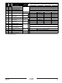
Comment
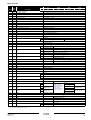
Address
Read/
Write
22
R/W
Inlet setpoint 1 Condensor
23
R/W
Inlet setpoint 2 Condensor
24
R/W
Step length inlet control
25
R/W
Step length outlet control
26
R/W
27
R
28
R
Description
Unit of
measurement
ER
EUWA
EUW
EUWL
**
ERAP
EWAP
EWWD
EWLD
Step difference outlet
Analog Output 1
Analog Output 2
V x 1/10
V x 1/10
29
R
Analog Output 3
V x 1/10
30
R
Analog Output 4
V x 1/10
31
R
Analog Output 5
V x 1/10
32
R
Analog Output 6
V x 1/10
33
R
Minimum outlet water
R
Heat recovery inlet
setpoint condensor(c)
34
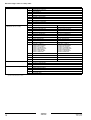
*
—
* —
** —
—
—
—
Fan inverter C1(a)
—
—
—
—
—
Fan inverter C2(a)(b)
—
—
** —
—
—
—
—
—
—
—
* —
—
—
—
* —
** —
* —
Fan inverter C1(a)
—
—
—
**
Fan inverter C2(a)(b)
—
—
** —
2 circuit units: C1 capacity feedback(b)
** —
2 circuit units: C2 capacity feedback(b)
°C x 1/10
Heat recovery inlet
difference condensor(c)
35
R/W
36
R
A11P: AI1
37
R
A11P: AI2
38
R
A11P: AI3
** —
39
R
A11P: AI4
** —
Ω x 1/10
(a) Only available if circuit has inverter fans
(b) Only available for units with 2 circuits
(c) Only for heat recovery units
EKAC200A
Address card
4PW14574-1B
Installation manual
9