1
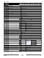
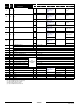
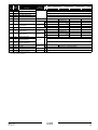
Digital variables
Comment
Address
Read/
Write
1
R
Description
*
ER
EUWA
EUW
EUWL
**
ERAP
EWAP
EWWD
EWLD
Unit status: monitoring
0 = Off, 1 = On
If 1 is written then toggle status of unit. (after this action the controller reset this parameter)
2
W
Unit status: control
3
R
Remote On/off enabled
0= No, 1 = Yes (Yes if changeable digital inputs ‘REMOTE ON/OFF" is selected)
4
R
General Alarm
0 = no alarm, 1 = alarm
5
R
General Unit alarm
0 = no alarm, 1 = alarm
6
R
General Circuit 1 alarm
0 = no alarm, 1 = alarm
7
R
General Circuit 2 alarm
0 = no alarm, 1 = alarm
8
R
—
—
9
R
General Network alarm
0 = no alarm, 1 = alarm
10
R
General Warning alarm
0 = no alarm, 1 = alarm
11
R
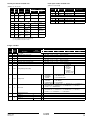
DI1 (0 = open, 1 = closed)
High pressure switch C1
12
R
DI2
Reverse phase protector C1
13
R
DI3
Overcurrent relay C1
14
R
DI4
Discharge thermal protector C1
15
R
DI5
Compressor thermal protector C1
16
R
DI6
Emergency stop
* Flowswitch
17
R
DI7
18
R
DI8
Changeable Input 1
19
R
DI9
Changeable Input 2
20
R
DI10
** Flowswitch
Flowswitch C1
Changeable Input 3
* Active 25% load(a)
Changeable Input 4
21
R
DI11
22
R
DI12
23
R
DI13
24
R
DI14
25
R
DI15
—
Discharge thermal protector C2(b)
26
R
DI16
—
Compressor thermal protector C2(b)
27
R
DI17
—
28
R
DI18
—
29
R
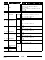
DO1
Compressor star C1
30
R
DO2
Compressor delta C1
31
R
DO3
Compressor on C1
32
R
DO4
33
R
DO5
34
R
DO6
35
R
DO7
36
R
DO8
** Changeable Input 4
* Active 40% load
** —
* Active 70% load
** —
* Active 100% load
** —
High pressure switch C2(b)
High pressure switch C2(b)
Reverse phase protector C2(b)
Reverse phase protector C2(b)
Overcurrent relay C2(b)
Overcurrent relay C2(b)
12% C1
* 40% C1
** —
* 70% C1
** —
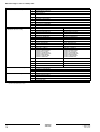
General situation of alarm
Air/water flowcontact Pump
*
R
DO9
38
R
DO10
39
R
DO11
40
R
DO12
Evaporator heatertape
41
R
DO13
Changeable output 2
42
R
DO14
—
Compressor star C2(b)
43
R
DO15
—
Compressor delta C2(b)
44
R
DO16
—
Compressor on C2(b)
45
R
DO17
—
12% C2(b)
46
R
DO18
* —
40% C2(b)
**
*
**
*
**
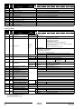
Fanstep 1 of C1
25% C1(a)
37
Fanstep 2 of C1
Fanstep 3 of C1
** —
Refer to "Detail
digital variables for
EUWA units", or to
"Detail digital
variables for EWAP
units" on page 5.
—
25% C2(a)(b)
—
70% C2(b)
—
Fanstep 1 of C1
Fanstep 2 of C1
Fanstep 3 of C1
Changeable output 1
—
(a) Only available if circuit has 25% capacity step.
(b) Only available for units with 2 circuits.
EKAC200A
Address card
4PW14574-1B
Installation manual
3