1
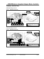
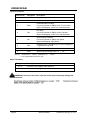
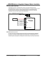
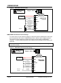
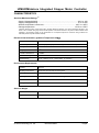
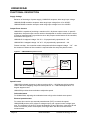
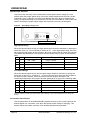
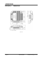
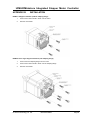
User Manual UIM243XXA/B Voltage Control Miniature Integrated Stepper Motor Controller UIM243XXA/B Please pay attention to the following before using the UIROBOT products: • • • UIROBOT products meet the specification contained in their particular Data Sheet. UIROBOT will only work with the customer who respects the Intellectual Property (IP) protection. Attempts to break UIROBOT’s IP protection feature may be a violation of the local Copyright Acts. If such acts lead to unauthorized access to UIROBOT’s IP work, UIROBOT has a right to sue for relief under that Act. Information contained in this publication regarding controller applications and the like is provided only for your convenience and may be superseded by updates. It is your responsibility to ensure that your application meets with your specifications. UIROBOT MAKES NO REPRESENTATIONS OR WARRANTIES OF ANY KIND WHETHER EXPRESS OR IMPLIED, WRITTEN OR ORAL, STATUTORY OR OTHERWISE, RELATED TO THE INFORMATION, INCLUDING BUT NOT LIMITED TO ITS CONDITION, QUALITY, PERFORMANCE, MERCHANTABILITY OR FITNESS FOR PURPOSE. UIROBOT disclaims all liability arising from this information and its use. Use of UIROBOT products in life support and/or safety applications is entirely at the buyer’s risk, and the buyer agrees to defend, indemnify and hold harmless UIROBOT from any and all damages, claims, suits, or expenses resulting from such use. No licenses are conveyed, implicitly or otherwise, under any UIROBOT intellectual property rights. [Trade Mark/ Layout-design/Patent] The UIROBOT name and logo are registered trademarks of UIROBOT Ltd. in the P.R. China and other countries. UIROBOT’s UIM24XXX series Step Motor Controllers, UIM25XX series CAN-RS232 Converter and their layout designs are patent protected. [ UIM243XXA/B Ordering Information ] In order to serve you quicker and better, please provide the product number in following format. UIM243XX PART NUMBERING SYSTEM UIM 2 4 3 Category Series Motor Control Voltage Control L 0 2 A P Control Connector T = Screw Terminal P = Plug / Socket Speed Control A = On-board Potentiometer B = Ext. Voltage / Potentiometer Peak Current 02 = 2A; Maximum Supply Voltage L = 35V; 04 = 4A; C =40V Examples: UIM243C04BP;UIM243L02B;UIM243L02AT Examples of Control Connector options: Screw Terminal Page 2 Rectangular Plug / Socket M432130405EN UI Robot Technology Co. Ltd UIM243Miniature Integrated Stepper Motor Controller UIM243XX A / B Voltage Control Miniature Integrated Stepper Motor Controller Miniature Integral Design Miniature size 42.3mm x 42.3mm x 16.5mm (L x W x H) Integrally designed to fit onto motors seamlessly, as well as work standalone Die-cast aluminum enclosure, improved heat dissipation and durability Motor Driver Features 10 - 40VDC *input voltage, Max 2A ~ 4A adjustable phase current 16th micro-stepping Dual full H-bridge with PWM constant current control *UIM243L02: 10 - 30VDC,UIM243C04: 10 – 40VDC Control Features Embedded microcontroller Self pulse generation, automatic run on power-up Speed control through on-board trimmer 0.15 - 1900 RPM (UIM243XXA) Speed control through external potentiometer 0.15 - 1900 RPM (UIM243XXB) Speed control through 0 - 5V voltage input 0.15 - 1900 RPM (UIM243XXB) 0.3 seconds acceleration period Switch control run/stop, direction, enable/shutdown Automatic current reduction / power saving GENERAL DESCRIPTION UIM243XXA/B stepper motor controller is a microprocessor embedded, voltage control, miniature stepper motor controller. UIM243XX is integrally designed to fit onto stepper motors, and is simple to control. With UIM243XXA/B, the motor speed can be controlled by an analog voltage. It is simple, stable and low cost. UIM24302 can provide 0 - 2A adjustable phase current through 10 ~ 30VDC input voltage. UIM24304 can provide 0 - 4A adjustable phase current through 10 ~ 40VDC input voltage. The microprocessor of the UIM243XXA/B is capable to ramp up the current speed to the desired speed. It is possible to jump to 1900 rpm in 0.3 seconds. This feature makes the sudden increase of the desired speed become possible. With the UIM243XX, the motor speed can be controlled by an analog voltage in three optional ways: 1) the on-board trimmer (UIM243XXA), 2) an external potentiometer (UIM243XXB) or, 3) an external voltage (UIM243XXB). UIM243XX controllers can run the motor without user control device. At the same time, with the high-speed current compensation function, UIM243XX can compensate the effects caused by counter electromotive force, which is produced in high-speed motor turning. UI Robot Technology Co. Ltd. M432130405EN Page3 UIM243XXA/B UIM243XX can be mounted onto NEMA 17 / 23 series stepper motor seamlessly through adapting flanges. The enclosure is made of die-cast aluminum which provides a rugged durable protection and improves the heat dissipation. Page 4 M432130405EN UI Robot Technology Co. Ltd UIM243Miniature Integrated Stepper Motor Controller TERMINAL DESCRIPTION UIM243XXA Wiring Terminal Figure0-1: UIM243XXA wiring terminal JumperJ1/J2 Va Measuring Current Trimmer Speed Trimmer 6 1 Motor A+ ABB+ V+ GND ENA ON H/L To avoid loss of terminal screws, please always keep screws tightened DIR Control UIM243XXB Wiring Terminal Figure0-2: UIM243XXB wiring terminal JumperJ1/J2 Va Measuring Current Trimmer 8 1 Motor A+ ABB+ V+ GND ENA ON H/L DIR Vr SPD Control UI Robot Technology Co. Ltd. M432130405EN To avoid loss of terminal screws, please always keep screws tightened Page5 UIM243XXA/B Control Terminals Terminal No. Designator Description 1 V+ Supply voltage 10 – 40 VDC* 2 GND Supply voltage ground ENA Enable/Disable H-bridge. Low-level (shorten to GND): rotor is in free state High-level/dangling: motor is in controlled state ON Run/Stop. Low-level (shorten to GND): motor is locked High-level/dangling: motor is in controlled state 5 H/L Speed Range selection. Low-level (shorten to GND): low speed High-level/dangling: high speed 6 DIR Direction input. Controlled by H/L level. Dangling is regarded as high level. 7 Vr 5V Reference Voltage output 8 SPD Speed Control Voltage input(0 – 5V) 3 4 NOTICE:* UIM243L02: 10 - 30VDC,UIM243C04: 10 – 40VDC Only UIM243XXB provides this port. Motor Terminals Designator Description A+ / A- Connect to the stepper motor phase A B+ / B- Connect to the stepper motor phase B WARNING:Incorrect connection of phase winds will permanently damage the controller! Page 6 M432130405EN UI Robot Technology Co. Ltd UIM243Miniature Integrated Stepper Motor Controller TYPICAL APPLICATION UIM24302A controller is equipped with a million-cycle speed adjusting trimmer. UIM24302B allows the user to use an external potentiometer or external voltage to control the speed. Run/stop, direction, high/low speed range and, enable/disable can be controlled simply by shorting the corresponding terminal to the ground. UIM24302 controllers can run the motor without user control device. Figure1-1: UIM243XXA using Onboard Trimmer Stepper Motor A+ A- 10 - 40VDC* Enable Run/Stop H/L Speed Direction 1 V+ 2 GND 3 ENA B- B+ UIM24302A Controller 4 ON/OFF 5 H/L 6 DIR Speed Trimmer * UIM243L02: 10 - 30VDC,UIM243C04: 10 – 40VDC UIM243XXB with External POT For users need to use external potentiometer (POT) to control the speed, UIM24302B provides a 5V reference voltage output, and a speed control voltage input port. The resistance of the POT should be between 5K and 10K ohms. Less than 5K will result in excessive power consumption, and larger than 10K will cause inaccurate measurement. UI Robot Technology Co. Ltd. M432130405EN Page7 UIM243XXA/B Figure1-2: UIM243XXB with External POT NEVER shorten Vr to GND Stepper Motor A+ A- 10 - 40VDC* Enable Run/Stop V+ 2 GND 3 ENA B- B+ UIM243XXB Controller 4 ON/OFF H/L Speed Direction 10K POT 1 5V Output Control Voltage 5 H/L 6 DIR 7 Vr 8 SPD * UIM243L02: 10 - 30VDC,UIM243C04: 10 – 40VDC UIM243XXB with External Control Voltage For users want to use an external voltage to control the speed to facilitate the needs such as microprocessor D/A control, UIM24302B provides a speed control voltage input port. The external control voltage must share the common ground with the UIM24302B controller. In other words, the ground of the external control voltage must be linked to the terminal 2 The external control range must between -0.3V and 5.3V. Voltage outside the range will only produce smoke. Figure1-3: UIM243XXB with External Control Voltage NEVER shorten Vr to GND Stepper Motor A+ A- B- B+ 1 V+ 10 - 40VDC* Enable Run/Stop H/L Speed External Voltage + Directio n Control Voltage 2 GND 3 ENA UIM243XXB Controller 4 ON/OFF 5 H/L 6 DIR 7 Vr 8 SPD * UIM243L02: 10 - 30VDC,UIM243C04: 10 – 40VDC Page 8 M432130405EN UI Robot Technology Co. Ltd UIM243Miniature Integrated Stepper Motor Controller CHARACTERISTICS Absolute Maximum Ratings (†) Supply Voltage(243L02)................................................................................. -0.3V to 30V Supply Voltage(243C04).................................................................................. -0.3V to 40V Ambient temperature under bias ................................................................ -40°C to +85°C Storage temperature.................................................................................. -50°C to +150°C †NOTICE: Stresses above those listed under “Absolute Maximum Ratings” may cause permanent damage to the device. This is a stress rating only and functional operation of the device at those or any other conditions above those indicated in the operation listings of this specification is not implied. Exposure to maximum rating conditions for extended periods may affect device reliability. Electrical Characteristics(Ambient Temperature 25℃) Supply Power Voltage 10 - 30VDC (243L02); 10 - 40VDC (243C04); Motor Output Current Max 2A per phase (Adjustable through on-board trimmer) Driving Mode PWM constant current Stepping Resolution 16 fixed Insulation Resistance >100MΩ Dielectric Strength 0.5KV in one minute Speed Range 8 Hz – 102K Hz, 0.15 - 1912.5 RPM (1.8°Motor) th Environment Requirements Cooling Free air Working environment Avoid dust, oil mist and corrosive gases Working temperature -40°C ~ 85°C Humidity <80%RH,no condensation, no frosting Vibration 3G Max Storage temperature -50°C ~ 150°C Size and Weight Size 42.3mm x 42.3mm x 16.5mm Wight 0.1 kg UI Robot Technology Co. Ltd. M432130405EN Page9 UIM243XXA/B FUNCTIONAL DESCRIPTION Supply Voltage Because of the design of power supply, UIM243XX accepts a wide range input voltage. UIM243L02A/B controller accepts a wide range input voltage from 10 to 30VDC. UIM243C04A/B controller accepts a wide range input voltage from 12 to 40VDC. Output Phase Current UIM243XX is capable of providing a maximum 2A / 4A phase output current. In specific application, the peak output current needs to be adjusted to meet the rated motor current. A trimmer (potentiometer) is provided to serve this purpose at the bottom of the controller, as shown in the figure 3-1. UIM243L02: A mapped voltage “Va” of 0 - 4V proportionally represents 0 ~ 2A. UIM243C04: A mapped voltage “Va” of 0 - 4V proportionally represents 0 ~ 4A. Please note that,the controller needs to be powered before mapped voltage “Va” can be measured. Reboot of the controller is required after the setup the phase current. Figure3-1: UIM243XXB Setup Phase Current 10 - 30VDC Volt Meter Current Adjusting Trimmer Mapped Voltage Va Speed Control UIM243XX onboard processor is able to produce 8 Hz – 102 KHz step driving pulses. Under 16th micro stepping, that pulse rate equal to 0.15 – 1900 RPM speed for a 1.8 degree stepper motor. UIM243XX provides three methods to adjust the speed: Onboard trimmer For UIM243XXA, adjusting the onboard trimmer will give the desired motor speed. External potentiometer For users who need to use external potentiometer (POT) to control the speed, UIM243XXB provides a 5V reference voltage output, and a speed control voltage input port. The resistance of the POT should be between 5K and 10K ohms. Less than 5K will result in excessive power consumption, and larger than 10K will cause inaccurate measurement. Page 10 M432130405EN UI Robot Technology Co. Ltd UIM243Miniature Integrated Stepper Motor Controller External control voltage For users want to use an external voltage to control the speed to facilitate the needs such as microprocessor D/A control, UIM243XXB provides a speed control voltage input port. The external control voltage must share the common ground with the UIM243XXB controller. In other words, the ground of the external control voltage must be linked to the terminal 2. In addition, the external control range must between -0.3V and 5.3V. Voltage outside the range will only produce smoke. UI Robot Technology Co. Ltd. M432130405EN Page11 UIM243XXA/B Speed Range Selection To preserve the accuracy of the measurement of the speed control voltage, the user should select the proper speed range. Since the voltage measurement accuracy is 8bit, (UIM243XX uses a 10bit A/D converter, and abandon the last 2 digits to suppress the noise), the speed adjusting is not continuous, but has an incremental of 1/255 of the max speed. Selecting the proper speed range can improve the accuracy of the speed. Figure3-2: Speed Range Jumper J1/J2 J2 J1 Speed Range Jumpers High Speed Range When the desired speed is high, the high speed range should be selected, by leaving the terminal 5 open (i.e., not connected) or linking to 5V. In the high speed range, there are two jumpers at the bottom of the controller, which can further limit the range of the speed. The relationship between the two jumpers and the speed range is given in the following table: J1 J2 Note Pulse Frequency(Hz) Speed for 1.8o stepper(RPM) open open 100 - 102K 1.875 – 1912.5 short short 100 - 102K 1.875 – 1912.5 open short 100 - 51K 1.875 – 956.25 short open 100 – 25.5K 1.875 – 478.125 Factory Defauilt Low Speed Range When the desired speed is low, the low speed range should be selected, by linking the terminal 5 to ground (i.e., terminal 2). In the low speed range, there are two jumpers at the bottom of the controller, which can further limit the range of the speed. The relationship between the two jumpers and the speed range is given in the following table: J1 J2 Note Pulse Frequency(Hz) Speed for 1.8o stepper(RPM) open open 8 – 8.16K 0.15 – 153 short short 8 – 8.16K 0.15 – 153 open short 8 – 4.08K 0.15 – 76.5 short open 8 – 1.04K 0.15 – 38.25 Factory Defauilt NOTICE: Please provide your speed range when ordering, if you want the jumpers to be set by the factory. Acceleration Deceleration The microprocessor of the UIM24302A/B is capable to ramp up the current speed to the desired speed in 0.3 seconds, even when the speed control voltage is changing. This feature makes the sudden increase of the desired speed become possible. Page 12 M432130405EN UI Robot Technology Co. Ltd UIM243Miniature Integrated Stepper Motor Controller To guarantee the motor can stop as quicker as possible, the deceleration rate is set to infinity, which means the motor will output a desired speed (lower than current speed) immediately. UI Robot Technology Co. Ltd. M432130405EN Page13 UIM243XXA/B APPENDIX A DIMENSIONS Units: mm Page 14 M432130405EN UI Robot Technology Co. Ltd UIM243Miniature Integrated Stepper Motor Controller APPENDIX B INSTALLATION NEMA 17 Stepper Installation (without adapting flange) 1. Screw mount UIM controller / driver onto the motor 2. Wire the motor leads. NEMA 23 and Larger Stepper Installation (with adapting flange) 1. Screw mount the adapting flange onto the motor 2. Screw mount UIM controller / driver onto the adapting flange 3. Wire the motor leads. UI Robot Technology Co. Ltd. M432130405EN Page15


![[U4.44.22] Opérateur MODI_OBSTACLE](http://vs1.manualzilla.com/store/data/006356813_1-2c70d2f06f0b16eeac21e0f75900d7cc-150x150.png)