1
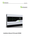
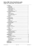
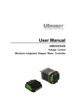
Use er M Manu ual U UIM290 01-5A MACH3 Brea akout Board B UIM2901-5A Please pay attention to the following before using the UIROBOT products: • UIROBOT products meet the specification contained in their particular Data Sheet. • UIROBOT will only work with the customer who respects the Intellectual Property (IP) protection. • Attempts to break UIROBOT’s IP protection feature may be a violation of the local Copyright Acts. If such acts lead to unauthorized access to UIROBOT’s IP work, UIROBOT has a right to sue for relief under that Act. Information contained in this publication regarding controller applications and the like is provided only for your convenience and may be superseded by updates. It is your responsibility to ensure that your application meets with your specifications. UIROBOT MAKES NO REPRESENTATIONS OR WARRANTIES OF ANY KIND WHETHER EXPRESS OR IMPLIED, WRITTEN OR ORAL, STATUTORY OR OTHERWISE, RELATED TO THE INFORMATION, INCLUDING BUT NOT LIMITED TO ITS CONDITION, QUALITY, PERFORMANCE, MERCHANTABILITY OR FITNESS FOR PURPOSE. UIROBOT disclaims all liability arising from this information and its use. Use of UIROBOT products in life support and/or safety applications is entirely at the buyer’s risk, and the buyer agrees to defend, indemnify and hold harmless UIROBOT from any and all damages, claims, suits, or expenses resulting from such use. No licenses are conveyed, implicitly or otherwise, under any UIROBOT intellectual property rights. [Trade Mark/ Layout-design/Patent] The UIROBOT name and logo are registered trademarks of UIROBOT Ltd. in the P.R. China and other countries. UI Robot Technology Co. LTD M2901110822EN Page | 2 UIM2901-5A MACH3 Breakout Board UIM2901-5A MACH3 breakout board FEATURES General DB25 interface between PC and user device Fully buffered opto-isolated I/O (Input / Output) Ports Motor Driving Output Support 5 stepping motor simultaneously, X’, X, Y, Z, A Hardware generate secondary X' step/direction from X step/direction for Gantry System Jumper selectable, X' direction same / different from X direction Input Signals ESTOP hardware logic to disable servo drives and Charge Pump Limit switch inputs, X, Y, Z, A Jumper selectable anti-noise low pass filter Output Signals Up to 3+ Open-Drain outputs could be extended for Flood/Mist/ATC etc Charge Pump relay, 2 normal open, 2 normal close, 30VDC, 2Amp Isolated PWM analog output signal for spindle speed control CHARACTERISTICS Absolute Maximum Ratings PC Side Supply Voltage................................................................................................................ 5.5V Switch Side Supply Voltage.......................................................................................................12.5V Ambient temperature under bias…………….................................................................. -40° to +85°C Storage temperature.................................................................................................... -50° to +125°C Recommended Working Conditions(Ambient Temperature 25℃) Supply Voltage 5VDC (PC Side) and 12VDC (Switch Side) Cooling Free Air Working Environment Environment Avoid dust, oil mist and corrosive gases Temperature -40 ℃ - + 85 ℃ Humidity <80%RH,no condensation, no frosting Vibration 3G Max Storage Temperature -40 ℃ - + 125 ℃ Size 110mm x 90mm x 15mm (L x W x H) Wight 0.15 kg Page | 3 M2901110822EN UI Robot Technology Co. LTD UIM2901-5A TYPICAL WIRING SCHEMATIC A typical wiring schematic diagram is provided in Figure 0-1. Although it is designed for UIM240xx Stepper Motor Driver, it may be used for other stepper motor drivers. User control devices (such as PC) connect to the UIM2901-5A through a male to male DB25 cable. The logic side (user device side) electronics are powered by either a USB cable or a standalone 5VDC power supply. A 12VDC power supply is required if the user wants to use the Relay, Limit Switches, EMS Switch and/or other machine side electronics. There are opto-isolators between the logic side and the machine side. Please note, the 12V power supply is NOT requireded, if only the UIM240xx Stepper Motor Drivers are connected (i.e., not using other switches or functions like spindle control, etc.). Figure 0-1: Typical wiring schematic Computer DB25 Cable (M/M) External Power 12V USB Cable Limit Switch Spindle Limit Switch Digital Ground FWD/Stop ACM: Analog Ground AVI : Analog Input +10V: Provided by VFD EM Stop VFD Spindle Drive Stepper Power 12V – 40V UIM240 Stepper Driver UI Robot Technology Co. LTD UIM240 Stepper Driver M2901110822EN Page | 4 UIM2901-5A MACH3 Breakout Board 1.0 I/O Ports and Jumper Settings To help users clearly understand the operation/configuration of the UIM2901-5A Breakout Board, schematic drawings of the board are provided below. Please note, the jumpers’ orientation/direction is the same as that on the PCB. 1.1 DB25 Connector Schematic UIM2901-5A uses a male to male DB25 cable to communicate with the MACH3 software. The definition of each PIN is provided in the Figure 1-1. Al input signals are opto-isolated and buffered. All Output signals are buffered and opto-isolated either by the UIM2901-5A Board or by the UIM240xx Stepper Drivers. If the upper two pins of JP1 is shorten, Axis X’ and Axis X running direction will be opposite. If the lower two pins of JP1 is shorten, Axis X’ and Axis X running direction will be the same. Figure 1-1 DB25 Connector Schematic Page | 5 M2901110822EN UI Robot Technology Co. LTD UIM2901-5A 1.2 Motor and Charge Pump Control Circuit By shorting the left two pins (near the mark of JP2/JP3) of both JP2 and JP3, MACH3’s Charge Pump feature can be enabled. Charge Pump action will disable all UIM240 Stepper Drivers and the Charge Pump relay, which can cause stepper motors and spindle to stop. Shorting the right two pins of JP2 and JP3, the Charge Pump feature will be disabled. Signal from the PIN17 can be used to control the open-collector output of P17C and P17E. Figure 1-2 Motor and Charge Pump Control Circuit 1.3 Digital Input and Output Circuit By shorting the left two pins (near the legend of JP5/JP6) of both JP5 and JP6, the onboard relay can be enabled and controlled through DB25 pin 17. Pin 16 can be used as open-collector control output. Please note that, P16C links to the opto-isolator’s collector pin and the P16E links to the emitter pin. UI Robot Technology Co. LTD M2901110822EN Page | 6 UIM2901-5A MACH3 Breakout Board Figure 1-3 Digital Input and Output Circuit 1.4 Spindle Control Circuit By shorting the left two pins (near the legend of JP7/JP8) of both JP7 and JP8, a PWM wave will be generated to provide a voltage used to control the spindle speed. Figure 1-4 Spindle Control Circuit Page | 7 M2901110822EN UI Robot Technology Co. LTD UIM2901-5A 1.5 Digital Input Filters By shorting the four sets pins of JP4, the hardware digital input filter can be enabled. If JP4 is left open, the digital inputs can be used for high speed inputs. Please note, in either situation, input signals are opto-isolated from the user control device such as the computer. Figure 1-5 Spindle Control Circuit UI Robot Technology Co. LTD M2901110822EN Page | 8 UIM2901-5A MACH3 Breakout Board 2.0 MACH3 Configuration For the UIM2901-5A to work properly, following MACH3 software configuration should be made. 2.1 Port Setup Refer to the MACH3 USER MANUAL for how to determine the proper address here. 2.2 Motor Driving Step and Direction Configuration Page | 9 M2901110822EN UI Robot Technology Co. LTD UIM2901-5A 2.3 Limit Switch Configuration 2.4 Emergency Stop Switch Configuration UI Robot Technology Co. LTD M2901110822EN Page | 10 UIM2901-5A MACH3 Breakout Board 2.5 Motor Drive Enable Feature Configuration 2.6 Charge Pump Feature Configuration Page | 11 M2901110822EN UI Robot Technology Co. LTD UIIM2901--5A 2.7 Sp pindle mo otor speed contrrol If y you use the MACH3 M the milling m modu ule, the spind dle motor speed control p panel buttons do no ot. For the sp pindle motor speed can b be controlled by programm ming (G cod de or M code) to hieve. The fo ollowing outlines the met hods to achieve. ach 1) Open MACH3 milling mo odule. he spindle motor m control pin. 2) Configure th Cliick map pins s configured Spindle. No ote also sure to JP7/JP8 jumper shortted the PWM stage (see Figur re 2-4,1.4 seection). Aftter Click “Apply” 3) Configu ure the spindle e motor contro ol parameters. . In the Spin ndle Setup page, press the red box param meters Figure fill. After Click “Apply” UI Robott Technology Co. LTD M2901110 0822EN Page | 12 UIM M2901-5 5A MAC CH3 Bre eakout Board B 4) Con nfigure the motor pulley spindle speed. Click m map tips, click SSpindle Pulleys.. In the pop‐up Pulley Selectio on dialog box, fill in parameterss as illustrated. 5) Con nnect the test circuit. Conneection as PC, an n external 12V p power supply, eexternal 10V po ower supply and d connected to o the external ta able Spindle units o out and 0V term minal port. DB25 数据线(M//M) Power Inputt 12V PC USB Communication W Wire Multimetter for Voltage Pow wer Supply DC C 10V Page | 13 M M290111082 22EN UI Roboot Technology y Co. LTD UIM2901-5A 6) Test the spindle motor speed control. Click on manual data input button on the control interface, fill in the input box: G96 S500 (S preceded by a space), Enter to confirm input. Then click the Spindle CW button. Please note that clicking the Spindle CW button, make sure the system is not in emergency stop state (ie, emergency stop button is not flashing). Then Spindle wiring sets the output voltage should be around 5V. Input on the control interface box filled: G96 S900, Enter to confirm input. Spindle wiring sets the output voltage should be around 9V. Input on the control interface box filled: G96 S100, Enter to confirm input. Spindle wiring sets the output voltage should be about 1V. Input on the control interface box filled: G96 S700, Enter to confirm input. Spindle wiring sets the output voltage should be around 7V. Since the PWM signal into a voltage signal, the line will be in the diode voltage drop of about 0.5V, so the nominal 9V voltage, measured at around 9.3 ~ 9.5V, 1V nominal voltage, measured at around 1.3 ~ 1.5V 7) access frequency spindle drive. Figure 0‐1 the frequency spindle drive access UIM2901. 8) programming control. G code or M code programming (such as the aforementioned G96 S500) control in order to achieve frequency spindle drive spindle speed control. UI Robot Technology Co. LTD M2901110822EN Page | 14 UIM2901-5A MACH3 Breakout Board APPENDIX A DIMENSIONS 4x 3.6 80 90 5 5 100 110 Units: mm Page | 15 M2901110822EN UI Robot Technology Co. LTD