1
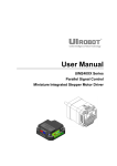
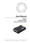
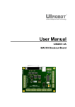
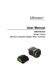
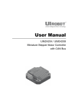
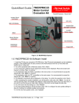
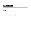
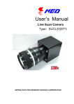
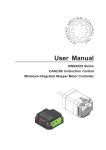
User Manual UIM240XX Series Parallel Signal Control Miniature Integrated Stepper Motor Driver UIM24002/04/08 Please pay attention to the following before using the Mach Motion products: - Mach Motion products meet the specification contained in their particular Data Sheet. - Mach Motion wil only work with the customer who respects the Intellectual Property (IP) protection. - Attempts to break Mach Motion’s IP protection feature may be a violation of the local Copyrights Acts. If such acts lead to unauthorized access to Mach Motion’s IP work, Mach Motion has a right to sue for relief under that Act. Information contained in this publication regarding controller applications and the like is provided only for your convenience and may be superseded by updates. It is your responsibility to ensure that your application meets with your specifications. Mach Motion makes no representations or warranties fo any kind wether express or implied, written or oral, statutory or otherwise, related to the information, including but not limited to its condition, quality, performance, merchantability or fitness for purpose. Mach Motion disclaims all liability arsing from this information and its use. Use of Mach Motion products in life support and/or safety applications is entirely at the buyer’s risk, and the buer agrees to defend, indemnify and hold harmless Mach Motion from any and all damages, claims, suits, or expenses resulting from such use. No licenses are conveyed, implicitly or otherwise, under any Mach Motion intellectual property rights. [Trade Mark/ Layout-design/Patent] The UIROBOT name and logo are registered trademarks of UIROBOT Ltd. in the P.R. China and other countries. UIROBOT’s UIM24XXX series Step Motor Controllers, UIM25XX series CAN-RS232 Converter and their layout designs are patent protected. [UIM240XX Ordering Information] In order to serve you quicker and better, when you order UIM240XX series controller, please provide the product number in following format. UIM240XX PART NUMBERING SYSTEM UIM - 2 4 0 - Category Series Current Control Connector UIM Motor Control 240 Parallel signal 02 = 2A 04 = 4A 08 = 8A T = Screw Terminal P = Plug / Socket Custom Note: Optional. Default control connector is T (screw terminal) if not selected. Examples: UIM24004, UIM24004P, UIM24008P, etc. Examples of Control Connector options: Screw Terminal Mach Motion Products Rectangular Plug / Socket Page 2 UIM240XX Miniature Integrated Stepper Motor UIM24002/24004/24008 Parallel Signal Control Miniature Integrated Stepper Motor Driver FEATURES Miniature size 42.3mm*42.3mm*16.5mm Integral design Wide range input voltage 10-40VDC 0 - 2A / 1.5 - 4A / 3 - 8A adjustable output current 1 to 16th micro stepping Automatic Current Reduction Dual full H-bridge with PWM constant current control Enable/shutdown input for power saving Optical-isolated inputs Die-cast aluminum enclosure DESCRIPTION UIM240XX Miniature Stepper Motor Drivers are series miniature, high performance stepper motor controllers. They can be mounted onto NEMA 17 / 23 / 34 / 42 series stepper motor seamlessly through corresponding flanges. The thickness of these controllers is less than 15 mm. The UIM24002 outputs 0-2A adjustable current, the UIM 24004 outputs1.5-4A adjustable current and the UIM24008 outputs 3-8A adjustable current. Their mixed-decay current control reduces the backEMF effect under high motor speed and improves the performance. Except that UIM24002 takes 1035VDC input, UIM240XX series controllers work on 12 - 40VDC input. The enclosure is made of die-cast aluminum which provides a rugged, durable protection and improves the heat dissipation. Mach Motion Products Page 3 UIM24002/04/08 TERMINAL DESCRIPTION Figure 0-1: Wiring Terminal Current Adjusting Trimmer Current Measurement Pads DIP Switch2 DIP Switch1 Motor Terminal BB+ A+ AV+ GND VCC DIR STP To avoid loss of screws, please always keep screws tightened. ENA Control Terminal Control Terminals Terminal No. Designator Description 1 V+ Supply voltage, 12 - 40VDC 2 GND Supply voltage ground 3 VCC Opto-coupler common anode 4 DIR Direction input(1) 5 STP Stepping pulse input(2) 6 ENA Enable the controller(3) Note: (1) Input is considered high level if this terminal is not connected. (2) Low-level pulse duration should > 4μs. (3) An active low-level input shuts down power supply to the motor. High-level input or left open makes the controller fully working. When awaken from shutdown mode, wait 1 millisecond before sending pulse. Motor Terminals Terminal No. Designator Description 1/2 A+ / A- Connect to the stepper motor phase A 3/4 B- / B+ Connect to the stepper motor phase B Warning: Incorrect connection of phase winds will permanently damage the controller. Resistance between leads of different phases is usually > 100K . Resistance between leads of the same phase is usually < 100 . Mach Motion Products Page 4 UIM240XX Miniature Integrated Stepper Motor TYPICAL APPLICATION UIM240xx controller’s wiring is very straightforward as shown in following Figure. Terminal 6 (EN) can be left open if offline is not needed. Figure 0-2: Typical Application Stepper Motor A+ 12 ~ 40VDC 3.3~5V A- B- B+ 1 V+ UIM240XX 2 GND VCC 3 VCC 499 User MCU Direction 4 Pulse DIR 5 STP Enable 6 ENA OPTICALLY ISOLATED INPUT INTERFACE UIM240xx controllers’ logic control inputs are all optically isolated. All opto-isolators share one common anode (VCC) as shown in above schematic diagram. Typically, VCC is 5V. However, 3.3V or voltages higher than 5V are also acceptable, so long as the current through the opto-isolator’s emitter is between 5~20mA. Should a voltage higher than 5V be applied to VCC, an additional resistor is needed for every terminal to ensure that the current through each emitter does not exceed 20mA. Figure 0-3: Optically Isolated Input Interface 3.3-24V 3 UIM240XX VCC 500Ω User Device Additional Resistor STP, DIR, etc. X 5~20mA Note, in most situations, VCC can also be used as common cathode connection. This is because the opto-isolators used in UIM240 are bidirectional (AC&DC) type. Mach Motion Products Page 5 UIM24002/04/08 CHARACTERISTICS Absolute Maximum Ratings (†) Supply Voltage......................................................................................................................... 10V to 40V Ambient temperature under bias……………...................................................................... -40°C to +85°C Storage temperature........................................................................................................ -50°C to +150°C †NOTICE: Stresses above those listed under “Absolute Maximum Ratings” may cause permanent damage to the device. This is a stress rating only and functional operation of the device at those or any other conditions above those indicated in the operation listings of this specification is not implied. Exposure to maximum rating conditions for extended periods may affect device reliability. Electrical Characteristics (Ambient Temperature 25°C) Supply Power Voltage 12 – 40VDC (10 – 35VDC for UIM24002) Motor Output Current Max 2A/4A/8A per phase (Adjustable through on-board trimmer) Driving Mode PWM constant current Stepping Resolution Full, 1/2 step, 1/4 step, 1/8 step, and 1/16 step Insulation Resistance >100MΩ Dielectric Strength 0.5KV in one minute Communication (Ambient Temperature 25°C) Parallel Communication 3-wire interface: Pulse, Direction, Shutdown Micro Step Resolution 1, 1/2, 1/4, 1/8, 1/16 set through on-board DIP switch 1 and switch 2 Environment Requirements Cooling Free air Working environment Avoid dust, oil mist and corrosive gases Working temperature -40°C ~ 85°C Humidity <80%RH,no condensation, no frosting Vibration 3G Max Storage temperature -50°C ~ 150°C Size and Weight Size 42.3mm x 42.3mm x 16.5mm (L*W*H) Wight 0.1 kg Mach Motion Products Page 6 UIM240XX Miniature Integrated Stepper Motor FUNCTIONAL DESCRIPTION Supply Voltage UIM240xx controllers accept a wide range input voltage from 12 to 40VDC. (UIM24002 takes 10 – 35 VDC) In general, higher supply voltage improves motor performance under high speed situation, but also increases the power loss and temperature raise. Automatic Current Reduction (ACR) UIM240XX controller is featured of Auto Current Reduction. If this function is enabled, when the motor stops running, the phase current will be cut to 50% of the set value. As soon as the motor goes back to working, the current will go back to the set value. This function is enabled by turn the DIP1 (figure 0-4) of the DIP switch 2 to the ON position. Adjust Output Current UIM24002/04/08 is capable of providing maximum2A / 4A / 8A per phase output current respectively. In specific application, the peak output current needs to be adjusted to meet the rated motor current. A trimmer (potentiometer) is provided to serve this purpose at the bottom of the controller, as shown in the following figure. Measuring the mapped voltage (Va) when tuning the trimmer provides a easy way to set the output current. For UIM24002, a mapped voltage “Va” of 0 - 2V proportionally represents 0 ~ 2A. For UIM24004, a mapped voltage “Va” of 0 - 4V proportionally represents 0 ~ 4A. For UIM24008, a mapped voltage “Va” of 0 - 4V proportionally represents 0 ~ 8A. Note: 1. 2. 3. The controller needs to be powered before mapped voltage “Va” can be measured. (Motor is not required to be connected at this time.) DIP1 (on the bottom side DIP switch 2) needs to be turned off to shut down the ACR Function. After adjustment, user can choose to turn on the DIP1 to enable the automatic current reduction. Figure 0-4: Adjusting the Output Current Bottom Side 12 ~ 40VDC Voltmeter Mapped Voltage Va Before measuring Va: 1) Apply Power 2) Turn off DIP1 Current Adjustment Trimmer Micro Stepping Resolution The micro stepping resolution is set by both DIP switch 1 and DIP switch 2 located at top and bottom side of the driver as shown in following figure. UIM240xx controller can provide micro-stepping control at full-step, 1/2, 1/4, 1/8 and 1/16 step resolutions. Full Resolution 1/2 1/8 1/4 1/16 DIP Switch 1 1 2 ON 1 2 ON 1 2 ON 1 2 ON 1 2 ON DIP Switch 2 1 2 ON 1 2 ON 1 2 ON 1 2 ON 1 2 ON Mach Motion Products Actuator For ACR use Page 7 UIM24002/04/08 APPENDIX A DIMENSIONS Units: mm Mach Motion Products Page 8 UIM240XX Miniature Integrated Stepper Motor APPENDIX B INSTALLATION NEMA 17 Stepper Installation (without adapting flange) 1. Screw mount UIM controller / driver onto the motor 2. Wire the motor leads. NEMA 23 and Larger Stepper Installation (with adapting flange) 1. Screw mount the adapting flange onto the motor 2. Screw mount UIM controller / driver onto the adapting flange 3. Wire the motor leads. Mach Motion Products Page 9