1
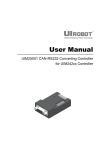
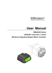
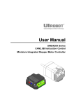
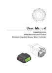
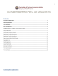
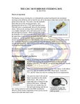
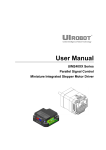
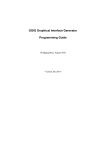
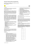
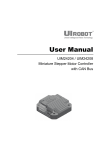
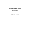
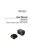
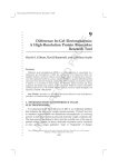
User Manual
UIM2501
CAN2.0B / RS232
Control Protocol Converter
Myostat Motion Control Inc. • www.myostat.ca • +1 905 836 4441
UIM2501 CAN/RS232 Control Protocol Converter
Please pay attention to the following before using the UIROBOT products:
• UIROBOT products meet the specification contained in their particular Data Sheet.
• UIROBOT will only work with the customer who respects the Intellectual Property (IP) protection.
• Attempts to break UIROBOT’s IP protection feature may be a violation of the local Copyright Acts. If such acts lead to
unauthorized access to UIROBOT’s IP work, UIROBOT has a right to sue for relief under that Act.
Information contained in this publication regarding controller applications and the like is provided only for your convenience
and may be superseded by updates. It is your responsibility to ensure that your application meets with your specifications.
UIROBOT MAKES NO REPRESENTATIONS OR WARRANTIES OF ANY KIND WHETHER EXPRESS OR IMPLIED,
WRITTEN OR ORAL, STATUTORY OR OTHERWISE, RELATED TO THE INFORMATION, INCLUDING BUT NOT LIMITED
TO ITS CONDITION, QUALITY, PERFORMANCE, MERCHANTABILITY OR FITNESS FOR PURPOSE. UIROBOT
disclaims all liability arising from this information and its use. Use of UIROBOT products in life support and/or safety
applications is entirely at the buyer’s risk, and the buyer agrees to defend, indemnify and hold harmless UIROBOT from any
and all damages, claims, suits, or expenses resulting from such use. No licenses are conveyed, implicitly or otherwise, under
any UIROBOT intellectual property rights.
[Trade Mark/ Layout-design/Patent]
The UIROBOT name and logo are registered trademarks of UIROBOT Ltd. in the P.R. China and other countries.
UIROBOT’s UIM24XXX series Step Motor Controllers, UIM25XX series CAN-RS232 Converter and their layout designs are
patent protected.
[UIM2501 Ordering Information]
In order to serve you quicker and better, please provide the product number in following format.
UIM2501 PART NUMBERING SYSTEM
UIM
Note:
2
5
0
Category
Series
UIM
Motor
Control
2501
CAN/232
Converter
1
Control
Connector
T = Screw Terminal
P = Plug / Socket
If not selected, default control connector is T (screw terminal), the code box can be deleted.
Examples: UIM2501P, UIM2501
M501110926EN Page 2
UI Robot Technology Co. Ltd
UIM2501
UIM2501
CAN/RS232 Control Protocol Converter
(For UIM242 Stepper Controller and UID820 CAN Digital I/O Controller)
FEATURES
Embedded DSP Microprocessor
Embedded high-performance DSP
Simple, intuitive, rich instructions
Intelligent, fault-tolerating, user-friend interface
MS Windows based VB / VC demo software and corresponding source code provided
RS232 Communication
RS232 three wire serial communication
CAN2.0B Active Communication
2-wire interface
Support 1M bps, long distance
Differential data bus, high noise immunity
Wide Supply Voltage
Wide supply voltage range from 6 40VDC
GENERAL DESCRIPTION
The UIM2501 RS232-CAN Converting Controller is used in conjunction with UIM242XX stepper motor
controller to provide a RS232 interface on the user side and a CAN bus interface on the motor side
(factory side).
With the UIM2501, user will be benefited from the advantages of the CAN network and the simplicity of
RS232 protocol, and no need to deal with the complicated CAN protocol, no worry about the
communication distance and noise immunity.
One UIM2501 controller can network with up to 100 UIM242XX controllers. Interfacing the UIM2501 is
simple, intuitive and fault tolerating. Users are not required to have stepper motor driving or CAN
protocol knowledge.
UIM2501 is compact in size. The enclosure is made of die-cast aluminum to provide a rugged durable
protection and improves the heat dissipation.
UI Robot Technology Co. Ltd.
M501110926EN Page 3
UIM2501 CAN/RS232 Control Protocol Converter
TERMINAL DESCRIPTION
Figure 0-1: Terminal Description
CANL
CANH
RS232
DB9
GND
V+
To avoid loss of terminal
screws, please always
keep screws tightened.
DIP Switch
Description of Screw Terminals
Terminal No.
Designator
Description
1
V+
Supply voltage, 12 - 40VDC
2
GND
Supply voltage ground
3
CANH
CAN Dominant High
4
CANL
CAN Dominant Low
RS232 Connector
DB-9 (Female Pin) connector
DIP SWITCH
UIM2501 controller has an 8-bit DIP switch, which serves multiple functions. When powering up,
DIP1~DIP7 are read as the UIM2501 controller’s ID/address. After powering up, DIP1 and DIP2 are
assigned to other RS232 related features (refer to the “RS232 communication” section).
DIP8 is used to enable the built-in terminating resistor.
Unless necessary, please maintain the DIP positions as shown in following Figure.
Figure 0-2: Terminal Description
Actuator
Controller ID
Terminating Resistor Enable
M501110926EN Page 4
UI Robot Technology Co. Ltd
UIM2501
TYPICAL APPLICATION
UIM2501 converter can work with one UIM242 or UID820 controller or a set of UIM242 and UID820
controllers in a CAN network. Typical applications are described below.
Single Slave Operation
If only one UIM242 or UID820 is used, following wiring scheme (figure 0-3) can be applied. For the
wiring scheme of UID820 digital IO controller, please refer to the UID820 user manual.
Please note that, this wiring scheme is mandatory when assigning a controller ID to a UIM242 controller
(motor is not required). Details are provided in Section 4.1.
Please note: Both ends of the CAN bus should be terminated with120 terminating resistors. As
UIM2501 converter has a build-in terminating resistor. To enable the terminating resistor, simply toggle
the DIP8 to the ON position. On the UIM242 controller side, user needs to attach a resistor to the end of
the bus as shown in figure 0-3.
Furthermore, CANH and CANL should be a twisted wire pair.
Figure 0-3: Wiring Scheme for Standalone Operation
Stepper Motor
6 – 40V
DC Supply
12 - 40V
DC Supply
1
2
UIM2501
Converter
3
4
CANH
120
CANL
Twist Wire Pair
1 V+
A+ A- B- B+
2 GND
3 CANH
4 CANL
5 AG
DB9 Port
RS232 Cable
6 S1
7 S2
8 S3
9 P4
UI Robot Technology Co. Ltd.
UIM242XX
Controller
M501110926EN Page 5
UIM2501 CAN/RS232 Control Protocol Converter
Network Operation
Multiple UIM242 and UID820 controllers can be wired together to form a reliable CAN control network.
Following figure provides a typical network wiring solution.
Figure 0-4: Wiring Scheme for Network Operation
Control Room
RS232
CANH
UIM2501
CANL
6-40
VDC
Plant
12-40
VDC
UIM242xx
Motor# 1
CANH
Stub length < 2cm
12-40
VDC
CANL
120
UIM242xx
Motor# 2
12-40
VDC
UIM242xx
Motor# 100
Please be aware that:
In multi-node CAN applications, it is important to maintain a direct point-to-point wiring scheme. A single
pair of wires should connect each element of the CAN bus, and the two ends of the bus should be
terminated with 120 resistors. A star configuration should never be used.
UIM2501 converter has a build-in terminal resistor. To enable the UIM2501 converter’s terminating
resistor, please toggle the DIP8 to ON position. User only needs to attach a resistor at the UIM242 end
of the bus.
In addition, any deviation from the point-to-point wiring scheme creates a stub. The high-speed edge of
the CAN data on a stub can create reflections back down the bus. These reflections can cause data
errors by eroding the noise margin of the system. Although stubs are unavoidable in a multi-node
system, care should be taken to keep these stubs as small as possible.
M501110926EN Page 6
UI Robot Technology Co. Ltd
UIM2501
INSTRUCTION SET SUMMARY
Instruction
Description
Feedback
Header
Message
ID
MDL=X;
Check the Model / Modules / Firmware of node x
0xCC
0xDE
MDL;
Check the Firmware Version of UIM2501
0xCC
0xDE
BDR=X;
Set RS232 baud rate
0xAA
0xBD
BTR=X;
Set CAN network communication bit rate index x
0xAA
0xBC
BTR;
Check current CAN network bit rate index
0xAA
0xBC
SETADR=X;
Assign an ID x to a UIM242XX controller
0xAA
0xDD
ADR=X;
Specify the operation object by node ID x
0xAA
0xD0
gREG;
Record the quantity of all subsidiary nodes and IDs
0xCC
0xD0
gENA;
Enable the H-Bridges of all nodes
0xAA
0xAD
gOFF;
Disable the H-Bridge of all nodes
0xAA
0xAD
gCUR=X;
Set motor phase current for all nodes
0xAA
0xAD
gACR=X;
Enable/disable the ACR function of all nodes
0xAA
0xAD
gMCS=X;
Set micro-stepping resolution for all nodes
0xAA
0xAD
gDIR=X;
Set desired motion direction for all nodes
0xAA
0xAD
gORG;
Set Original Point of all nodes
0xCC
0xAD
gSPD=X;
Set motor speed for all nodes
0xAA
0xAD
gSTP=X;
Setup relative position control for all nodes
0xAA
0xAD
gPOS=X;
Setup absolute position control for all nodes
0xAA
0xAD
gQEC=X;
Setup encoder based position control for all nodes
0xAA
0xAD
gDOUT=X;
Set the TTL level output of P4 ports of all nodes
0xAA
0xAD
UI Robot Technology Co. Ltd.
M501110926EN Page 7
UIM2501 CAN/RS232 Control Protocol Converter
CHARACTERISTICS
Absolute Maximum Ratings (†)
Supply Voltage........................................................................................................................... 6V to 40V
Voltage on RX with respect to GND....................................................................................... -25V to +25V
Voltage on TX with respect to GND................................................................................. -13.2V to +13.2V
Ambient temperature under bias……………....................................................................... -20°C to +85°C
Storage temperature......................................................................................................... -50°C to +150°C
†NOTICE: Stresses above those listed under “Absolute Maximum Ratings” may cause permanent damage to the device.
This is a stress rating only and functional operation of the device at those or any other conditions above those indicated in
the operation listings of this specification is not implied. Exposure to maximum rating conditions for extended periods may
affect device reliability.
Electrical Characteristics (Ambient Temperature 25°C)
Supply Power Voltage
6V ~ 40VDC
Current Consumption
Max 100mA
Communication (Ambient Temperature 25°C)
To User Device
RS232
RS232 Wiring Method
DB9 Female Connector
RS232 Baud Rate
MAX 115200 bps
To UIM242 Controller
Active CAN 2.0B
CAN wiring Method
2-Wire, CANH, CANL
CAN bus
Supports 1 Mb/s operation
ISO-11898 standard physical layer requirements
Suitable for 12V and 24V systems
Up to 100 nodes can be connected
Environment Requirements
Cooling
Free air
Working environment
Avoid dust, oil mist and corrosive gases
Working temperature
-40°C ~ 85°C
Humidity
<80%RH
Vibration
3G Max
Storage temperature
-50°C ~ 150°C
no condensation, no frosting
Size and Weight
Size
66.4mm x 38mm x 18mm (L*W*H)
Wight
0.1 kg
M501110926EN Page 8
UI Robot Technology Co. Ltd
UIM2501
TABLE OF CONTENTS
Features ............................................................................................................................................................. 3
General Description .......................................................................................................................................... 3
Terminal Description ........................................................................................................................................ 4
DIP Switch ......................................................................................................................................................... 4
Typical Application ........................................................................................................................................... 5
Instruction Set Summary ................................................................................................................................. 7
Characteristics .................................................................................................................................................. 8
1.0
Overview ......................................................................................................................................... 10
1.1
Instruction and Feedback Structure ................................................................................................. 10
1.2
Motor Control Functions and Instructions ........................................................................................ 10
2.0
RS232 Communication .................................................................................................................. 11
2.1
Settings for User Device RS232 Port ............................................................................................... 11
2.2
Hand-Shaking .................................................................................................................................. 11
2.3
Baud Rate Set Instruction (BDR) ..................................................................................................... 12
2.4
Reset Baud Rate to Factory Default 9600 ....................................................................................... 12
2.5
UIM2501 Version Check Instruction (MDL)...................................................................................... 12
2.6
UIM242 Model and Version Check Instruction (MDL) ...................................................................... 13
3.0
CAN2.0B communication .............................................................................................................. 14
3.1
Network CAN Bit Rate Set Instruction (BTR) ................................................................................... 14
3.2
CAN Bit Rate Check ........................................................................................................................ 14
4.0
Single and Network Operation...................................................................................................... 15
4.1
Controller ID Assignment Instruction (SETADR).............................................................................. 15
4.2
Object Specify Instruction (ADR) ..................................................................................................... 15
4.3
Global Control .................................................................................................................................. 16
4.4
Global Register Instruction (gREG) ................................................................................................. 16
4.5
Global Motor Enable Instruction (gENABLE) ................................................................................... 16
4.6
Global Motor Disable Instruction (gOFFLINE) ................................................................................. 17
4.7
Global Motor Current Setup Instruction (gCUR) .............................................................................. 17
4.8
Global Auto Current Reduction Instruction (gACR) .......................................................................... 17
4.9
Global Micro-Stepping Resolution Setup Instruction (gMCS) .......................................................... 17
4.10
Global Direction Instruction (gDIR) .................................................................................................. 17
4.11
Global Speed Setup Instruction (gSPD) .......................................................................................... 17
4.12
Global Relative Position Control Instruction (gSTP) ........................................................................ 18
4.13
Global absolute Position Control Instruction (gPOS) ....................................................................... 18
4.14
Global Encoder Based Position Control Instruction (gQEC) ............................................................ 18
4.15
Global Origin Point Setup Instruction (gORG) ................................................................................. 18
4.16
Global TTL Level Output Instruction (gDOUT) ................................................................................. 18
Appendix A Dimensions ............................................................................................................................... 19
UI Robot Technology Co. Ltd.
M501110926EN Page 9
UIM2501 CAN/RS232 Control Protocol Converter
1.0 OVERVIEW
UIM2501 RS232-CAN Converting Controller is used in conjunction with UIM242 stepper motor controller
to provide a RS232 interface on the user side and a CAN bus interface on the motor controller side.
UIM2501 Controller’s functions can be summarized as:
1.
Receives RS232 based instructions from user device, converts the instructions into more concise
and efficient CAN based instructions, and sends instructions to UIM242 controllers.
2.
Converts CAN messages from UIM242 controllers into RS232 messages, and send back to the
user devices.
3.
Coordinates and controls UIM242 controllers in the network.
With the UIM2501, user will be benefited from the advantages of the CAN network and the simplicity of
RS232 protocol, and no need to deal with the complicated CAN protocol, no worry about the
communication distance and noise immunity.
One UIM2501 controller can network with up to 100 UIM242XX controllers. Interfacing the UIM2501 is
simple, intuitive and fault tolerating. Users are not required to have stepper motor driving or CAN
protocol knowledge. UIM2501 supports 1Mbps CAN communication speed. After optimization, all
UIM242 instructions take less than 0.1 ms (normally 0.05 ms) to transfer on the bus. On the user side,
UIM2501 supports 115200 bps RS232 baud rate.
UI Robot provides free Microsoft Windows XP bases VB / VC demo software and their source code to
facilitate the quick start of user device side programming.
1.1 Instruction and Feedback Structure
As a protocol converter, UIM2501supports all instructions and conform to all instruction and feedback
structures of UIM242XX and UID820. Therefore, this information is omitted in this manual. User can
refer to the UIM242 and UID820 User Manuals for details.
1.2 Motor and I/O Control Functions and Instructions
Motor control specific functions, instructions and operations are directly performed by the UIM242
controllers. Digital I/O functions are performed by UID820. As a CAN/RS232 converter, UIM2501
accepts all the instructions described in the UIM242 and UID820 User Manuals. User can refer to the
UIM242 and UID820 User Manuals for detailed information.
M501110926EN Page 10
UI Robot Technology Co. Ltd
UIM2501
2.0 RS232 COMMUNICATION
UIM2501 controller communicates and exchanges information with user devices through the RS232
serial protocol. The RS232 configuration of user device, the hand-shaking methods, and the instruction
used to change the baud rate will be introduce in this Chapter, along with the method to reset the baud
rate to factory default.
2.1 Settings for User Device RS232 Port
To communicate with UIM2501, user device needs to have following RS232 port settings:
8 bits data
1 stop bit
None Parity
2.2 Hand-Shaking
If user device knows the baud rate, it can start sending instructions without hand-shaking.
Hand-shaking is more used as a method to check the existence and firmware version of the controller.
Hand-shaking is considered successful, if the user device receives a greeting message starting with a
message header of “0xAA, 0xAB, 0xAC”.
Under following two situations the UIM2501 will issue the greeting message,
when UIM2501 is powering up, and
When UIM2501 receives following ASCII instruction:
semicolon).
ABC; (case sensitive and ended with a
The greeting message from UIM2501 has the following structure:
Byte
1
2
3
4
5
6
7
8
9
10
Value
0xAA
0xAB
0xAC
0x19
0x1
0
0
Firmware Version
11
12
13
0
0
0xFF
Where,
[0xAA] [0xAB] [0xAC] denotes the greeting message.
[0x19] [0x1] denotes the UIM2501 controller.
[Firmware Version] denotes the firmware version. Data is in 7 bits format. Conversion from three 7bits
message data to a 16bits integer is illustrated in figure 2-1.
Figure 2-1: Conversion from three 7bits message data to a 16bits data
16bit Binary Data
X
X
X
X
X
X
X
X
X
X
X
X
X
X
X
X
Bit
15
14
13
12
11
10
9
8
7
6
5
4
3
2
1
0
2 bits
7 bits
2nd Byte
1st Byte
7 bits
3rd Byte
Value
0
0
0
0
0
X
X
0
X
X
X
X
X
X
0
X
X
X
X
X
X
Bit
7
6
5
4
3
2
1
7
6
5
4
3
2
1
7
6
5
4
3
2
1
Note: For above [Firmware Version], Byte 8 / Byte 9 / Byte10 is the 1st Byte / 2nd Byte / 3rd Byte
shown in figure 2-1 respectively.
UI Robot Technology Co. Ltd.
M501110926EN Page 11
UIM2501 CAN/RS232 Control Protocol Converter
2.3 Baud Rate Set Instruction (BDR)
Any out-of-box UIM2501 controller has a factory default baud rate 9600. User can use the 9600 baud
rate to connect to a new UIM2501 controller.
To change to a different baud rate, user can use the instruction BDR as described below.
On receiving the BDR instruction, the new baud rate will be stored in the EEPROM and will take effect
after the controller is restarted.
BDR = x;
Function
Set RS232 BaudRrate.
Variable
Integer x = 9600 … 115200
ACK
0xAA [Reserved] 0xBD 0xFF
0xBD is the Message ID of instruction BDR.
Comment
[Reserved] is for factory use.
The new baud rate will be stored in the controller’s non-volatile memory
(EEPROM). New baud rate will take effect after the controller is restarted.
2.4 Reset Baud Rate to Factory Default 9600
In case that user forgets the UIM2501 baud rate and cannot establish the connection, following process
can reset the baud rate to the factory default of 9600:
Reboot the controller.
In 10 seconds, toggle the DIP1 (DIP switch 1) for two rounds. During toggling, the LED on the
controller will flash. If exceed 10 seconds, please restart from the first step.
If step 2 is successful, the LED will turn off for one second and re-lit. That indicates the baud rate
has been changed to 9600 and ready to use.
The BDR instruction can be used to change the baud rate from 9600 now.
2.5 UIM2501 Version Check Instruction (MDL)
MDL;
Function
Check the firmware version of UIM2501.
Variable
N/A
Feedback
0xCC [Reserved] 0xDE 0x19 0x1 0x0 0x0 V2 V1 V0 0xFF
0xDE is the Message ID of instruction MDL.
Comment
V2 – V0 denote the firmware version. Data is in 7 bits format. Conversion from
three 7bits message data to a 16bits data is illustrated in figure 2-1.
[Reserved] is for factory use.
M501110926EN Page 12
UI Robot Technology Co. Ltd
UIM2501
2.6 UIM242 Model and Version Check Instruction (MDL)
MDL=x;
Function
Check the Model, installed modules and firmware version of the UIM242
controller with ID = x.
Variable
Integer x = 5, 6 … 125
Feedback
0xCC [Controller ID] 0xDE 0x18 0x2 [CUR] [ASM] V2 V1 V0 0xFF
0xDE is the Message ID of instruction MDL.
[CUR] denotes the max phase current. e.g., “20” means 2.0 Amper.
[ASM] denotes the installed optional modules. It has the following structure:
Comment
bit
7
6
5
4
3
2 1 0
--------------------------------------------------------------------------------------------meaning 0 Int. QEC Closed-loop Adv. Motion No. of Sensor Ports
For example, if bit 4 is 1, the Advanced Motion Control module is installed.
V2 – V0 denote the firmware version. Data is in 7 bits format. Conversion from
three 7bits message data to a 16bits data is illustrated in figure 2-1.
UI Robot Technology Co. Ltd.
M501110926EN Page 13
UIM2501 CAN/RS232 Control Protocol Converter
3.0 CAN2.0B COMMUNICATION
UIM2501 and UIM242XX support and realize following bit rate as shown in table 3-1. In the same time,
instruction is provided for user to switch between these standard communication bit rates. Purpose of
changing the bit rates includes obtaining longer bus length and more stable communication.
User can set the CAN network bit rate through setting the BTR (bit rate) index. The BTR switching
instruction is “BTR = x;”, where, x is the BTR index. UIM242XX and UIM2501 all have a factory default
value of 1, i.e. 800Kbps / 50 m bus length. Generally speaking, every instruction and/or message takes
64 – 128 bits.
Table 3-1 CAN Communication Bit Rates
BTR Index
Bit Rate (bps)
Bus Length (m)
0
1000K
25
1
800K
50
2
500K
100
3
250K
250
4
125K
500
5
50K
1000
6
20K
2500
7
10K
5000
3.1 Network CAN Bit Rate Set Instruction (BTR)
BTR=x;
Function
Set CAN network bit rate index x.
Variable
Integer x = 0, 1 … 7
ACK
0xAA BTR# 0xBC 0xFF
0xBC is the Message ID of instruction BTR.
BTR# is the desired bit rate index.
Comment
After fulfills the “BTR=x;” instruction, the UIM2501 will automatically perform
global registration process, i.e. process “gREG” instruction, and return following
message. Details can be found in the following section of “gREG instruction”.
0xCC [Online Nodes QTY] 0xD0 A1 A2 A3 A4 A5 A6 A7 A8 0xFF
3.2 CAN Bit Rate Check
BTR;
Function
Check current CAN network bit rate index.
Variable
N/A
ACK
0xAA BTR# 0xBC 0xFF
0xBC is the Message ID of instruction BTR.
Comment
M501110926EN Page 14
BTR# is the current bit rate index.
Unlike “BTR=x;” instruction, There is no global registration process after “BTR;”
instruction.
UI Robot Technology Co. Ltd
UIM2501
4.0 SINGLE AND NETWORK OPERATION
UIM2501 supports CAN networking. One UIM2501 can communicate with and control single or several
UIM242 controller(s). Before operation, every UIM242 controller needs to be assigned a unique
identification number (i.e., ID or address). Two or more UIM242 controllers with an identical ID in the
network may cause the network malfunctioning. The process of ID assignment is described in following
section.
4.1 Controller ID Assignment Instruction (SETADR)
All new UIM242xx controllers have been assigned a factory default ID of 5.
User can change the ID using SETADR instruction. Before assign an ID to a UIM242XX controller,
please make sure the UIM2501 controller and the UIM242XX controller are connected together using
the standalone operation scheme (Figure 0-3).
After powering up, user can use the following instruction to assign an ID to the UIM242XX controller.
SETADR=x; or SET=x;
Function
Assign an ID x to a UIM242XX controller.
Variable
Integer x = 5, 6, 7 … 125
ACK
0xAA [Controller ID] 0xDD 0xFF
0xDD is the Message ID of SETADR.
SETADR is the abbreviation of “Set Address”.
Comment
Every time there can be only one UIM242XX controller linked to the UIM2501
controller to get the ID assigned. Once an ID is assigned, the ID will be stored in
the UIM242XX controller’s non-volatile memory.
4.2 Object Specify Instruction (ADR)
To operate a specific UIM242xx controller, user needs to first notify the UIM2501 controller which
UIM242 controller is suppose to receive instructions. Therefore, before sending motor control
instructions, user needs to use the following instruction to specify the UIM242xx controller’s ID.
ADR=x;
Function
Specify the operation object by node ID x.
Variable
Integer x = 5, 6, 7 … 125
ACK
0xAA [Controller ID] 0xD0 0xFF
0xD0 is the Message ID of ADR.
ADR is the abbreviation of “address”.
Comment
Once an operation object is specified, all object specific instructions will be sent
to this specified object (the UIM242xx Controller), UNTILL another operation
object (new ID) is specified.
After the specifying the Controller ID, user can use UIM242 instructions to control the specified controller.
Those instructions are provided in the UIM242 user manual.
UI Robot Technology Co. Ltd.
M501110926EN Page 15
UIM2501 CAN/RS232 Control Protocol Converter
4.3 Global Control
Besides the object specific operation, UIM2501 can also send commands to all subsidiary UIM242XX
controllers. This process is called broadcasting or global control instruction.
Global Instruction Format
Global control instructions have the same format as shown below: a leading “g” followed by the normal
one-to-one operation instruction.
gXXX;
Where,
g
denotes the global control instruction.
XXX is the object specific operation instructions, e.g., ACR, ENA, OFF, etc.
Global Instruction ACK Message
Except the instruction gREG, BTR, all global instructions have the same ACK message as shown below:
0xAA [QTY] 0xAD 0xFF
Where,
[QTY] is the quantity of all UIM242xx controllers that are operable.
[0xAD] is the Message ID of all global instructions.
Detailed global instructions are described in following sections.
4.4 Global Register Instruction (gREG)
gREG;
Function
Record the quantity of all subsidiary UIM242 controllers and their IDs.
Variable
N/A
Feedback
0xCC [QTY] 0xD0 A1 A2 A3 A4 A5 A6 A7 A8 0xFF
QTY is the quantity of UIM242xx controllers found.
Comment
0xD0 is the Message ID of gREG. (Notice, 0xD0 also is the Message ID of
ADR. However, ACK message of ADR is started with 0xAA, while the feedback
message of gREG is started with 0xCC. )
A1~A8 are the first 8 IDs found. An = 0 means not found.
Once this instruction is executed by the UIM2501 Controller, the total number of
all subsidiary UIM242xx controllers and their ID are recorded in the UIM2501
controller. The returned QTY servers as an indicator of the health of the network.
4.5 Global Motor Enable Instruction (gENABLE)
gENABLE; or gENA;
Function
Enable the H-Bridges of all nodes (UIM242s).
Variable
N/A
ACK
0xAA [QTY] 0xAD 0xFF
Comment
User can first set the motion parameters to every UIM242xx Controller one by
one, and then issue this instruction to enable all motors’ motion.
M501110926EN Page 16
UI Robot Technology Co. Ltd
UIM2501
4.6 Global Motor Disable Instruction (gOFFLINE)
gOFFLINE; or gOFF;
Function
Disable the H-Bridge of all nodes (UIM242s).
Variable
N/A
ACK
0xAA [QTY] 0xAD 0xFF
Comment
User can shutdown all motors using this instruction, especially in an emergency.
4.7 Global Motor Current Setup Instruction (gCUR)
gCUR=x;
Function
Set motor phase current for all nodes (UIM242s).
Variable
Integer x = 0, 1 … 80
ACK
0xAA [QTY] 0xAD 0xFF
4.8 Global Auto Current Reduction Instruction (gACR)
gACR=x;
Function
Enable/disable the ACR function of all nodes (UIM242s).
Variable
Integer x = 0, 1
ACK
0xAA [QTY] 0xAD 0xFF
4.9 Global Micro-Stepping Resolution Setup Instruction (gMCS)
gMCS=x;
Function
Set micro-stepping resolution for all nodes (UIM242s).
Variable
Integer x = 1, 2, 4, 8, 16
ACK
0xAA [QTY] 0xAD 0xFF
4.10 Global Direction Instruction (gDIR)
gDIR=x;
Function
Set desired motion direction for all nodes (UIM242s). (Obsoleted)
Variable
Integer x = 0, 1
ACK
0xAA [QTY] 0xAD 0xFF
4.11 Global Speed Setup Instruction (gSPD)
gSPD=x;
Function
Set motor speed for all nodes (UIM242s).
Variable
Integer x = - 65000...-1, 0, 1 … 65000
ACK
0xAA [QTY] 0xAD 0xFF
UI Robot Technology Co. Ltd.
M501110926EN Page 17
UIM2501 CAN/RS232 Control Protocol Converter
4.12 Global Relative Position Control Instruction (gSTP)
gSTP=x;
Function
Setup relative position control for all nodes (UIM242s).
Variable
Integer x = - 2,000,000,000...-1, 0, 1 …2,000,000,000
ACK
0xAA [QTY] 0xAD 0xFF
4.13 Global absolute Position Control Instruction (gPOS)
gPOS=x;
Function
Setup absolute position control for all nodes (UIM242s).
Variable
Integer x = - 2,000,000,000...-1, 0, 1 …2,000,000,000
ACK
0xAA [QTY] 0xAD 0xFF
4.14 Global Encoder Based Position Control Instruction (gQEC)
gQEC=x;
Function
Setup closed-loop encoder based position control for all nodes (UIM242s).
Variable
Integer x = - 2,000,000,000...-1, 0, 1 …2,000,000,000
ACK
0xAA [QTY] 0xAD 0xFF
4.15 Global Origin Point Setup Instruction (gORG)
gORG=x;
Function
Clear absolute position counters (including encoder) of all nodes (UIM242s).
Variable
N/A
ACK
0xAA [QTY] 0xAD 0xFF
4.16 Global TTL Level Output Instruction (gDOUT)
gDOUT=x;
Function
Set the TTL level output of P4 ports of all nodes (UIM242s).
Variable
Integer x = 0, 1
ACK
0xAA [QTY] 0xAD 0xFF
M501110926EN Page 18
UI Robot Technology Co. Ltd
UIM2501
APPENDIX A DIMENSIONS
MNT 2- M3 Depth
Units: mm
UI Robot Technology Co. Ltd.
M501110926EN Page 19