1
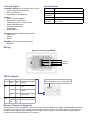
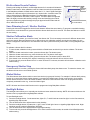
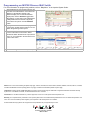
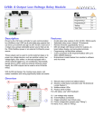
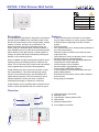
MVCA2: 2 Dial Dimmer Wall Switch
TM
Installation/Wiring:
??
Programming 1:
??
Programming 2:
??
Testing:
??
Total Time:
??
DRAFT
MVCA2
Description
Features
The 2 Dial Dimmer Wall Switch is designed to work with the
Imperial system’s MAMA home automation engine. Each
dial can be programmed to control a single output, multiple
outputs, or macros, and this in any combination. The
dimmer wall switch can provide adjustable control (32
dimming steps) of dimmable lights, motorized shutters, or
other adjustable devices. Set the dial to the desired position
without waiting for the light intensity or shutter position to
change, the system will adjust automatically including the
displays on all controlling devices.
•
Unique to MAMA, the light intensity/shutter position can be
saved by pushing and holding the dial on a dimmer wall
switch. The next time the dial is pushed it will automatically
set the lights/shutters to the saved intensity/position.
All wall switches are driven by the V32 controller’s 4 wire
low-voltage Multibus. This means that the high voltage
wiring is not connected directly to the Wall Switch as in
regular electrical systems. This also means they can be
installed anywhere including wet areas or outdoors
(avoiding direct sunlight, or exposure to rain/snow).
•
2 rotary dials with push on/off action to dim outputs,
such as lights or shutters or macros (group of outputs)
8 LEDs per dial to display light intensity or shutter
position
32 dimming steps
Save light intensity level or shutter position (push dial to
go to the saved position)
Unlimited number of switches can control the same
output (max 250)
Global buttons to control an alternate device or macro
Emergency stop for motorized shutters
Adjust LED light intensity with Day/Night adjustment
Copy/Paste for module duplication
Custom designer colours available
Remote firmware upgradeability via bus
Programming via BabyWare software
4 wire connection to the Imperial Multibus with up to
900m (3000ft) distance
Bi-directional Locate feature from module to software
and vice versa
Single gang box installation
1)
2)
3)
4)
5)
Output and macro control dials
Backlight button
Light intensity / shutter position LEDs
Global button
Multibus feedback LEDs
•
•
•
•
•
•
•
•
•
•
•
•
•
All wall switches can be duplicated with no limitation to the
number of dimer wall switches that can control an output.
Overview
3
1
4
2
5
A) 4-wire Multibus connection
A
Related Topics
Specifications
Installation / Wiring (refer to Imperial System Guide)
• System Diagrams and Wiring Tips
• Wire Gauge Selection
• Conventional vs. MAMA Wiring
Input voltage
Typically 12Vdc (from Multibus)
Multibus
4 wire at up to 900m (3,000ft)
Current
Consumption
80mA
Features
• Remote Firmware Upgrade
• Bi-directional Locate Feature
• Save Dimming Level / Shutter Position
• Shutter Calibration Mode
• Emergency Shutter Stop
• Global Button
• Backlight Button
Dimensions
7.4cm X 11cm X 2.5cm (2.9” X 4.3” X 1”)
Operating
Temperature
-10ºC to 50ºC
14ºF to 122ºF
Applications (refer to Imperial System Guide)
• Light Control
• Shutters
• Macros
BabyWare (refer to Imperial System Guide)
• BabyWare
Wiring
Figure 20: Connecting an MVCA2
Imperial
Multibus
LED Feedback
BUS
Red
on
Red
flash
RX
TX
STATUS
Green
flash
Green
flash
OK (communication in
progress)
-
-
Com fail: Short on GRN
or YEL
-
Green
on
Com fail: too many
modules
Green
on
Green
on
Com fail: GRN and YEL
lines reversed
-
-
Green
flash
Green
flash
Status Bar
LEDs indicate dimmer level / shutter position
Bus power too low
Module locate mode
Remote Firmware Upgrade
The MVCA2 is firmware upgradeable remotely via the V32 controller’s Multibus at 57.6Kbps. Using BabyWare connect to
the V32 account using any of the connection methods (direct connect, IP static, or IP DNS). Right-click the desired wall
switch and select Upgrade. A firmware upgrade for a single module or group of modules will take usually less than 10
minutes, which keeps system downtime to a minimum.
Bi-directional Locate Feature
Figure 21: Initiating a Locate
Pressing and holding the Global 1 and Backlight buttons for 3 seconds will initiate the
Module Locate feature. When a Module Locate is initiated, the switch’s representation
in the BabyWare software will flash and the status bar’s 2, 3, 4 and 5 lights flash (light
2 flashes at a different rate) to indicate that it is in locate mode. A module locate can
also be initiated from the BabyWare software. From BabyWare right-click the
module’s representation and select Locate Physical. The dial’s status bar lights will
flash. We highly recommend that after pressing locate and identifying the module,
open the programming page and assign the proper physical location label and the
doors’ labels and locations.
LEDs
will flash
Press and hold to initiate
the Locate feature
Save Dimming Level / Shutter Position
Pressing the dimmer dial toggles the device’s state between Off and the saved setting. To program a new default setting,
set the device to the desired level, press and hold the dimmer dial button for 2 seconds. The status bar flashes to confirm
the new setting.
Shutter Calibration Mode
In order to control a shutter, you must first “teach” the dimmer dial. This is necessary to account for different shutter sizes
and motor speeds. Because shutters come in different sizes, this calibration method can only be used when only one
shutter is assigned to a dimmer dial. This calibration can also be performed locally at the HV8D, or using BabyWare (Q2
2009).
To calibrate a dimmer dial for a shutter:
1) To enter shutter calibration mode, press and hold the Global button and the dial you wish to calibrate. The shutter
closes.
2) When the shutter reaches the bottom, press the dimmer dial. The shutter opens.
3) When the shutter reaches the top, press the dimmer dial. The shutter closes again.
4) When the shutter reaches the bottom, press the dimmer dial. The shutter opens to about 50%.
5) If the shutter is not at exactly 50%, adjust it manually by turning the dimmer dial one click at a time.
6) To save and exit, press the dimmer dial. If no action is taken for 4 minutes, the switch will exit shutter calibration mode
without saving.
Emergency Shutter Stop
If a window shutter is in motion, pressing the dimmer dial immediately stops the shutter motor. To restart the shutter, turn
the dimmer dial to select a new shutter position.
Global Button
The Global button allows dimmer dials to control two devices (or groups of devices). For example if a dimmer dial’s primary
function is to control the kitchen window shutters, by pressing the Global button, the dial could switch to its secondary
function which could be to control all window shutters in the house. Global function could even be programmed with a
completely unrelated function e.g. control the kitchen lights.
NOTE: All button and dimmer dial functions can be programmed using BabyWare software.
Backlight Button
The backlight button allows you to manually set the dimmer button status bar intensity. NOTE: All button and dimmer dial
functions can be programmed using BabyWare software.
To enter Backlight mode:
1) Press the backlight button. On the status bars, lights 5, 6, 7 and 8 illuminate as well as light 1 on the first status bar,
signalling Day Adjust mode.
2) Turn the left dimmer dial to adjust status bar day intensity.
3) Press the backlight button. On status bar 1, light 1 turns off and light 2 turns on signalling Night Adjust mode. Night
schedule must be enabled in BabyWare (Q2 2009).
4) Turn the left dimmer dial to adjust status bar light night intensity.
5) To save and exit, press the backlight button. If no action is taken for 60 seconds, the switch will exit Backlight mode
without saving.
Programming an MVCA2 Dimmer Wall Switch
For more information on programming modules, refer to “BabyWare ” in the Imperial System Guide.
1
When BabyWare is communicating with the V32
controller and a Wall Switch is connected to the
Multibus, it automatically appears in the
Switches display area. To view the Switches
display area, click the Switches toggle button.
Alternatively, you may wish to add a Wall Switch
to BabyWare before the module is physically
connected to the system. Click the Add Item
button.
2
To program a Wall Switch that already appears
in the system, double-click the switch’s icon. The
Switch Programming window opens.
4
Click Add Action under the Button # ON header
to set an ON action for each button. Select
whether the button will activate an output, start a
macro, or any combination. Do the same for the
button’s OFF action.
5
Click the Backlight Levels button (Q2 2009)
Patents: One or more of the following US patents may apply: 7046142, 6215399, 6111256, 6104319, 5920259, 5886632, 5721542, 5287111, 5119069,
5077549 and RE39406 and other pending patents may apply. Canadian and international patents may also apply.
Trademarks: Paradox Imperial, MAMA, BabyWare, the M logo, and the triangle logo are trademarks or registered trademarks of Paradox Security
Systems Ltd. or its affiliates in Canada, the United States and/or other countries.
Certification: For the latest information on products approvals, such as UL and CE, please visit www.paradox.com.
Warranty: For complete warranty information on this product please refer to the Limited Warranty Statement found on the website www.paradox.com/
terms. Your use of the Paradox product signifies your acceptance of all warranty terms and conditions.
© 2009 Paradox Security Systems Ltd. All rights reserved. Specifications may change without prior notice.
PARADOX.COM
Printed in Canada - 04/2009
IMVCA2-EI01