1
PS27D: 4-Output 2.85A Power Supply Module
TM
Installation/Wiring:
1 hr
Programming 1:
2 hr
Programming 2:
1 hr
Testing:
1 hr
Total Time:
5 hr
DRAFT
Description
Features
Driven by the V32 main controller’s 4-wire communication
bus (Multibus), the PS27D module is a fully-supervised
2.85A switching power supply with 4 auxiliary outputs that
provide 12Vdc, 500mA each. These outputs can be
connected in parallel to combine output power.
•
The PS27D provides features local output control buttons,
Multibus and power status LEDs, and a 7-segment display
that shows the voltage and amperage of each output, or
sum of all outputs. Using BabyWare, outputs can also be
configured to be used as PGMs.
•
•
•
•
•
•
•
•
•
•
2.85A built-in switching power supply with transformer
sharing (share central supply throughout the system)
4 auxiliary outputs providing 13.8Vdc, 500mA each (can
be used in parallel to increase output current)
Auxiliary outputs can be used as PGMs
7-segment display for voltage and amperage of each
output, or sum of all outputs
On-board buttons to manually turn on/off each output
Supervises AC, battery, low battery and output limit
Selectable battery charge current (350mA/500mA)
Connects to Multibus: 4-wire encrypted 13.8Vdc communication bus at 500bps
Remote firmware upgrade via Multibus using RS-485 at
57.6Kbps
All programming is done using BabyWare PC Software
DIN rail enclosure with removable terminals for fast,
secure, orderly and economic installation
Overview
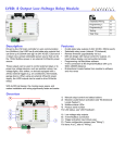
1) Local on/off control for each output with space to label
each output
2) Power status LEDs (page 3)
3) Press the LOC button to perform a module locate (see
“Bi-directional Locate Feature” on page 3)
4) Multibus status LEDs (see page 3)
5) 4-wire Multibus connection
A) Each output provides 13.8Vdc, 500mA (see “Combining
Output Power (Parallel)” on page 2)
B) Displays voltage and amperage supplied to the aux.
outputs (see “Volt / Amp Display” on page 3)
C) Power input: 16-24Vac / 16-36Vdc
D) Product serial number
E) Fuse not required (PS27D features fuseless protection)
F) Battery backup: 12Vdc, 7Ah
A
B
C
1
2
3
D
4
E
5
F
PS27D - page 1
Related Topics
Specifications
Installation / Wiring (see Imperial System Guide)
• DIN Rail Enclosure
• System Diagrams and Wiring Tips
• Wire Gauge Selection
Operating
Voltage
16-24Vac (50 or 60Hz), or
16-36Vdc
Power rating
50W / 75VA
Aux. Outputs
Typical 12Vdc (10.8 to 13.8Vdc), 500mA per
output with fuseless shutdown.
Features
• Remote Firmware Upgrade (see page 3)
• Bi-directional Locate Feature (see page 3)
Connect in parallel to combine output power:
For example, combine 1-4 for 1 output at 2A
For example, combine 1-2 for 1 output at 1A
Applications (see Imperial System Guide)
• Wall Switches
• Macros
Battery
12Vdc, 7Ah minimum
Multibus supply 13.8Vdc
BabyWare (see Imperial System Guide)
• BabyWare
Dimensions
Standard DIN9
Operating
Temperature
0ºC to 50ºC
32ºF to 122ºF)
Wiring
Refer to Figure 1 on page 2 for information wiring the PS27D.
Transformer Sharing
The PS27D features Transformer Sharing that enables modules with this feature to share a central transformer (16-24Vac,
or 16-36Vdc) throughout the system. Ensure that the total power output of the transformer is respected. There is no specific
polarity connection when using a DC transformer.
Combining Output Power (Parallel)
These outputs can be wired in parallel, to combine output power. For example, in Figure 1 outputs 2 and 3 were connected
in parallel to provide one output at 1A. Another example would be to wire all 4 outputs in parallel to provide one output at
2A. To wire in parallel:
1) Using the local control buttons, deactivate the outputs (LED off) you want to combine. If outputs are not first
deactivated, the correct voltage and amperage will not be displayed.
2) Wire the outputs you want to combine in parallel as shown in Figure 1.
3) Reactivate the combined outputs by pressing only one of the local control buttons. For example, in Figure 1 pressing
local control button 2 will reactivate outputs 2 and 3.
Figure 1: PS27D Wiring Diagram
see “Combining Output Power
(Parallel)” on page 2
16-24Vac, or
16-36Vdc
Transformer
1A
+ -
see “Transformer Sharing”
on page 2
~ ~
500mA
+
500mA
+
500mA per output
2A max
Outputs can be paralleled
16 / 24 Vac
16 / 24 Vac
ACM24D
Imperial Multibus
+
-
12Vdc
Battery
PS27D - page 2
Feedback Display
Multibus Status LEDs
R = Red G = Green B = Blue
= Off
= On
B
R
G
G
OK (com in
progress)
= Flashing
R
G
G
R
G
G
R
G
firmware upgrade Module locate
in progress
mode
Battery voltage
low
Com fail, or too
many modules
Bus reversed
(GRN/YEL)
R
BUS short
(GRN/YEL)
Power Status LEDs
R = Red G = Green B = Blue
= Off
= On
G
G
AC or DC power
is supplied
Battery is low /
charging
G
On for less than 4
sec. = battery test
Volt / Amp Display
Normal Mode
Not in Output or Global mode.
Output Mode
Press and hold an output button for two seconds.
Exits in 5 minutes or by pressing and holding the
same button.
Global Mode
Press and hold buttons 1 and 4 for two seconds.
Exits in 5 minutes or by pressing and holding
buttons 1 and 4.
VOLT
Voltage that can be
supplied to outputs
VOLT
Cycles between output #
(e.g. o-1) and voltage
being supplied to
selected output.
VOLT
Cycles through the
voltage of each output
followed by total of all
four outputs
AMP
Total amperage supplied
to all four outputs
AMP
Amperage supplied to
selected output
AMP
Cycles through the
amperage of each output
followed by total of all
four outputs
Bi-directional Locate Feature
Pressing and holding the LOC button for 3 seconds will initiate the Module Locate feature. When a Module Locate is
initiated, the module’s representation in the BabyWare software will flash and the module’s BUS, RX and TX LEDs will flash
to indicate that it is in locate mode. A module locate can also be initiated from the BabyWare software. From BabyWare
right-click the module’s representation and select Locate Physical. The module’s BUS, RX and TX LEDs will flash. We
highly recommend that after pressing locate and identifying the module, open the programming page and assign the proper
physical location label and the doors’ labels and locations. After complete connection, use the space provided on the
module to indicate the doors’ description.
Remote Firmware Upgrade
Work in progress...The PS27D is firmware upgradeable remotely via the V32 controller’s Multibus at 57.6Kbps. Using
BabyWare connect to the V32 account using any of the connection methods (direct connect, IP static, or IP DNS). Rightclick the desired module and select Upgrade (???). A firmware upgrade for a single module or group of modules will take
usually less than 10 minutes, which keeps system downtime to a minimum.
PS27D - page 3
Programming a PS27D Module
Figure 2: PS27D Programming
1) When BabyWare is communicating with the V32 controller and a PS27D
module is connected to the Multibus, it automatically appears in the Mama
Modules display area. To view the Mama Modules display area, click the
Modules toggle button. Alternatively, you may wish to add a module to
BabyWare before the module is physically connected to the system. Click the
Add Item button. Refer to Figure 2.
2) To program a module that already appeared in the system, double-click the
module’s icon. The PS27D Programming window opens.
3) From the PS27D Programming window, you can set the battery charging
current and the AC failure/restore delay. Click OK.
Related Topics
• If you have trouble locating the module in BabyWare, you can use the Module
Locate Feature (see “Bi-directional Locate Feature” on page 3)
Patents: One or more of the following US patents may apply: 7046142, 6215399, 6111256, 6104319, 5920259, 5886632, 5721542, 5287111, 5119069,
5077549 and RE39406 and other pending patents may apply. Canadian and international patents may also apply.
Trademarks: Paradox Imperial, MAMA, BabyWare, the M logo, and the triangle logo are trademarks or registered trademarks of Paradox Security
Systems Ltd. or its affiliates in Canada, the United States and/or other countries.
Certification: For the latest information on products approvals, such as UL and CE, please visit www.paradox.com.
Warranty: For complete warranty information on this product please refer to the Limited Warranty Statement found on the website www.paradox.com/
terms. Your use of the Paradox product signifies your acceptance of all warranty terms and conditions.
© 2009 Paradox Security Systems Ltd. All rights reserved. Specifications may change without prior notice.
PARADOX.COM
Printed in Canada - 03/2009
IPS27-EI00
PS27D - page 4