1
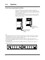
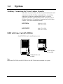
Digital Super Hybrid System
KX-TD816CE
KX-TD1232CE
Added and Changed Features for
Installation Manual and Programming Tables
Vol. 2
Please read this manual first and then the Installation Manual.
In this manual, the last letter “CE” of each model number is omitted.
Table of Contents
Additions to KX-TD816/1232
Section 1.4, Options
16 SLT Line Circuit Unit (KX-TD174)...............................................................................6
Auxiliary Connection for Power Failure Transfer...............................................................7
ISDN 6-S0 Line Unit (KX-TD286).....................................................................................7
Section 2.4, Optional Cards and Units Installation
16 SLT Circuit Line Connection .........................................................................................8
Installing Expansion Unit (KX-TD174)..............................................................................8
Cable Pin Numbers to Be Connected ..................................................................................9
ISDN 6-S0 Line Unit Connection ......................................................................................10
Installing Expansion Unit (KX-TD286)..............................................................................11
Internal ISDN S0 Line Connection .....................................................................................12
Section 3, Features
ISDN Extension ..................................................................................................................14
Section 4, System Programming
[012] ISDN Extension Number Set ....................................................................................16
[013] ISDN Extension Name Set .......................................................................................18
[014] Budget Management on ISDN Port..........................................................................19
[424] ISDN Port Type ........................................................................................................20
[425] ISDN Layer 1 Active Mode......................................................................................21
[426] ISDN Configuration..................................................................................................22
[427] ISDN Data Line Mode..............................................................................................23
[428] ISDN TEI Mode .......................................................................................................24
[429] ISDN Extension Multiple Subscriber Number .........................................................25
[430] ISDN Extension Progress Tone ................................................................................26
[612] Incoming Call Display..............................................................................................27
[613] ISDN Class of Service ..............................................................................................28
[614-615] Outgoing Permitted CO Line Assignment– Day/Night for ISDN Extension ...29
[990] System Additional Information, Fields (28) through (38)........................................31
Changes
Section 3, Features
Budget Management............................................................................................................34
CO Incoming Call Information Display.............................................................................34, 38
Display, Call Information ....................................................................................................34
Module Expansion...............................................................................................................34
Station Message Detail Recording (SMDR) .......................................................................34
Section 4, System Programming
[001] System Speed Dialing Number Set...........................................................................34
[105] Account Codes ..........................................................................................................35
[109] Expansion Unit Type ................................................................................................35
[125] User Password ..........................................................................................................36
[417] CO Line Name Assignment......................................................................................36
[418] ISDN Line Number Assignment ..............................................................................36
[419] ISDN Outgoing CLIR Service Assignment..............................................................36
2
Table of Contents
[420]
[601]
[611]
[991]
ISDN DDI Service Assignment................................................................................36
Class of Service.........................................................................................................37
ISDN DDI Number / Floating Number Transformation...........................................37
COS Additional Information.....................................................................................37
Programming Tables for Added and Changed Features
[012]
[013]
[014]
[105]
[109]
[418]
[419]
[420]
[424]
[425]
[426]
[427]
[428]
[429]
[430]
[611]
[612]
[613]
[614]
[615]
[990]
ISDN Extension Number Set ....................................................................................42
ISDN Extension Name Set .......................................................................................42
Budget Management on ISDN Port..........................................................................42
Account Codes ..........................................................................................................43
Expansion Unit Type ................................................................................................45
ISDN Line Number Assignment ..............................................................................46
ISDN Outgoing CLIR Service Assignment..............................................................46
ISDN DDI Service Assignment................................................................................46
ISDN Port Type ........................................................................................................47
ISDN Layer 1 Active Mode......................................................................................47
ISDN Configuration..................................................................................................47
ISDN Data Line Mode..............................................................................................47
ISDN TEI Mode .......................................................................................................48
ISDN Extension Multiple Subscriber Number .........................................................48
ISDN Extension Progress Tone ................................................................................48
ISDN DDI Number / Floating Number Transformation...........................................48
Incoming Call Display..............................................................................................49
ISDN Class of Service ..............................................................................................49
Outgoing Permitted CO Line Assignment– Day for ISDN Extension .....................50
Outgoing Permitted CO Line Assignment– Night for ISDN Extension...................51
System Additional Information ................................................................................52
3
Additions to KX-TD816/1232
1.4
Options
16 SLT Line Circuit Unit (KX-TD174)
Each unit adds eight extensions which contain two single line
telephones. The unit can support 16 single line telephones per unit.
One unit for the KX-TD816 and up to two units for the KX-TD1232
can be installed per system.
Each single line telephone in the same jack has different extension
number so that it can act as completely different extension like an
eXtra Device Port feature.
D816
D1232
DIGITAL SUPER HYBRID SYSTEM
DIGITAL SUPER HYBRID SYSTEM
Panasonic
16 single line
telephones can be
added.
Panasonic
16 or 32 single line
telephones can be
added.
Note:
• Installing this unit allows the eXtra Device Port setting to “Enable” automatically in system
programming [600]. However, assigning “Disable” makes a single line telephone which is
connected to the second jack (Jack xx-2) disable to use.
• This unit cannot support the proprietary telephone and Voice Mail Integration features.
• This unit has four DTMF receivers; two receivers in the first eight ports and two receivers in
the last eight ports.
• The Ringing Patterns for all single line telephones which are connected to the system are
changed as below;
Incoming call from outside line
1S
6
Incoming call from extension
1S
1.4
Options
Auxiliary Connection for Power Failure Transfer
When there is a power failure, the first two jacks on this unit can be
connected to specific CO lines mentioned below. An auxiliary
connection is required to implement this feature. For more
information about the connection between an extension jack to a
CO line, refer to the “2.5 Auxiliary Connection for Power Failure
Transfer” in the main Installation Manual.
KX-TD816
Jack 09-1...CO 5
Jack 10-1...CO 6
KX-TD1232
Jack 17-1...CO 9
Jack 18-1...CO10
ISDN 6-S0 Line Unit (KX-TD286)
One KX-TD286 can be installed per system.
D816
D1232
DIGITAL SUPER HYBRID SYSTEM
DIGITAL SUPER HYBRID SYSTEM
Panasonic
6 ISDN S0 lines
can be added.
Panasonic
6 ISDN S0 lines can
be added.
Note
Either one KX-TD280, one KX-TD286 or one KX-TD180 can be installed in a system.
7
2.4
Installation of Optional Cards and Units
16 SLT Circuit Line Connection
Installing one unit to the system allows 16 single line telephones
(SLT’s) to be connected to jacks 09 through 16 for the KX-TD816,
or jacks 17 through 24 or jacks 25 through 32 for the KX-TD1232.
Installing two units allows 32 SLT’s to be connected to jacks 17
through 32 for the KX-TD1232.
This unit can be installed to any of the expansion areas provided on
the front of the system.
For unit installation, refer to the procedure “Section 2.4.4
“Installing Expansion Unit (KX-TD170/KX-TD180)” in the main
Installation Manual. Steps 1 through 5 and 7 through 10 of the
installation procedure are the same as the other expansion units.
Step 6 is different for each unit. Please note the following
instructions below instead of step 6 (Installation Manual) for this
unit.
Note
• System Programming [109] Expansion Unit Type is required for the
expansion unit location identification.
Installing Expansion Unit (KX-TD174)
Step 6
■
If the KX-TD174 is installed, use an Amphenol Connector to connect extensions.
Insert the connector into the jack.
To 4-CO Line Unit KX-TD180
(Jack for Power Failure Transfer†)
P
FT
po
rt
s
Connector type
50-pin (Amphenol 57JE
series or the equivalent)
25
1
50
26
P
an
as
on
ic
To extensions
KX-TD816 : Jacks 09 - 16
KX-TD1232 : Jacks 17 - 24 or 25 - 32
8
Installing Expansion Unit (KX-TD174)
Note:
• To fix the connector, refer to “Section 2.4.4 “Installing Expansion Unit (KX-TD170/KX-TD180),
Amphenol 57 Type (screw-attach-type 50-pin connector) Connection for KX-TD170” in the main
Installation Manual.
• For jack connection, please see “Cable Pin Numbers to Be Connected” on the next page.
• †For more information, see “Auxiliary Connection for Power Failure Transfer” in this leaflet.
• The KX-TD1232 is illustrated above.
Cable Pin Numbers to Be Connected
Clip
CONN. Terminal
PIN
(KX-A205)
No.
26
1
27
2
1
2
3
4
28
3
29
4
5
6
7
8
30
5
31
6
9
10
11
12
32
7
33
8
13
14
15
16
34
9
35
10
17
18
19
20
36
11
37
12
21
22
23
24
38
13
39
14
25
26
27
28
40
15
41
16
29
30
31
32
For KX-TD816
For KX-TD1232
(Expansion 1)
For KX-TD1232
(Expansion 2)
Jack No. 9-16
Jack No.17-24
Jack No. 25-32
Jack. 09 - 1
Jack. 10 - 1
Jack. 11 - 1
Jack. 12 - 1
Jack. 13 - 1
Jack. 14 - 1
Jack. 15 - 1
Jack. 16 - 1
Jack. 09 - 2
Jack. 10 - 2
Jack. 11 - 2
Jack. 12 - 2
Jack. 13 - 2
Jack. 14 - 2
Jack. 15 - 2
Jack. 16 - 2
T
R
T
R
T
R
T
R
T
R
T
R
T
R
T
R
T
R
T
R
T
R
T
R
T
R
T
R
T
R
T
R
Jack. 17 - 1
Jack. 18 - 1
Jack. 19 - 1
Jack. 20 - 1
Jack. 21 - 1
Jack. 22 - 1
Jack. 23 - 1
Jack. 24 - 1
Jack. 17 - 2
Jack. 18 - 2
Jack. 19 - 2
Jack. 20 - 2
Jack. 21 - 2
Jack. 22 - 2
Jack. 23 - 2
Jack. 24 - 2
T
R
T
R
T
R
T
R
T
R
T
R
T
R
T
R
T
R
T
R
T
R
T
R
T
R
T
R
T
R
T
R
Jack. 25 - 1
Jack. 26 - 1
Jack. 27 - 1
Jack. 28 - 1
Jack. 29 - 1
Jack. 30 - 1
Jack. 31 - 1
Jack. 32 - 1
Jack. 25 - 2
Jack. 26 - 2
Jack. 27 - 2
Jack. 28 - 2
Jack. 29 - 2
Jack. 30 - 2
Jack. 31 - 2
Jack. 32 - 2
T
R
T
R
T
R
T
R
T
R
T
R
T
R
T
R
T
R
T
R
T
R
T
R
T
R
T
R
T
R
T
R
9
Installing Expansion Unit (KX-TD286)
ISDN 6-S0 Line Unit Connection
To add six ISDN S0 lines, use the optional ISDN 6-S0 Line Unit
(KX-TD286). This unit can be installed in any of the expansion
areas provided on the front of the main unit.
When the KX-TD286 is installed in the KX-TD816, only four
ISDN S0 lines are available for outside lines and the other ports are
for extension lines (ISDN extensions).
System programming is required for unit location identification.
Default KX-TD816: bottom = 4-CO Line Unit,
top = 8-Station Line Unit
KX-TD1232: bottom = 4-CO Line Unit,
middle and top = 8-Station Line Unit
10
Installing Expansion Unit (KX-TD286)
For unit installation, refer to the procedure “Installing Expansion
Unit (KX-TD280)” in the main Added and Changed Features for
Installation Manual and Programming Tables. Steps 1 through 5
and 8 through 11 of the installation procedure are the same as the
KX-TD280. Step 6 and Step 7 are different from those of KXTD280. Please note the following instructions below instead of
step 6 and step 7 for this unit.
Note
• System Programming [109] Expansion Unit Type is required for the
expansion unit location identification.
6. Prepare the required plugs. Six 4-pin
plugs are included in KX-TD286 to
connect CO lines or ISDN terminal
equipment.
7. Insert the plug into a jack on the unit.
Connect an earth wire to the earth terminal
on the extension expansion unit.
KX-TD286
Jack
no.
S01
S02
S03
S04
S05
TB
TA
RA
RB
RB
RA
TA
TB
for internal
ISDN S0
line
S06
P
an
as
on
ic
To Terminal Board or Modular
Jacks from the Central Office
Note
• All ports can be either for CO line or
extension line.
11
Internal ISDN S0 Line Connection
The ISDN S0 Bus on the KX-TD280 and the KX-TD286 can be
used as internal S0 bus. Each port can be used as either external or
internal ISDN S0 Lines. Some System Programs are required to
use the S0 bus as internal ISDN S0 lines beforehand.
Connection
Use 4-pin plugs (included) to connect ISDN S0 lines. A single plug
is able to connect one ISDN S0 line. Mis-connection may cause the
system to operate improperly.
1. Re-arrange telephone wires in reverse order of the plug.
2. Insert the plug into a ISDN S0 port on the unit.
Wiring for external ISDN S0 line
Wiring for internal ISDN S0 line
TB
RB
TA
RA
RA
TA
RB
TB
KX-TD280
KX-TD286
P
FT
TB
TA
RB
RA
RA
RB
TA
TB
Jack
no.
S01
po
rts
2C
O
w
/P
FT
2C
O
ISDN
Port No.1
S02
S03
For internal
ISDN S0 line
S04
S05
P
an
as
P
on
ic
Notes
an
ISDN
Port No.2
as
on
ic
TB
TA
RA
RB
RB
RA
TA
TB
For
internal
ISDN S0
line
S06
For installing the KX-TD280 or KX-TD286 to main unit, refer to
“Installing Expansion Unit” respectably.
3. Connect the lines between the ISDN board and the ISDN device.
4. Plug the AC power cord into the system and an AC outlet.
5. Program “[424] ISDN Port Type” and other required programs
in System Programming.
6. Press the Reset Button with a pointed tool on the main unit.
12
Internal ISDN S0 Line Connection
Maximum cabling distance of S0 bus connection
The maximum length of the extension line cord that connects the
main unit and the ISDN terminal equipment (TE) is shown below:
Under 1000 m
D1232
DIGITAL SUPER
HYBRID SYSTEM
Point-to-Point
TE
Panason
ic
Point-to-Multipoint
TE 1
TE 8
Under 150 m
Expansion Point-to-Multipoint
TE 1
Under 500 m
TE 8
Under 50 m
Wiring with Terminating Resistors (TR)
The ISDN S0 bus should be terminated with two100Ω terminating
resistors (TR).
TR†
Main
Unit
TE 1
TE 8
†TR
RB
RA
TA
TB
TR 100Ω
TR 100Ω
Power Supply for ISDN Terminal Equipment (TE)
The system does not provide a power supply to terminal equipment
(TE). Depending on the type of TE's, the external power supply is
required on ISDN S0 line to operate.
13
I
3
Features
ISDN Extension
Description
The system supports terminal equipments with separate power
supplies. For example, ISDN telephone, G4 Facsimile and
personal computers which are connected to optional ISDN S0 Line
Unit : KX-TD280 or KX-TD286. A maximum of eight terminal
equipments can be connected to each ISDN S0 bus with point-tomulti-point configuration. Terminal equipments can be addressed
individually with Multiple Subscriber Numbers (MSN). The MSN
consists of the ISDN extension number and an additional digit, 0
through 9. If MSN is not assigned, all equipments on the same S0
bus are called simultaneously.
The following bearer capabilities can be supported:
Transfer Capability
Transfer Mode
Circuit
Unrestricted digital
Circuit
Speech
Circuit
3.1 kHz Audio
The functions of terminal equipment are similar to single line
telephone functions, but the following features are not available.
• Automatic Callback Busy
• Conference
• Call Forwarding
• Do Not Disturb
• Call Hold
• Log-In / Log-Out
• Call Park
• Message Waiting
• Call Pickup
• Paging – Group Answer
• Call Transfer
• Pickup Dialing
• Call Waiting
• Timed Reminder
Conditions
• Class of Service for ISDN extension port applies to all terminal
equipments on the same S0 bus.
• Each port can be assigned as follows:
*1 and *2: can be either an external or internal ISDN S0 line.
*1: when assigned as internal, the corresponding analog CO ports
become available.
TD1232
TD816
CO
No.
1, 2
14
ISDN TD280 TD286
Port
—
*1
1
CO
No.
1, 2
ISDN TD280 TD286
Port
—
*1
1
3, 4
2
—
*1
3, 4
2
—
*1
5, 6
3
*2
*2
5, 6
3
—
*1
7, 8
4
*2
*2
7, 8
4
—
*1
—
5
—
Internal
9, 10
5
*2
*2
—
6
—
Internal
11, 12
6
*2
*2
3
I
Features
Connection References
In this manual
Section 2, Installation
Internal ISDN S0 Line Connection
Programming References
In this manual
Section 4, System Programming,
[012] ISDN Extension Number Set
[013] ISDN Extension Name Set
[014] Budget Management on ISDN Port
[109] Expansion Unit Type
[424] ISDN Port Type
[425] ISDN Layer 1 Active Mode
[426] ISDN Configuration
[427] ISDN Data Link Mode
[428] ISDN TEI Mode
[429] ISDN Extension Multiple Subscriber Number
[430] ISDN Extension Progress Tone
[613] ISDN Class of Service
[614-615] Outgoing Permitted CO Line Assignment – Day/Night for
ISDN Extension
• The possible parameter combinations are listed below. The underlined
selections are recommended. The selections marked "*" are activated,
regardless of the assignments.
Program
[424] ISDN [425] ISDN [426] ISDN [427] ISDN
Port Type Layer 1 Active Configuration Data Link
Mode
Mode
Permanent
Fix 0-63
Automatic
(not available)
—
—
Call/
Permanent
P–P
Call/
Permanent
Fix 0-63*
Call/
Permanent
P–M
Call*
Automatic*
Permanent
P–P
—
CO
Parameter
Extension
Feature References
None
Operation References
None
[428] ISDN
TEI Mode
P–M
15
012
4.2
Manager Programming
ISDN Extension Number Set
Description
Assigns an extension number to each port which is connected to the
ISDN S0 unit or card.
Selection
• Port number: KX-TD816—01 through 06
KX-TD1232—01 through 12
• Extension Number: 2 or 3 digits
Default
All ports – Not stored
Programming
1.
Enter 012.
Display: ISDN EXT NO.
2.
Press NEXT.
Display: Port NO?–>
3.
Enter a port number.
To enter a first port number, you can also press NEXT.
Display: #01:Not Stored
4.
Enter an extension number.
To change the current entry, press CLEAR and the new number.
Conditions
16
5.
Press STORE.
6.
To program another port, press NEXT or PREV, or SELECT
and the desired port number.
7.
Repeat steps 4 through 6.
8.
Press END.
• Each extension number can be two or three digits, consisting of 0
through 9. The and # keys cannot be used.
• A multiple subscriber number (MSN) is determined regarding this
assignment. The MSN consists of the assigned extension number and an
additional digit, 0 through 9.
Example) In case that the ISDN extension number is assigned “3”;
30 through 39 are effective as MSN's. The extension user can call any
terminal equipment on the ISDN S0 bus with MSN individually.
Pressing “30” calls all extensions on the ISDN S0 bus simultaneously.
• Port numbers 01 through 06 are for the Master System and 07 through
12 are for the Slave, if available.
4.2
Manager Programming
012
ISDN Extension Number Set (contd.)
• An extension number is invalid if the leading first or second digits
disagree with the setting of the program [100] “Flexible Numbering, 1st
through 16th hundred extension blocks.” If one digit is assigned as the
leading digit, some extensions have two digits and some have three
digits. If two digits are assigned, some have three digits and some have
four digits.
• Double entry or incompatible entry is invalid including the assignment
of program [813] “Floating Number Assignment.” Valid entry
examples: 10 and 11; 10 and 110. Invalid entry examples: 10 and 106;
210 and 21.
• Program [013] “ISDN Extension Name Set” is used to give names to
the extension numbers.
Feature References
None
17
013
4.2
Manager Programming
ISDN Extension Name Set
Description
Assigns names to the ISDN extension numbers programmed in
program [012] “ISDN Extension Number Set.”
Selection
• Port number: KX-TD816—01 through 06
KX-TD1232—01 through 12
• Name: 10 characters (max.)
Default
All ports – Not stored
Programming
1.
Enter 013.
Display: ISDN EXT. Name.
2.
Press NEXT.
Display: Port NO?–>
3.
Enter a port number.
To enter a first port number, you can also press NEXT.
Display: #01:Not Stored
4.
Enter a name.
For entering characters, see Section 4.1.3 “Entering Characters.”
To delete the current entry, press CLEAR.
To change the current entry, press CLEAR and the new name.
5.
Press STORE.
6.
To program another port, press NEXT or PREV, or
SELECT and the desired port number.
7.
Repeat steps 4 through 6.
8.
Press END.
Conditions
• Port numbers 01 through 06 are for the Master System and 07 through
12 are for the Slave, if available.
Feature References
None
18
4.2
Manager Programming
014
Budget Management on ISDN Port
Description
Assigns the charge limitation of a call on the ISDN extension port
basis.
Selection
• Port number: KX-TD816—01 through 06,
KX-TD1232—01 through 12,
( =all ports)
• Charge limitation (Charge): 0 through 59999
Default
All ports – 0
Programming
1.
Enter 014.
Display: ISDN Charge Lim.
2.
Press NEXT.
Display: Port NO?–>
3.
Enter a port number.
To enter a first port number, you can also press NEXT.
Display example: #01:
4.
0
Enter a charge limitation.
To delete the charge limitation, press CLEAR.
5.
Press STORE.
6.
To program another port, press NEXT or PREV, or
SELECT and the desired port number.
7.
Repeat steps 4 through 6.
8.
Press END.
Conditions
• If the charge limitation is set “0,” no restriction is applied.
• To assign all port to one selection, press the key at step 3.
In this case, the display shows the contents programmed for a first port.
• Port numbers 01 through 06 are for the Master System and 07 through
12 are for the Slave, if available.
• The displayed currency denomination can be programmed by [121]
Assignment of Denomination.
Feature References
Section 3, Features,
Budget management
Charge Fee Reference
19
4.6
424
CO Line Programming
ISDN Port Type
Description
Assigns the type of each port either CO line or extension line on
ISDN port basis.
Selection
• Port number: KX-TD816—01 through 04, ( =all ports)
KX-TD1232—01 through 12, ( =all ports)
• CO (CO line) / Extension
Default
All ports – CO
Programming
1.
Enter 424.
Display: ISDN Line Type
2.
Press NEXT.
Display: Port NO?–>
3.
Enter a port number.
To enter a first port number, you can also press NEXT.
Display example: #01:CO
4.
Keep pressing SELECT until the desired selection is
displayed.
5.
Press STORE.
6.
To program another port, press NEXT or PREV, or
SELECT and the desired port number.
7.
Repeat steps 4 through 6.
8.
Press END.
Conditions
• For the KX-TD816, port numbers 05 and 06 are fixed as “Extension.”
• For the KX-TD1232, port numbers 01 through 06 are for the Master
System and 07 through 12 are for the Slave, if available.
• To assign all ports to one selection, press the key at step 3. In this
case, the display shows the contents programmed for a first port.
• After this assignment, you should reset the system so that this
assignment is effective.
Feature References
None
20
4.6
CO Line Programming
425
ISDN Layer 1 Active Mode
Description
Assigns the active mode of Layer 1 on ISDN port basis.
Selection
• Port number: KX-TD816—01 through 06, ( =all ports)
KX-TD1232—01 through 12, ( =all ports)
• Permanent / Call
Default
• KX-TD816 Port 05 and 06– Call; other ports–permanent
• KX-TD1232 All ports – Permanent
Programming
1.
Enter 425.
Display: L1 Active Mode
2.
Press NEXT.
Display: Port NO?–>
3.
Enter a port number.
To enter a first port, you can also press NEXT.
Display example: #01:Permanent
4.
Keep pressing SELECT until the desired selection is
displayed.
5.
Press STORE.
6.
To program another port, press NEXT or PREV, or
SELECT and the desired port number.
7.
Repeat steps 4 through 6.
8.
Press END.
Conditions
• For the KX-TD1232, port numbers 01 through 06 are for the Master
System and 07 through 12 are for the Slave, if available.
• To assign all ports to one selection, press the key at step 3. In this
case, the display shows the contents programmed for a first port.
• After this assignment, you should reset the system so that this
assignment is effective.
Feature References
None
21
4.6
426
CO Line Programming
ISDN Configuration
Description
Assigns the configuration on ISDN port basis. This program is
available for ISDN extension only.
Selection
• Port number: KX-TD816—01 through 06, ( =all ports)
KX-TD1232—01 through 12, ( =all ports)
• Point (point to point) / Multipoint (point to multipoint)
Default
• KX-TD816 Port 05 and 06– Multipoint; other ports–Point
• KX-TD1232 All ports – Point
Programming
1.
Enter 426.
Display: Access Mode
2.
Press NEXT.
Display: Port NO?–>
3.
Enter a port number.
To enter a first port number, you can also press NEXT.
Display example: #01:Point
4.
Keep pressing SELECT until the desired selection is
displayed.
5.
Press STORE.
6.
To program another port, press NEXT or PREV, or
SELECT and the desired port number.
7.
Repeat steps 4 through 6.
8.
Press END.
Conditions
• For the KX-TD1232, port numbers 01 through 06 are for the Master
System and 07 through 12 are for the Slave, if available.
• If one equipment is connected to the ISDN port, select "Point." If
multiple equipments are connected, select "Multipoint."
• To assign all ports to one selection, press the key at step 3. In this
case, the display shows the contents programmed for a first port.
• After this assignment, you should reset the system so that this
assignment is effective.
Feature References
None
22
4.6
CO Line Programming
427
ISDN Data Link Mode
Description
Assigns the data link mode on ISDN port basis.
Selection
• Port number: KX-TD816—01 through 06, ( =all ports)
KX-TD1232—01 through 12, ( =all ports)
• Permanent / Call
Default
• KX-TD816 Port 05 and 06– Call; other ports–Permanent
• KX-TD1232 All ports – Permanent
Programming
1.
Enter 427.
Display: Data Link Mode
2.
Press NEXT.
Display: Port NO?–>
3.
Enter a port number.
To enter a first port number, you can also press NEXT.
Display example: #01:Permanent
4.
Keep pressing SELECT until the desired selection is
displayed.
5.
Press STORE.
6.
To program another port, press NEXT or PREV, or
SELECT and the desired port number.
7.
Repeat steps 4 through 6.
8.
Press END.
Conditions
• For the KX-TD1232, port numbers 01 through 06 are for the Master
System and 07 through 12 are for the Slave, if available.
• To assign all ports to one selection, press the key at step 3. In this
case, the display shows the contents programmed for a first port.
• After this assignment, you should reset the system so that this
assignment is effective.
Feature References
None
23
4.6
428
CO Line Programming
ISDN TEI Mode
Description
Assigns the Terminal Endpoint Identifier (TEI) mode on ISDN port
basis.
Selection
• Port number: KX-TD816—01 through 06, ( =all ports)
KX-TD1232—01 through 12, ( =all ports)
• Fix 0 through 63 / Automatic
Default
• KX-TD816 Port 05 and 06– Automatic; other ports–Fix 0
• KX-TD1232 All ports – Fix 0
Programming
1.
Enter 428.
Display: TEI Assign
2.
Press NEXT.
Display: Port NO?–>
3.
Enter a port number.
To enter a Port 01, you can also press NEXT.
Display example: #01:Fix 0
4.
Enter the TEI.
To change the current entry, press CLEAR and the new number.
If you do not enter a number, it is automatically assigned as
“Automatic.”
5.
Press STORE.
6.
To program another port, press NEXT or PREV, or
SELECT and the desired port number.
7.
Repeat steps 4 through 6.
8.
Press END.
Conditions
• For the KX-TD1232, port numbers 01 through 06 are for the Master
System and 07 through 12 are for the Slave, if available.
• If the "Point" is selected in program [426], assign the fixed TEI. If
"Multipoint" is selected, assign "Automatic."
• To assign all ports to one selection, press the key at step 3. In this
case, the display shows the contents programmed for Port 01.
• After this assignment, you should reset the system so that this
assignment is effective.
Feature References
None
24
4.6
CO Line Programming
429
ISDN Extension Multiple Subscriber Number
Description
Selects whether the Multiple Subscriber Number is allocated to
each terminal equipment on ISDN S0 bus or not on ISDN port
basis.
Selection
• Port number: KX-TD816—01 through 06, ( =all ports)
KX-TD1232—01 through 12, ( =all ports)
• Enable / Disable (no number)
Default
All ports – Disable
Programming
1.
Enter 429.
Display: MSN Service
2.
Press NEXT.
Display: Port NO?–>
3.
Enter a port number.
To enter a first port number, you can also press NEXT.
Display example: #01:Disable
4.
Keep pressing SELECT until the desired selection is
displayed.
5.
Press STORE.
6.
To program another port, press NEXT or PREV, or
SELECT and the desired port number.
7.
Repeat steps 4 through 6.
8.
Press END.
Conditions
• For the KX-TD1232, port numbers 01 through 06 are for the Master
System and 07 through 12 are for the Slave, if available.
• To assign all ports to one selection, press the key at step 3. In this
case, the display shows the contents programmed for a first port.
• You must assign the extension number to an ISDN terminal beforehand.
For details, refer to your terminal’s manual.
Feature References
None
25
4.6
430
CO Line Programming
ISDN Extension Progress Tone
Description
Enables or disables to send the progress tone to ISDN extension on
ISDN port basis.
Selection
• Port number: KX-TD816—01 through 06, ( =all ports)
KX-TD1232—01 through 12, ( =all ports)
• Enable / Disable (no tone)
Default
All ports – Disable
Programming
1.
Enter 430.
Display: ISDN EXT Tone
2.
Press NEXT.
Display: Port NO?–>
3.
Enter a port number.
To enter a first port number, you can also press NEXT.
Display example: #01:Disable
4.
Keep pressing SELECT until the desired selection is
displayed.
5.
Press STORE.
6.
To program another port, press NEXT or PREV, or
SELECT and the desired port number.
7.
Repeat steps 4 through 6.
8.
Press END.
Conditions
• For the KX-TD1232, port numbers 01 through 06 are for the Master
System and 07 through 12 are for the Slave, if available.
• To assign all ports to one selection, press the key at step 3. In this
case, the display shows the contents programmed for a first port.
Feature References
None
26
4.8
Extension Programming
612
Incoming Call Display
Description
Allows you to select between three display types when an incoming
call is received.
“Calling” means the incoming caller's telephone number is
displayed. “Called” means the called telephone number is
displayed. “Line Name” means the CO line name assigned in the
[417] program is displayed.
Selection
• Jack number: KX-TD816 – 01 through 16, ( =all jacks)
KX-TD1232 – 01 through 64, ( =all jacks)
• Display Types: Calling/ Called/ CO Line Name
Default
All jacks – Calling
Programming
1.
Enter 612
Display: Incoming Display
2.
Press NEXT.
Display: Jack NO?–>
3.
Enter a jack number.
To enter jack number 01, you can also press NEXT.
Display example: #01:Calling
Conditions
Feature References
4.
Keep pressing SELECT until the desired selection is
displayed.
5.
Press STORE.
6.
To program another jack, press NEXT or PREV, or
SELECT and the desired jack number.
7.
Repeat steps 3 through 6.
8.
Press END.
• In the case of the KX-TD1232, jack numbers 01 through 32 are for
the Master System and 33 through 64 are for the Slave, if available.
In this manual
Section 3, Features,
CO Incoming Call Information Display
Display, Call Information
27
613
4.8
Extension Programming
ISDN Class of Service
Description
Programs a Class of Service (COS) number for each ISDN
extension port. The COS determines the call handling abilities of
each port.
A primary and a secondary COS numbers can be assigned per port.
Selection
• Port number: KX-TD816—01 through 06, ( =all ports)
KX-TD1232—01 through 12,
( =all ports)
• COS number: 1 through 8
Default
All ports: Primary, Secondary – COS 1, COS 1
Programming
1.
Enter 613.
Display: ISDN COS Assign
2.
Press NEXT.
Display: Port NO?–>
3.
Enter a port number.
To enter a first number, you can also press NEXT.
Display example: #01:COS1,COS1
4.
Enter a COS number for primary number.
To change the current entry, enter the new number.
5.
Press
.
6.
Enter a COS number for secondary number.
To change the current entry, enter the new number.
7.
Press STORE.
8.
To program another port, press NEXT or PREV, or
SELECT and the desired port number.
9.
Repeat steps 4 through 8.
10.
Press END.
Conditions
• There is a maximum of eight Classes of Services. Every ISDN
extension must be assigned to a Class of Service and is subject to the
COS Programming of programs [500] through [508] and [991].
The restriction of program [991], field 1, applies only for analog
outside lines.
• Port numbers 01 through 06 are for the Master System and 07 through
12 are for the Slave, if available.
• To assign all ports to one selection, press the key at step 3. In this
case, the display shows the contents programmed for a first port.
Feature References
Section 3, Features,
Class of Service (COS)
28
4.8
Extension Programming
614-615
Outgoing Permitted CO Line Assignment – Day/Night for ISDN Extension
Description
Determines the CO lines which can be accessed by an ISDN
extension in both day and night modes. The extension users can
make outgoing outside calls using the assigned CO lines.
Selection
• Port number: KX-TD816—01 through 06,
( =all ports)
KX-TD1232—01 through 12, ( =all ports)
• CO line number: KX-TD816 – 01 through 08,
( =all CO lines)
KX-TD1232 – 01 through 24,
( =all CO lines)
• Enabl (enable) / Disab (disable)
Default
All ports – all CO lines – Enabl — Day / Night
Programming
1.
Enter a program address (614 for day or 615 for night).
Display example: CO Out(ISDN) Day
2.
Press NEXT.
Display: Port NO?->
3.
Enter a port number.
To enter first port number, you can also press NEXT.
Display example: #01:CO01:Enabl
4.
Enter the desired CO line number, or keep pressing
until the desired CO line is displayed.
or
To change the current entry, enter the new number.
Conditions
5.
Keep pressing SELECT until the desired selection is
displayed.
6.
Press STORE.
7.
To program another jack, press NEXT or PREV, or
SELECT and the desired port number.
8.
Repeat steps 4 through 7.
9.
Press END.
• Port numbers 01 through 06 are for the Master System and 07
through 12 are for the Slave, if available.
29
614-615
4.8
Extension Programming
Outgoing Permitted CO Line Assignment – Day/Night for ISDN Extension (contd.)
• To assign all ports to one selection, press the key at step 3. In this
case, the display shows the contents programmed for a first port.
• To assign all CO lines to one selection, press the key at step 4. In
this case, the display shows the contents programmed for CO 01.
• When you change a port number by pressing NEXT or PREV, the CO
line number is not changed.
Example #03:CO02.......Pressing NEXT....#04:CO02
Feature References
30
Section 3, Features,
CO Line Connection Assignment – Outgoing
Night Service
4.10
Option Programming
990
System Additional Information
Description
Field (26), (28) through (30) are changed to “unused,” and (37) is
added to Area 2, and (38) is added to Area 6.
Area 2
Display
example
1000010000101100
↓ ↓ ↓ ↓
Field number
(un (37)(26)(22)
-used)
↓
↓ ↓ ↓ ↓ ↓ ↓ ↓ ↓ ↓ ↓
(21) (20)(19)(18) (17)(16) (15)(14)(13)(12)(11)
Area 5
Display
example
1111111011101011
↓
Field number
unused
↓ ↓ ↓ ↓ ↓ ↓ ↓ ↓ ↓ ↓
(36)(33)(32)(31)
un
-used
(34)
un (30)(29)(28)
-used
Area 6
Display
example
1111111111111111
Field number
↓
↓ ↓
unused
(38) (35)
Explanation for Area 2
Field
(26)
(37)
Description
Selection
–
unused
Sets the maximum time for detecting a 0 : 1000ms
hooking signal from the SLT.
1 : 136ms
Default
References
–
0
–
None
31
4.10
990
Option Programming
System Additional Information
Explanation for Area 5 and 6
Field
(28)
(29)
(30)
(38)
Description
Selection
—
Unused
—
Unused
—
Unused
Programs whether or not the 0 : not printed out
account code is printed out 1 : printed out
in the SMDR.
Default Reference
—
—
—
1
—
—
—
SMDR
Selection
• Area code: 01 (area 1) / 02 (area 2) / 03 (area 3) / 04 (area 4) / 05
(area 5) / 06 (area 6 ) / 07 through 12 are reserved
• Field number : 01 through 38
• Selection: See “Selection” shown above and [990] program in the
Installation Manual.
Default
See “Default” in the [990] program in the Installation Manual.
For programming instruction, please refer to the program [990] “System Additional Information”
in the Installation Manual.
32
Changes
FEATURE TITLE
Budget Management
SECTION OF THE
MANUAL
(Installation Manual)
Section 3
CO Incoming Call
Information Display
Display, Call
Information
(Installation Manual)
Module Expansion
(Installation Manual)
Section 3
(Installation Manual)
Section 3
34
The following program is added:
Programming References
[014] Budget Management on ISDN Port
This feature is replaced with a new one.
For details, refer to pages 37 and 38.
Please disregard the following conditions:
• The display shows no intercom call duration.
• The outgoing CO call duration starts when the
programmable timer expires.
The Description section is changed as follows:
The KX-TD816 starts with 4 CO line and 8 extension
jacks.
The KX-TD1232 starts with 8 CO line and 16 extension
jacks. They can be expanded by installing optional units.
• A 16-SLT Line Unit adds 8 extension jacks
containing two single line telephones
• An 8-Station Line Unit adds 8 extension jacks.
• A 4-CO Line Unit adds 4 CO line jacks.
• An ISDN 2-S0 Line Unit adds 2 ISDN S0 jacks.
• An ISDN 6-S0 Line Unit adds 6 ISDN S0 line
jacks.
The KX-TD816 can have either one 8-Station Line Unit
or one 16-SLT Line Circuit Unit and either one 4-CO
Line Unit, one 2-ISDN S0 Line Unit or one 6-ISDN S0
Line Unit. The KX-TD1232 can have a maximum of
two 8-Station Line Units or a maximum of two 16-SLT
Line Circuit Units and either one 4-CO Line Unit,
one 2-ISDN S0 Line Unit or one 6-ISDN S0 Line Unit.
The
following program is added:
(Installation Manual)
Section 3
Programming References
[990] System Additional Information Field (38)
(Installation Manual) The third condition “If you are storing a number for .....
Section 4
“Call Incoming Call Information Display” is changed as
follows:
• If you are storing a number for CO Incoming Call
Information Display with name, enter “–” (hyphen)
after the line access code. The system starts to
compare the calling party’s number or called party's
number with the System Speed Dialing Number
stored after “–.” Example : 9-12345678
(Refer to Section 3 “CO Incoming Call Information
Display.”)
Section 3
Station Message
Detail Recording
(SMDR)
[001] System Speed
Dialing Number Set
REVISION
FEATURE TITLE
[105]
Account Codes
SECTION OF THE
MANUAL
(Installation Manual)
Section 4
REVISION
• Location number is changed to “001 through 128.”
• Step 3 is changed as follows:
3. Enter a location number.
To enter location number 001, you can also press
NEXT.
Display example: 001:Not Stored
• The first condition is changed as follows:
• There is a maximum of 128 verifiable account codes.
Each code has a maximum of 10 digits, consisting
of 0 through 9.
[109]
Expansion Unit Type
(Installation Manual)
The Selection section is changed as follows:
Section 4
KX-TD816
• Areas 1; 2 = C (4CO) / S1 (2 S0) / S2 (6 S0) /
E (EXT) / A (16 SLT)
KX-TD1232
• Master / Slave
• Areas 1; 2; 3 = C (4CO) / S1 (2 S0) / S2 (6 S0) /
E1 (EXT1) / E2 (EXT2) / A1 (16 SLT) / A2 (16
SLT)
The following condition is added:
• Each parameter corresponds to an expansion unit as
follows:
C=KX-TD180, S1=KX-TD280, S2=KX-TD286,
E, E1 and E2=KX-TD170,
A, A1 and A2=KX-TD174
The first and second conditions are changed as follows:
• There are two expansion areas in KX-TD816, areas 1
and 2 from bottom to top. Either one 8-Station Line
Unit or one 16-SLT Line Unit and either one 4-CO
Line Unit , 2-ISDN S0 Line Unit or 6-ISDN S0 Line
Unit can be installed.
• There are three expansion areas in each system for
KX-TD1232, areas 1, 2 and 3 from bottom to top. Up
to two 8-Station Line Units or up to two 16-SLT Line
Units and either one 4-CO Line Unit, one 2-ISDN S0
Line Unit or 6-ISDN S0 Line Unit can be installed in
each system.
35
FEATURE TITLE
[125] User Password
SECTION OF THE
MANUAL
REVISION
The following programs are also available in the User
Programming Mode.
[012] ISDN Extension Number Set
[013] ISDN Extension Name Set
[014] Budget Management on ISDN Port
(Installation Manual) The second condition “There is a maximum of 24
Section 4
names...........10 characters” is changed as follows:
• Each name has a maximum of 10 characters.
(Installation Manual)
Section 4
[417] CO Line Name
Assignment
[418] ISDN Line
Number Assignment
[419] ISDN Outgoing
CLIR Service
Assignment
The Selection section is changed as follows:
• CO line number:
KX-TD816 – 01 through 08
KX-TD1232 – 01 through 24
The first condition “In the case of ............if available.” is
changed as follows:
• In the case of KX-TD1232, CO01 through CO12 are
for the Master System and CO13 through CO24 are
for the Slave, if available.
(Installation Manual) The Selection section is changed as follows:
Section 4
• CO line number:
KX-TD816 – 01 through 08,
(Installation Manual)
Section 4
(
=all CO lines)
KX-TD1232 – 01 through 24,
(
[420] ISDN DDI
Service Assignment
=all CO lines)
The first condition “In the case of ............if available.” is
changed as follows:
• In the case of KX-TD1232, CO01 through CO12 are
for the Master System and CO13 through CO24 are
for the Slave, if available.
The
Selection section is changed as follows:
(Installation Manual)
Section 4
• CO line number:
KX-TD816 – 01 through 08,
(
=all CO lines)
KX-TD1232 – 01 through 24,
(
=all CO lines)
The first condition “In the case of ............if available.” is
changed as follows:
• In the case of KX-TD1232, CO01 through CO12 are
for the Master System and CO13 through CO24 are
for the Slave, if available.
36
FEATURE TITLE
SECTION OF THE
MANUAL
[601]
Class of Service
(Installation Manual)
[611]
ISDN DDI Number /
Floating Number
Transformation
(Installation Manual)
[991]
COS Additional
Information
(Installation Manual)
Section 4
Section 4
REVISION
The first condition is changed as follows:
• There is a maximum of eight Classes of Services.
Every extension must be assigned to a Class of Service
and is subject to the COS Programming of programs
[500] through [508] and [991].
The restriction of program [991], field 1, applies only
for analog outside lines.
The Selection section is changed as follows:
• Floating Station:
KX-TD816 – Operator / Pager 1 / ISDN 01 /
ISDN 02 / ISDN 03 / ISDN 04 /
ISDN 05 / ISDN 06
KX-TD1232 – Operator / Pager 1 / Pager 2 /
Pager 3 / Pager 4 / DISA 1/
DISA 2 / MODEM / ISDN 01 /
ISDN 02 / ISDN 03 / ISDN 04 /
ISDN 05 / ISDN 06 / ISDN 07 /
ISDN 08 / ISDN 09 / ISDN 10 /
ISDN 11 / ISDN 12
Section 4
The following condition is added:
• The restriction of field 1 applies only for analog
outside lines.
37
C
3
Features
CO Incoming Call Information Display
Description
Provides the display proprietary telephone user with pre-assigned
information if an incoming outside call is received.
Changed
Conditions
Changed
You can select one of the following by system programming.
• The caller’s telephone number and name — available for an ISDN line
provided with the CLIP (Calling Line Identification Presentation)
feature.
• The CO line number and CO line name — this information is useful in
the following case:
When several divisions or companies are connected to one system and
they have their own CO lines, a user can check the called party with the
LCD before answering the call if each division's or company's name is
assigned to a CO line.
• The called party's number and name —available for ISDN lines only.
• It is required to name CO lines by system programming.
• With the CLIP feature, the ISDN line informs the system of the caller’s
telephone number or called party's number. To display the name, the
system compares the informed number with the System Speed Dialling
Numbers stored in program [001] and if a match is found, decides the
caller’s name or called party's name by using the System Speed Dialing
Names stored in program [002].
• The display DPT (KX-T7230 or KX-T7235) user can record the
information of the call received by CLIP feature (CO Incoming Call
Information Log feature).
Connection References
Section 2, Installation,
2.4.4 CO Line Connection
Programming References
Added and Changed Features for Installation Manual
Added
Feature References
Section 4, System Programming,
[001] System Speed Dialing Number Set
[002] System Speed Dialing Name Set
[417] CO Line Name Assignment
[418] ISDN Line Number Assignment
[419] ISDN Outgoing CLIR Service Assignment
[612] Incoming Call Display— In this manual
Added and Changed Features for Installation Manual
Section 3, Features,
CO Incoming Call Information Log
38
3
Features
C
Operation Reference DPT Features,
—Added and Changed CO Incoming Call Information Display
Features for
User Manual
39
Programming Tables for
Added and Changed Features
012-014
42
[012] ISDN Extension [013] ISDN Extension [014] Budget Management
Number Set
Name Set
on ISDN Port
Item:
ISDN
Port No.
Extension Number
(2 or 3 digits)
Name
(Max.10 characters)
Charge Limitation:
0 through 59999
Default
All ports: Not stored
All ports: Not stored
All ports: 0
All ports
01
02
03
04
05
06
07
08
09
10
11
12
<Note> KX-TD816: Ports 01 through 06
KX-TD1232: Ports 01 through 06 for Master and 07 through 12 for Slave
105
[105] Account Codes
Item:
Location
No.
Parameter: Account Code
(10 digits max., cosisting
of 0 — 9)
Item:
Location
No.
Default
Parameter: Account Code
(10 digits max., cosisting
of 0 — 9)
Item:
Location
No.
All: Not Stored
43
021
041
061
022
042
062
023
043
063
024
044
064
025
045
065
026
046
066
027
047
067
028
048
068
029
049
069
030
050
070
031
051
071
032
052
072
033
053
073
034
054
074
035
055
075
036
056
076
037
057
077
038
058
078
039
059
079
040
060
080
Parameter: Account Code
(10 digits max., cosisting
of 0 — 9)
105
44
[105] Account Codes
Item:
Location
No.
Parameter: Account Code
(10 digits max., cosisting
of 0 — 9)
Item:
Location
No.
Default
Parameter: Account Code
(10 digits max., cosisting
of 0 — 9)
Item:
Location
No.
All: Not Stored
081
101
121
082
102
122
083
103
123
084
104
124
085
105
125
086
106
126
087
107
127
088
108
128
089
109
090
110
091
111
092
112
093
113
094
114
095
115
096
116
097
117
098
118
099
119
100
120
Parameter: Account Code
(10 digits max., cosisting
of 0 — 9)
109
[109] Expansion Unit Type
KX-TD816
Area No.
Selection
Default
Parameter
Area No.
Selection
Default
Parameter
Area No.
Selection
Default
Parameter
1
2
C S1 S2 E A C S1 S2 E A
✔
✔
1
KX-TD1232; Master System
2
3
C S1 S2 E1 E2 A1 A2 C S1 S2 E1 E2 A1 A2 C S1 S2 E1 E2 A1 A2
✔
✔
✔
1
KX-TD1232; Slave System
2
3
C S1 S2 E1 E2 A1 A2 C S1 S2 E1 E2 A1 A2 C S1 S2 E1 E2 A1 A2
✔
✔
✔
<Note>
C: 4CO, S1:2S0, S2:6S0, E and E1:EXT1, E2:EXT2, A and A1: 16SLT1, A2: 16SLT2
45
418 – 420
46
Item :
CO Line No.
Default: All CO lines
All CO lines
01
02
03
04
05
06
07
08
09
10
11
12
13
14
15
16
17
18
19
20
21
22
23
24
[418] ISDN Line Number Assignment
[419] ISDN Outgoing
CLIR Service
Assignment
[420]
ISDN DDI Service
Assignment
Parameter : Max. 16 digits
Selection
Disable
Enable
Selection
Enable
Disable
Not Stored
✔
✔
<Note>
KX-TD816: CO line Numbers
01 through 08
KX-TD1232: CO line numbers
01 through 12 for Master
and 13 through 24 for Slave
424 – 427
Item:
ISDN
Port No.
Default
[424]
[425]
[426]
[427]
ISDN Port Type
ISDN Layer 1 Active Mode
ISDN Configuration
ISDN Data Link Mode
Selection
Permanent
Call
Point
CO
Selection
Extension
All ports: CO
Selection
Multipoint
Selection
Call
Permanent
TD816– port 05&06: Call
TD816– port 05&06: Multipoint TD816– port 05&06: Call
other ports: Permanent
other ports: Point
other ports: Permanent
TD1232– all ports: Permanent TD1232– all ports: Point
TD1232– all ports: Permanent
All ports
01
02
03
04
05
06
07
08
09
10
11
12
<Note> KX-TD816: Ports 01 through 06
KX-TD1232: Ports 01 through 06 for Master and 07 through 12 for Slave
47
428-430, 611
48
[611] ISDN DDI Number /
[428]
Item:
ISDN
Port No.
ISDN TEI Mode
Selection
Fix
Automatic
0 through 63
[429] ISDN Extension
[430] ISDN Extension
Multiple Subscriber Number
Progress Tone
Selection
Enable
Disable
Enable
Selection
Disable
TD816– port 05&06: Automatic
Default Other ports: Fix 0
TD1232– all ports: Fix 0
All ports: Disable
All ports: Disable
Floating Number Transformation
Default: All–not stored
Item:
Selection
Floating
Parameter: 1 through 6
Ext. No. digits, consisting of 0 - 9
Operator
Pager 1
Pager 2*
All ports
Pager 3*
01
Pager 4*
02
DISA 1*
03
DISA 2*
04
MODEM*
05
ISDN 1
06
ISDN 2
07
ISDN 3
08
ISDN 4
09
ISDN 5
10
ISDN 6
11
ISDN 7*
12
ISDN 8*
ISDN 9*
<Note> KX-TD816: Ports 01 through 06
KX-TD1232: Ports 01 through 06 for Master and 07 through 12 for Slave
ISDN 10*
ISDN 11*
ISDN 12*
[611]
<Note>
*: available for the KX-TD1232 only.
612-613
[612]
[613]
Incoming Call Display
ISDN Class of Service
Default: all jacks – Calling
Default: all jacks – Calling
Item :
Selection
Selection
Jack No.
Jack No.
CO
CO
Calling Called Line Name
Calling Called Line Name
All jacks
33
01
34
02
35
03
36
04
37
05
38
06
39
07
40
08
41
09
42
10
43
11
44
12
45
13
46
14
47
15
48
16
49
17
50
18
51
19
52
20
53
21
54
22
55
23
56
24
57
25
58
26
59
27
60
28
61
29
62
30
63
31
64
32
Item :
49
[612]
<Note>
Jack No.17 through 64 are for KX-TD1232 only.
Item:
Port No.
All ports-Primary
-Secondary
01 -Primary
-Secondary
02 -Primary
-Secondary
03 -Primary
-Secondary
04 -Primary
-Secondary
05 -Primary
-Secondary
06 -Primary
-Secondary
07 -Primary
-Secondary
08 -Primary
-Secondary
09 -Primary
-Secondary
10 -Primary
-Secondary
11 -Primary
-Secondary
12 -Primary
-Secondary
Default: all ports –
Primary, Secondary = COS 1, COS1
Selection: COS No. (1 – 8)
1 2 3 4 5 6 7 8
[613]
<Note> KX-TD816: Ports 01 through 06
KX-TD1232: Ports 01 through 06 for Master
and 07 through 12 for Slave
614
50
[614] Outgoing Permitted CO Line Assignment - Day for ISDN Extension
E : Enable
D : Disable
Item: CO01 CO02 CO03 CO04 CO05 CO06 CO07 CO08 CO09 CO10 CO11 CO12 CO13 CO14 CO15 CO16 CO17 CO18 CO19 CO20 CO21 CO22 CO23 CO24
ISDN
Default: All ports, all CO lines – Enable
Port No. E D E D E G E D E D E D E D E D E D E D E D E D E D E D E D E D E D E D E D E D E D E D E D E D
All ports
01
02
03
04
05
06
07
08
09
10
11
12
<Note> KX-TD816: Ports 01 through 06
KX-TD1232: Ports 01 through 06 for Master and 07 through 12 for Slave
615
[615] Outgoing Permitted CO Line Assignment - Night for ISDN Extension
E : Enable
D : Disable
Item: CO01 CO02 CO03 CO04 CO05 CO06 CO07 CO08 CO09 CO10 CO11 CO12 CO13 CO14 CO15 CO16 CO17 CO18 CO19 CO20 CO21 CO22 CO23 CO24
ISDN
Default: All ports, all CO lines – Enable
Port No. E D E D E G E D E D E D E D E D E D E D E D E D E D E D E D E D E D E D E D E D E D E D E D E D
All ports
01
02
03
04
05
06
07
08
09
10
11
12
<Note> KX-TD816: Ports 01 through 06
KX-TD1232: Ports 01 through 06 for Master and 07 through 12 for Slave
51
990
52
Printed in Japan
[990] System Additional Information
AREA 02 [Fields 11 through 26, and 37]
Field
Unused
Default
—
21
37 26 22
0
0
0
<Selection>
Field
20 19 18 17 16 15 14 13 12 11
0
1
1
0
0
0
1
0
1
1
0
0
Unused
34
Unused
—
0
— — — —
Selection
AREA 05 [Fields 31 through 34, and 36]
Field
Unused
Default
— — — — — —
36 33 32 31
1
0
1
1
Selection
AREA 06 [Fields 35 and 38]
Field
Unused
Default
— — — — — — — — — — — — — —
Selection
38 35
1
1
37
38
: 0 (1000ms) / 1 (136ms)
: 0 (Disable) / 1 (Enable)
: 0 (not printed out) / 1 (printed out)
PSQX1228ZA KW0997KM0