1
Digital Super Hybrid System
Please read this manual before connecting
the Digital Super Hybrid System.
D1232
DIGITAL SUPER
HYBRID SYSTE
M
D816
DIGITAL SUPER
HYBRID SYSTE
M
MODEL
KX-TD816E / KX-TD1232E
Panaso
nic
KX-TD816
Panaso
nic
KX-TD1232
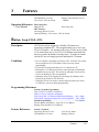
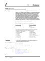
Thank you for purchasing the Panasonic Model
KX-TD816E/KX-TD1232E, Digital Super Hybrid System.
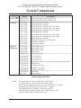
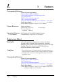
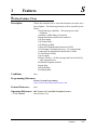
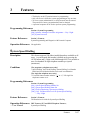
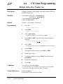
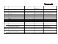
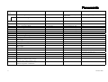
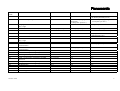
System Components
Service Unit
Telephone
Optional
Equipment
Model
Description
KX-TD816E
KX-TD1232E
KX-T7420E
KX-T7425E
KX-T7431E
KX-T7433E
KX-T7436E
KX-T7220E
KX-T7230E
KX-T7235E
KX-T7250E
KX-T7130E
KX-T7020E
KX-T7050E
KX-T7440E
KX-T7441E
KX-T7240E
KX-T7040E
KX-TD170E
KX-TD180E
KX-TD181E*1
KX-TD182E*2
KX-TD192E*1
KX-TD196E*1
KX-TD280E
KX-TD281E*1
KX-TD282E*2
KX-T30865E
KX-A46E
Digital Super Hybrid System (Main Unit)
Digital Super Hybrid System (Main Unit)
Digital proprietary telephone
Digital proprietary telephone
Digital proprietary telephone with 1-line display
Digital proprietary telephone with 3-line display
Digital proprietary telephone with 6-line display
Digital proprietary telephone
Digital proprietary telephone with 2-line display
Digital proprietary telephone with 6-line display
Digital proprietary telephone
Proprietary telephone with 1-line display
Proprietary telephone
Proprietary telephone
Digital DSS Console
Digital DSS Console
Digital DSS Console
DSS Console
8-Station Line Unit
4-CO Line Unit
8-CO Line Card
4-CO Line Card
System Inter Connection Card (two cards with Connection Cable)
Remote Card
2-ISDN S0 Line Unit
4-ISDN S0 Line Card
2-ISDN S0 Line Card
Doorphone
Battery Adaptor
System Components Table
Note
2
The models marked *1 can be installed only in KX-TD1232.
The models marked *2 can be installed only in KX-TD816.
In this Installation Manual, the suffix “E” of each model number is omitted.
The Digital Super Hybrid System is abbreviated as “DSHS.”
The Digital Proprietary Telephone is abbreviated as “DPT.”
Other proprietary telephone (analogue type) is abbreviated as “APT.”
A Single Line Telephone is abbreviated as “SLT.”
Important Information
FOR YOUR SAFETY PLEASE READ THE FOLLOWING TEXT CAREFULLY.
This appliance is supplied with a moulded three pin mains plug for your safety and convenience.
A 5 amp fuse is fitted in this plug.
Should the fuse need to be replaced please ensure that the replacement fuse has a rating of 5
amps and that it is approved by ASTA or BSI to BS1362.
Check for the ASTA mark
or the BSI mark
on the body of the fuse.
If the plug contains a removable fuse cover you must ensure that it is refitted when the fuse is
replaced.
If you lose the fuse cover the plug must not be used until a replacement cover is obtained.
A replacement fuse cover can be purchased from your local Panasonic Dealer.
IF THE FITTED MOULDED PLUG IS UNSUITABLE FOR THE SOCKET OUTLET IN
YOUR HOME THEN THE FUSE SHOULD BE REMOVED AND THE PLUG CUT OFF
AND DISPOSED OF SAFELY.
THERE IS A DANGER OF SEVERE ELECTRICAL SHOCK IF THE CUT OFF PLUG IS
INSERTED INTO ANY 13 AMP SOCKET.
If a new plug is to be fitted please observe the wiring code as shown below.
If in any doubt please consult a qualified electrician.
WARNING : THIS APPLIANCE MUST BE EARTHED.
IMPORTANT : The wires in this mains leads are coloured in accordance with the following
code:
Green-and-yellow: Earth
Blue:
Neutral
Brown:
Live
As the colours of the wires in the mains lead of this appliance may not correspond with the
coloured markings identifying the terminals in your plug, proceed as follows.
The wire which is coloured GREEN-AND-YELLOW must be connected to the terminal in the
plug which is marked with the letter E or by the safety earth symbol
or coloured GREEN or
GREEN-AND-YELLOW.
The wire which is coloured BLUE must be connected to the terminal in the plug which is marked
with the letter N or coloured BLACK.
The wire which is coloured BROWN must be connected to the terminal in the plug which is
marked with the letter L or coloured RED.
How to replace the fuse : Open the-fuse compartment with a screwdriver and replace the fuse
and fuse cover.
3
Important Information
This equipment should be used on PSTN lines requiring 2-wire Loop calling unguarded clearing
with Loop Disconnect or DTMF address signalling.
The equipment must be connected to direct extension lines and a payphone should not be
connected as an extension.
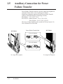
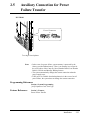
Operation in Power Failure
In the event of a power failure, three single line telephones connected to Power Failure Transfer
jacks will be directly connected to the following CO lines:
KX-TD816 — CO 1, CO 2, and CO 5
KX-TD1232 — CO 1, CO 2, and CO 9
• Set the Dialling Mode (Tone or Pulse) of your telephone, according to the CO line.
• 999 and 112 can be dialled on the apparatus for the purpose of making outgoing calls to the BT
emergency (999) and (112) service.
Satisfactory performance can not be guaranteed for every allowed combination of host and
subsidiary apparatus.
999 and 112 can be dialled on the apparatus after accessing the CO line for the purpose of
making outgoing calls to the BT emergency (999) and (112) service.
During dialling, this apparatus may tinkle the bells of other telephones using the same line. This
is not a fault and we advise you not to call Fault Repair Service.
‘Prevention of access by user. This apparatus is intended to be accessible only to authorized
personnel. This apparatus must be installed in a locked room or similar environment, such that
user access is prevented. Failure to prevent such user access will invalidate any approval given
to this apparatus.’
Caution:
Do not push the PAUSE button more than twice following the initial access digit (or digits).
Failure to comply with this requirement may result in unsatisfactory operation.
Notice:
This PBX should only be used on B•T lines on which specific BT services or facilities are
provided.
CAUTION
Danger of explosion if battery is incorrectly replaced.
Replace only with the same or equivalent type
recommended by the manufacturer.
Dispose of used batteries according
to the manufacturer's instructions.
4
Attention
• The apparatus is designed to be installed and operated under controlled conditions
of ambient temperature and a relative humidity not greater than 60%.
• Avoid installing the apparatus in damp or humid environments, such as bathrooms
or swimming pools.
• The apparatus shall not be exposed to dripping or splashing.
• Keep the unit away from heating appliances and electrical noise generating devices
such as fluorescent lamps, motors and televisions. These noise sources can
interfere with the performance of the Digital Super Hybrid System.
• This unit should be kept free of dust, moisture, high temperature (more than 40˚C /
104˚F) and vibration, and should not be exposed to direct sunlight.
• Never attempt to insert wires, pins, etc. into the vents or other holes of this unit.
• If there is any trouble, disconnect the unit from the telephone line. Plug the
telephone directly into the telephone line. If the telephone operates properly, do not
reconnect the unit to the line until the trouble has been repaired. If the telephone
does not operate properly, chances are that the trouble is in the telephone system,
and not in the unit.
• Do not use benzine, thinner, or the like, or any abrasive powder to clean the
cabinet. Wipe it with a soft cloth.
WARNING
THIS UNIT MAY ONLY BE INSTALLED AND SERVED BY QUALIFIED
SERVICE PERSONNEL.
WHEN A FAILURE OCCURS WHICH RESULTS IN THE INTERNAL PARTS
BECOMING ACCESSIBLE, DISCONNECT THE POWER SUPPLY CORD
IMMEDIATELY AND RETURN THIS UNIT TO YOUR DEALER.
DISCONNECT THE TELECOM CONNECTION BEFORE DISCONNECTING
THE POWER CONNECTION PRIOR TO RELOCATING THE EQUIPMENT,
AND RECONNECT THE POWER FIRST.
THIS UNIT IS EQUIPPED WITH AN EARTHING CONTACT PLUG. FOR
SAFETY REASONS THIS PLUG MUST ONLY BE CONNECTED TO AN
EARTHING CONTACT SOCKET WHICH HAS BEEN INSTALLED
ACCORDING TO REGULATIONS.
THE POWER SOCKET WALL OUTLET SHOULD BE LOCATED NEAR
THIS EQUIPMENT AND BE EASILY ACCESSIBLE.
TO PREVENT FIRE OR SHOCK HAZARD, DO NOT EXPOSE THIS
PRODUCT TO RAIN OR MOISTURE.
5
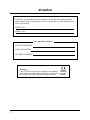
Attention
The serial number of this product may be found on the label affixed to the bottom
of the unit. You should note the serial number of this unit in the space provided
and retain this book as a permanent record of your purchase to aid in identification
in the event of theft.
MODEL NO.:
SERIAL NO.:
For your future reference
DATE OF PURCHASE
NAME OF DEALER
DEALER’S ADDRESS
Warning
This is a Class A product. In a domestic environment
this product may cause radio interference in which case
the user may be required to take adequate measures.
6
73/23/EEC
89/336/EEC
92/31/EEC
93/68/EEC
Introduction
This Installation Manual provides technical information for the Panasonic Digital
Super Hybrid System, KX-TD816/KX-TD1232. It is designed to serve as an overall
technical reference for the system and includes a description of the system, its
hardware and software, features and services and environmental requirements.
This manual contains the following sections:
Section 1, System Outline.
Provides general information on the system including system capacity and
specifications.
Section 2, Installation.
Contains the basic system installation and wiring instructions, as well as how to
install the optional cards and units.
Section 3, Features.
Describes all the basic, optional and programmable features in alphabetical order. It
also provides information about the programming required, conditions, connection
references, related features and operation for every feature.
Section 4, System Programming.
Provides step-by-step programming instructions for a proprietary telephone.
Section 5, List.
Lists tone/ring tone and default values of system programming.
Section 6, Troubleshooting.
Provides information for system and telephone troubleshooting.
Section 7, PRI Section.
Provides information on using the Primary Rate Interface (PRI) ISDN line with the
optional expansion unit.
Section 8, DECT Portable Station Section.
Provides information on the wireless system, which can be optionally equipped with
the basic system.
NOTE
The following documents may be used in conjunction with this manual:
• User Manual for KX-TD816/KX-TD1232 System, DIGITAL Proprietary Telephones,
DSS Console, DECT Portable Station and Single Line Telephones
• Programming Table
The programming table is designed to be used as a hard copy reference to the userprogrammed data.
7
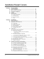
Installation Manual Contents
Section 1
1.1
1.2
1.3
1.4
1.5
Section 2
2.1
2.2
2.3
System Outline
System Highlights .............................................................................
Basic System Construction ..............................................................
Proprietary Telephones ....................................................................
Options...............................................................................................
Specifications.....................................................................................
1.5.1 General Description ..................................................................
1.5.2 Characteristics ...........................................................................
1.5.3 System Capacity........................................................................
1.5.4 Ports ..........................................................................................
1-2
1-4
1-5
1-6
1-10
1-10
1-11
1-12
1-13
Installation
Before Installation ............................................................................
Installation of the Main Unit ...........................................................
2.2.1 Unpacking .................................................................................
2.2.2 Name and Location ...................................................................
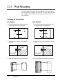
2.2.3 Wall Mounting ..........................................................................
2.2.4 Frame Earth Connection ...........................................................
2.2.5 Opening Front Cover.................................................................
Connection.........................................................................................
2.3.1 System Connection Diagram.....................................................
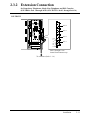
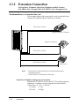
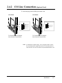
2.3.2 Extension Connection
for Proprietary Telephones, Single Line Telephones
and DSS Consoles .....................................................................................
2-2
2-4
2-4
2-4
2-6
2-7
2-7
2-8
2-8
2-10
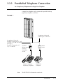
2.3.3 Parallelled Telephone Connection
for a Proprietary Telephone and a Single Line Telephone ........................
2-15
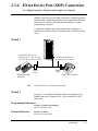
2.3.4 EXtra Device Port (XDP) Connection
for a Digital Proprietary Telephone and a Single Line Telephone ............
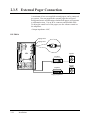
2.3.5 External Pager Connection........................................................
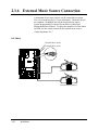
2.3.6 External Music Source Connection...........................................
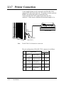
2.3.7 Printer Connection ....................................................................
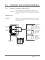
2.4 Optional Cards and Units Installation ...........................................
2.4.1 Location of Optional Cards and Units ......................................
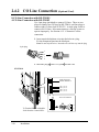
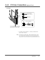
2.4.2 CO Line Connection (Optional Card) .......................................
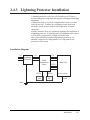
2.4.3 Lightning Protector Installation ................................................
2.4.4 CO Line Connection (Optional Unit)........................................
2.4.5 Extension Connection (Optional Unit)......................................
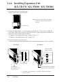
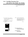
2.4.6 Installing Expansion Unit
(KX-TD170 / KX-TD180 / KX-TD280)...................................
* 2.4.7 Remote Card Installation...........................................................
2.4.8 Doorphone and Door Opener Connection.................................
8
2-17
2-18
2-20
2-22
2-25
2-25
2-28
2-35
2-38
2-38
2-39
2-42
2-43
*: Available for KX-TD1232 only.
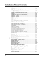
Installation Manual Contents
2.5
2.6
2.7
2.8
Section 3
A
B
C
* 2.4.9 System Connection ...................................................................
2.4.10 Battery Adaptor Connection....................................................
Auxiliary Connection for Power Failure Transfer.........................
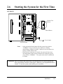
Starting the System for the First Time ...........................................
System Restart ..................................................................................
System Data Clear ............................................................................
2-48
2-50
2-52
2-54
2-56
2-57
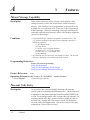
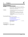
Features
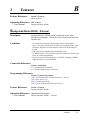
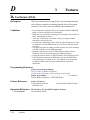
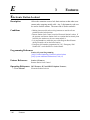
Absent Message Capability ................................................................
Account Code Entry ...........................................................................
Alert Indication...................................................................................
Alternate Calling – Ring / Voice.........................................................
Answering, Direct CO Line................................................................
Automatic Callback Busy (Camp-On) ...............................................
Automatic Configuration ....................................................................
Automatic Overflow and Hurry-Up Transfer .....................................
Automatic Redial → Redial, Automatic.............................................
Automatic Station Release..................................................................
Background Music (BGM).................................................................
Background Music (BGM) – External ...............................................
Budget Management...........................................................................
Busy Lamp Field ................................................................................
Busy Station Signalling (BSS) ...........................................................
Button, Direct Station Selection (DSS) ..............................................
Button, Flexible ..................................................................................
Button, Group-CO (G-CO).................................................................
Button, Loop-CO (L-CO) ...................................................................
Button, Single-CO (S-CO) .................................................................
Buttons on Proprietary Telephones.....................................................
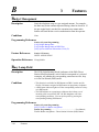
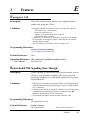
CALL FORWARDING FEATURES – SUMMARY .........................
Call Forwarding – All Calls................................................................
Call Forwarding – Busy......................................................................
Call Forwarding – Busy / No Answer ................................................
Call Forwarding – Follow Me ............................................................
Call Forwarding – No Answer............................................................
Call Forwarding – to CO Line ............................................................
Call Forwarding – by ISDN Line .......................................................
Call Hold – CO Line...........................................................................
Call Hold – Intercom ..........................................................................
Call Hold, Exclusive – CO Line .........................................................
Call Hold, Exclusive – Intercom ........................................................
*: Available for KX-TD1232 only.
3-2
3-2
3-4
3-5
3-5
3-6
3-6
3-7
3-118
3-8
3-8
3-9
3-10
3-10
3-11
3-12
3-12
3-14
3-15
3-16
3-17
3-19
3-19
3-20
3-21
3-21
3-22
3-23.0
3-23.1
3-24
3-24
3-25
3-26
9
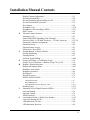
Installation Manual Contents
D
10
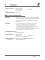
Call Hold Retrieve – CO Line ............................................................
Call Hold Retrieve – Intercom............................................................
Calling / Connected Line Identification Presentation
(CLIP / COLP) ..........................................................................
Calling Line Identification Restriction (CLIR) ..................................
Call Park .............................................................................................
Calling Party Control (CPC) Signal Detection...................................
Call Pickup, CO Line .........................................................................
Call Pickup, Directed..........................................................................
Call Pickup, Group .............................................................................
Call Pickup Deny................................................................................
Call Splitting.......................................................................................
CALL TRANSFER FEATURES – SUMMARY ...............................
Call Transfer, Screened – to CO Line.................................................
Call Transfer, Screened – to Extension ..............................................
Call Transfer, Unscreened – to Extension ..........................................
Call Waiting ........................................................................................
Charge Fee Reference.........................................................................
Class of Service (COS).......................................................................
CO Incoming Call Information Display .............................................
CO Incoming Call Information Log ...................................................
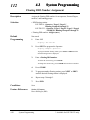
CO Line Connection Assignment.......................................................
CO Line Connection Assignment – Outgoing....................................
CO Line Group ...................................................................................
Conference..........................................................................................
Confirmation Tone..............................................................................
Connected Line Identification Restriction (COLR) ...........................
Consultation Hold...............................................................................
Data Line Security ..............................................................................
Delayed Ringing → Ringing, Delayed...............................................
Dial Tone, Distinctive .........................................................................
Dial Type Selection ............................................................................
Direct Dialling In (DDI) .....................................................................
Direct In Lines (DIL)..........................................................................
Direct Station Selection (DSS) Button
→ Button, Direct Station Selection (DSS)................................
Directed Call Pickup → Call Pickup, Directed ..................................
Display, Call Information ...................................................................
Display, Extension Programmed Data................................................
Display, Self-Extension Number ........................................................
Display, Time and Date ......................................................................
3-26
3-27.0
3-27.1
3-27.2
3-28
3-28
3-29
3-30
3-30
3-31
3-31
3-32
3-32
3-32
3-33
3-34
3-35
3-36
3-37.0
3-38
3-39
3-40
3-40
3-41
3-42
3-43
3-44
3-45
3-121
3-45
3-46
3-48.0
3-49
3-12
3-30
3-50
3-51
3-52
3-53
Installation Manual Contents
E
F
G
H
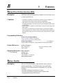
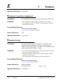
Display Contrast Adjustment..............................................................
Do Not Disturb (DND) .......................................................................
Do Not Disturb for Direct Dialling In Call.........................................
Do Not Disturb (DND) Override........................................................
Door Opener .......................................................................................
Doorphone Call...................................................................................
Doorphone Call Forwarding to ISDN ................................................
DSS Console.......................................................................................
Electronic Station Lockout .................................................................
Emergency Call ..................................................................................
End-to-End DTMF Signalling (Tone Through)..................................
Exclusive Hold → Call Hold, Exclusive – CO Line / Intercom.........
Extension Connection Assignment.....................................................
Extension Group .................................................................................
External Feature Access .....................................................................
EXtra Device Port (XDP) ...................................................................
Flexible Button → Button, Flexible ...................................................
Flexible Numbering............................................................................
Floating Station ..................................................................................
Full One-Touch Dialling.....................................................................
Group Call Pickup → Call Pickup, Group .........................................
Group CO (G-CO) Button → Button, Group-CO (G-CO).................
Handset / Headset Selection ...............................................................
Handset Microphone Mute .................................................................
Handsfree Answerback.......................................................................
Handsfree Operation...........................................................................
Hold Recall .........................................................................................
Host PBX Access................................................................................
HOTEL APPLICATION ....................................................................
3-53
3-54
3-55
3-55
3-56
3-57.0
3-57.1
3-58
3-60
3-61
3-61
3-25 / 26
3-62
3-62
3-63
3-63
3-12
3-64
3-67
3-68.0
3-30
3-14
3-68.1
3-68.1
3-69
3-69
3-70
3-71
3-72
Check-In/Check-Out........................................................................................... 3-72
Room Management............................................................................................. 3-73
Timed Reminder, Remote (Wake-Up Call) ........................................................ 3-73.0
I
L
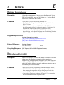
Hunting Group....................................................................................
Integrated Service Digital Network (ISDN) .......................................
Intercept Routing ................................................................................
Intercom Calling .................................................................................
ISDN Extension..................................................................................
Last Number Redial → Redial, Last Number ....................................
Least Cost Routing (LCR)..................................................................
LED Indication, CO Line ...................................................................
LED Indication, Intercom...................................................................
3-73.1
3-73.2
3-74
3-75
3-76
3-118
3-78
3-88
3-89
11
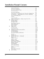
Installation Manual Contents
M
N
O
P
Q
12
Limited Call Duration.........................................................................
Line Access, Automatic......................................................................
Line Access, CO Line Group .............................................................
Line Access, Direct.............................................................................
Line Access, Individual ......................................................................
Line Preference – Incoming (No Line / Prime Line / Ringing Line) ...
Line Preference – Outgoing (Idle Line / No Line / Prime Line) ........
Live Call Screening (LCS) .................................................................
Lockout...............................................................................................
Log-In / Log-Out ................................................................................
Loop-CO (L-CO) Button → Button, Loop-CO (L-CO).....................
Manager Extension .............................................................................
Message Waiting.................................................................................
Microphone Mute ...............................................................................
Mixed Station Capacities....................................................................
Module Expansion..............................................................................
Music on Hold ....................................................................................
Night Service ......................................................................................
No Reply Group..................................................................................
Notebook Function .............................................................................
Off-Hook Call Announcement (OHCA) ............................................
Off-Hook Monitor ..............................................................................
One-Touch Dialling ............................................................................
One-Touch Transfer by DSS Button...................................................
Operator ..............................................................................................
Operator Call ......................................................................................
PAGING FEATURES – SUMMARY ................................................
Paging – All ........................................................................................
Paging – External................................................................................
Paging – Group...................................................................................
Parallelled Telephone..........................................................................
Pause Insertion, Automatic.................................................................
Phantom Extension .............................................................................
Pickup Dialling ...................................................................................
Power Failure Restart .........................................................................
Power Failure Transfer .......................................................................
Predial.................................................................................................
Private Call .........................................................................................
Pulse to Tone Conversion ...................................................................
Quick Dialling ....................................................................................
3-90
3-90
3-91
3-92
3-93
3-94
3-95
3-96
3-97
3-98
3-15
3-99
3-99
3-100
3-100
3-101
3-102
3-103
3-104.0
3-104.1
3-104.2
3-104.2
3-105
3-106
3-107
3-108
3-108
3-109
3-109
3-110
3-111
3-112.0
3-112.1
3-113
3-113
3-114
3-115
3-115
3-116
3-116
Installation Manual Contents
R
S
Recall ..................................................................................................
Redial, Automatic ..............................................................................
Redial, Last Number ..........................................................................
Redial, Saved Number .......................................................................
Remote Station Lock Control .............................................................
Reverse Circuit ...................................................................................
Ringing, Delayed ................................................................................
Ringing, Discriminating .....................................................................
Ring Group .........................................................................................
Ringing Tone Selection for CO Buttons.............................................
Ringing Tone Selection for Intercom Calls ........................................
Saved Number Redial → Redial, Saved Number...............................
Screened Call Transfer – to CO Line
→ Call Transfer, Screened – to CO Line ..................................
Screened Call Transfer – to Extension
→ Call Transfer, Screened – to Extension ................................
Secret Dialling ....................................................................................
Single-CO (S-CO) Button → Button, Single-CO (S-CO) .................
Special Display Features ....................................................................
Call Forwarding / Do Not Disturb ......................................................................
CO Outgoing Call Log .......................................................................................
Extension Dialling ..............................................................................................
Station Speed Dialling ........................................................................................
System Feature Access Menu.............................................................................
System Speed Dialling........................................................................................
Station Feature Clear ..........................................................................
Station Hunting...................................................................................
Station Message Detail Recording (SMDR) ......................................
Station Programming..........................................................................
Station Programming Data Default Set ..............................................
Station Speed Dialling ........................................................................
* System Connection .............................................................................
System Data Default Set.....................................................................
System Programming and Diagnosis with Personal Computer..........
System Programming with Proprietary Telephone.............................
System Speed Dialling........................................................................
System Working Report......................................................................
T
Terminate ............................................................................................
Time-Out, Variable ............................................................................
Timed Reminder .................................................................................
*: Available for KX-TD1232 only.
3-117
3-118
3-118
3-119
3-120
3-120
3-121
3-121
3-122
3-123.0
3-123.0
3-119
3-32
3-32
3-123.1
3-16
3-124
3-124
3-125
3-125
3-126.0
3-126.0
3-126.1
3-127
3-128.0
3-129
3-131
3-132
3-133
3-134
3-135
3-135
3-136
3-137
3-138
3-139
3-139
3-141
13
Installation Manual Contents
U
V
W
Section 4
4.1
4.2
14
Toll Restriction ...................................................................................
Toll Restriction Override by Account Code Entry .............................
Toll Restriction Override for System Speed Dialling.........................
Trunk (CO Line) Answer From Any Station (TAFAS) ......................
Two-Way Recording into the Voice Mail ...........................................
Uniform Call Distribution (UCD) ......................................................
Unscreened Call Transfer – to Extension
→ Call Transfer, Unscreened – to Extension............................
User Programming (Manager Programming).....................................
Voice Mail Integration ........................................................................
Voice Mail Integration for Digital Proprietary Telephones ................
Volume Control – Speaker / Handset Receiver / Headset / Ringer ....
Whisper OHCA ..................................................................................
3-142
3-146
3-147
3-148
3-149
3-149
3-33
3-152
3-152
3-158
3-159
3-160
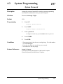
System Programming
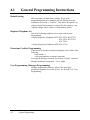
General Programming Instructions................................................
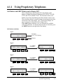
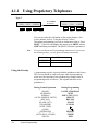
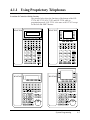
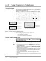
4.1.1 Using the Proprietary Telephones .............................................
4.1.2 Programming Ways ...................................................................
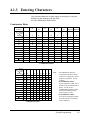
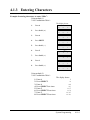
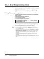
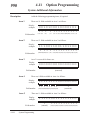
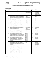
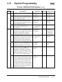
4.1.3 Entering Characters...................................................................
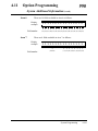
4.1.4 User Programming Mode..........................................................
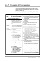
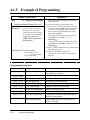
4.1.5 Example of Programming .........................................................
Manager Programming....................................................................
[000] Date and Time Set .....................................................................
[001] System Speed Dialling Number Set..........................................
[002] System Speed Dialling Name Set .............................................
[003] Extension Number Set ..............................................................
[004] Extension Name Set ..................................................................
[005] Flexible CO Button Assignment ...............................................
[006] Operator / Manager Extension Assignment — Day / Night .....
[007] DSS Console Port and Paired Telephone Assignment ..............
[008] Absent Messages.......................................................................
[009] Quick Dial Number Set.............................................................
[010] Budget Management .................................................................
[011] Charge Margin and Tax Rate.....................................................
[012] ISDN Extension Number Set ....................................................
[013] ISDN Extension Name Set........................................................
[014] Budget Management on ISDN Port ..........................................
[015] Charge Rate Fractional Point Assignment ................................
[016] Charge Rate Assignment...........................................................
4-2
4-3
4-7
4-9
4-12
4-13
4-15
4-15
4-17
4-19
4-20
4-22
4-23
4-25
4-26
4-28
4-29
4-30
4-31
4-32
4-34
4-35.0
4-35.1
4-35.2
*: Available for KX-TD1232 only.
Installation Manual Contents
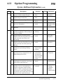
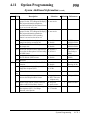
4.3
System Programming .......................................................................
[100] Flexible Numbering ..................................................................
[101] Day / Night Service Switching Mode .......................................
[102] Day / Night Service Starting Time............................................
[103] Automatic Access CO Line Group Assignment .......................
[104] Quick Dial Assignment .............................................................
[105] Account Codes ..........................................................................
[106] Station Hunting Type ................................................................
[107] System Password.......................................................................
[108] One-Touch Transfer by DSS Button .........................................
[109] Expansion Card / Unit Type ......................................................
[110] Network Type Assignment........................................................
[111] DDI Removed Digit / Added Number Assignment ..................
[112] Floating DDI Number Assignment ...........................................
[113] VM Status DTMF Set ...............................................................
[114] VM Command DTMF Set ........................................................
[115] Adjust Time...............................................................................
[116] ROM Version Display ...............................................................
[117] Charge Display Selection ..........................................................
[118] Charge Fee Reference Extension Assignment ..........................
[119] Charge Fee Reference ID Code Set ..........................................
[120] User Password ...........................................................................
[121] Pulse Dial Reception Assignment.............................................
[122] Automatic Door Open Assignment...........................................
[123] Hotel Application ......................................................................
[125] Assignment of Denomination ...................................................
[126] Voice Mail Number Assignment ...............................................
[127] Voice Mail Extension Number Assignment ..............................
[128] Voice Mail Extension Group Assignment.................................
[129] Operator Queue .........................................................................
[130] Phantom Extension Number Assignment .................................
[131] Hunting Group Assignment ......................................................
[132] Hunting Group Name Assignment............................................
[133] Hunting Overflow .....................................................................
[134]–[135] Hunting Intercept — Day / Night...................................
[136] ISDN DDI Number /
Phantom Extension Number Transformation............................
[148] Off-Hook Monitor .....................................................................
4-36
4-36
4-39
4-40
4-42.0
4-42.1
4-43
4-44
4-45
4-46
4-47
4-49.0
4-49.1
4-50
4-51
4-53
4-55
4-56
4-57
4-58
4-59
4-60
4-61
4-62
4-63
4-64
4-65
4-67
4-68
4-69.0
4-69.1
4-69.2
4-69.3
4-69.4
4-69.6
4-69.7
4-69.8
15
Installation Manual Contents
4.4
4.5
4.6
16
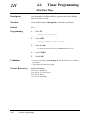
Timer Programming.........................................................................
[200] Hold Recall Time ......................................................................
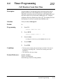
[201] Transfer Recall Time.................................................................
[202] Call Forwarding – No Answer Time.........................................
[203] Intercept Time ...........................................................................
[204] Pickup Dial Waiting Time.........................................................
[205] Extension-to-CO Line Call Duration Time...............................
[207] First Digit Time.........................................................................
[208] Inter Digit Time.........................................................................
[209] Automatic Redial Repeat Times ...............................................
[210] Automatic Redial Interval Time................................................
[211] Dial Start Time ..........................................................................
[212] Call Duration Count Start Time ................................................
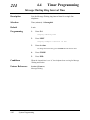
[214] Message Waiting Ring Interval Time........................................
[215] Ring-Off Detection Time ..........................................................
TRS Programming ...........................................................................
[301]–[305] TRS Denied Code Entry for Levels 2 through 6 ............
[306]–[310] TRS Excepted Code Entry for Levels 2 through 6.........
[311] Emergency Dial Number Set.....................................................
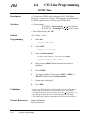
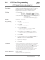
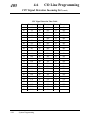
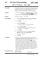
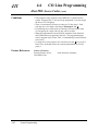
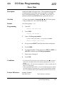
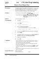
CO Line Programming ....................................................................
[400] CO Line Connection Assignment .............................................
[401] CO Line Group Assignment .....................................................
[402] Dial Mode Selection..................................................................
[403] Pulse Speed Selection ...............................................................
[404] DTMF Time ..............................................................................
[405] CPC Signal Detection Incoming Set .........................................
[407]–[408] DIL 1:1 Extension — Day / Night .................................
[409]–[410] Intercept Extension — Day / Night................................
[411] Host PBX Access Codes ...........................................................
[412] Pause Time ................................................................................
[413] Register Recall Signal Time......................................................
[414] Disconnect Time .......................................................................
[415] CPC Signal Detection Outgoing Set .........................................
[416] Reverse Circuit Assignment......................................................
[419] Subscriber Number Assignment ...............................................
[420]/[429] Direct Dialling In — Day / Night ..................................
[421] CO Line Name Assignment ......................................................
[422] ISDN Port Type.........................................................................
[423] ISDN Layer 1 Active Mode ......................................................
[424] ISDN Configuration ..................................................................
[425] ISDN Data Link Mode ..............................................................
4-70
4-70
4-71
4-72
4-73
4-74
4-75
4-76
4-77
4-78
4-79
4-80
4-81
4-82
4-83
4-84
4-84
4-85
4-86
4-87
4-87
4-88
4-89
4-91
4-92
4-93
4-95
4-96
4-97
4-99
4-100
4-101
4-102
4-103
4-104
4-105
4-106
4-107
4-108
4-109
4-110
Installation Manual Contents
4.7
4.8
[426] ISDN TEI Mode........................................................................
[427] ISDN Extension Multiple Subscriber Number .........................
[428] ISDN Extension Progress Tone.................................................
[437] Multiple Subscriber Number Set...............................................
[438]–[439] Extension Ringing Assignment
— Day / Night for ISDN MSN .................................................
COS Programming ...........................................................................
[500]–[501] Toll Restriction Level — Day / Night ............................
[502] Extension-to-CO Line Call Duration Limit ..............................
[503] Call Transfer to CO Line...........................................................
[504] Call Forwarding to CO Line .....................................................
[507] Do Not Disturb Override...........................................................
[508] Account Code Entry Mode........................................................
[509]–[510] Toll Restriction Level
for System Speed Dialling — Day / Night................................
[511] Door Opener Access .................................................................
[513] Night Service Access ................................................................
[514] Do Not Disturb for Direct Dialling In Call ...............................
[516] Calling Line Identification Restriction......................................
[517] Connected Line Identification Restriction ................................
[518] CFU / CFB / CFNR Assignment...............................................
[519] Off-Hook Call Announcement (OHCA) ...................................
Extension Programming ..................................................................
[600] EXtra Device Port .....................................................................
[601] Class of Service.........................................................................
[602] Extension Group Assignment ...................................................
[603]–[604] DIL 1:N Extension and Delayed Ringing
— Day / Night...........................................................................
[605]–[606] Outgoing Permitted CO Line Assignment
— Day / Night...........................................................................
[607]–[608] Doorphone Ringing Assignment — Day / Night ...........
[609] Voice Mail Access Codes..........................................................
[611] Extension Connection Assignment ...........................................
[612] Data Line Security.....................................................................
[613] ISDN Class of Service ..............................................................
[615]–[616] Outgoing Permitted CO Line Assignment
— Day / Night for ISDN Extension..........................................
[617] Live Call Screening Recording Mode Assignment...................
[618] ISDN DDI Number / Extension Number Transformation ........
[619] ISDN DDI Number /
ISDN Extension Number Transformation.................................
4-111
4-112
4-113.0
4-113.1
4-113.2
4-114
4-114
4-115
4-116
4-117
4-118
4-119
4-120
4-121
4-122
4-123
4-124
4-125.0
4-125.1
4-125.2
4-126
4-126
4-127
4-128
4-129
4-131
4-133
4-135
4-136
4-137
4-138
4-139
4-141
4-142.0
4-142.1
17
Installation Manual Contents
[620]–[621] Extension Intercept Routing — Day / Night..................
[622] Incoming Call Display ..............................................................
[623] CLIP / COLP Number Assignment ..........................................
[624] CLIP / COLP Number for ISDN Extension Assignment..........
[625]–[626] Doorphone Call Forwarding — Day / Night..................
4.9 LCR Programming...........................................................................
[7000] LCR Mode ..............................................................................
[7002] BTL Access Code ...................................................................
[7003] Itemized Code Set ...................................................................
[7004] Internal ISDN Itemized Code Set ...........................................
[7X0Y] LCR Leading Digit Entry for Plans 1 through 8 ...................
[7X1Y] LCR Time and Fee Set for Plans 1 through 8 .......................
[7X20] LCR Exceptional Code Set ....................................................
[7X21] LCR Carrier Code ..................................................................
[7X22] LCR Carrier Modify Command.............................................
[7X23] LCR CO Line Group Assignment..........................................
[7X24] Authorization Code Set..........................................................
4.10 Resource Programming....................................................................
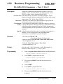
[800] SMDR Incoming / Outgoing Call Log Printout........................
[801] SMDR Format...........................................................................
[802] System Data Printout ................................................................
[803] Music Source Use .....................................................................
[804] External Pager BGM .................................................................
[805] External Pager Confirmation Tone............................................
[806]–[807] EIA (RS-232C) Parameters — Port 1 / Port 2 ...............
[813] Floating Number Assignment ...................................................
* [814] Modem Standard .......................................................................
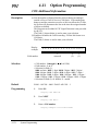
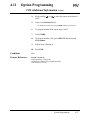
4.11 Option Programming .......................................................................
[990] System Additional Information.................................................
[991] COS Additional Information.....................................................
Section 5
5.1
5.2
Section 6
6.1
18
4-142.3
4-142.4
4-142.5
4-142.6
4-142.7
4-143
4-143
4-145
4-146.0
4-146.1
4-147
4-149
4-151
4-153
4-154
4-155
4-156
4-157
4-157
4-158
4-159
4-160
4-161
4-162
4-163
4-165
4-167
4-168
4-168
4-176
List
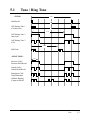
Tone / Ring Tone ............................................................................... 5-2
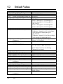
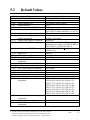
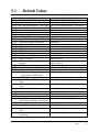
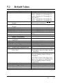
Default Values ................................................................................... 5-4
Troubleshooting
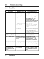
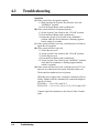
Troubleshooting ................................................................................
6.1.1 Installation.................................................................................
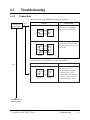
6.1.2 Connection ................................................................................
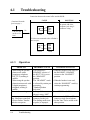
6.1.3 Operation...................................................................................
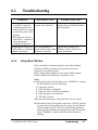
6.1.4 Using Reset Button ...................................................................
6-2
6-2
6-3
6-4
6-5
*: Available for KX-TD1232 only.
Installation Manual Contents
Section 7
7.1
7.2
7.3
Section 8
8.1
8.2
8.3
8.4
PRI Section
Overview............................................................................................
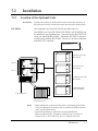
Installation.........................................................................................
7.2.1 Location of the Optional Units..................................................
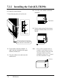
7.2.2 Installing the Unit (KX-TD290)................................................
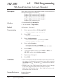
PRI System Programming ...............................................................
[450] PRI Configuration .....................................................................
[451] PRI Reference CO.....................................................................
7-2
7-3
7-3
7-5
7-7
7-7
7-9
DECT Portable Station Section
Overview............................................................................................
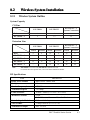
Wireless System Installation............................................................
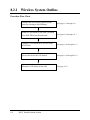
8.2.1 Wireless System Outline ...........................................................
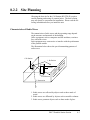
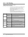
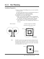
8.2.2 Site Planning .............................................................................
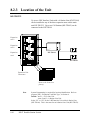
8.2.3 Location of the Unit ..................................................................
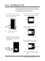
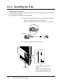
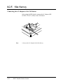
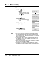
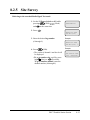
8.2.4 Installing the Unit......................................................................
8.2.5 Site Survey ................................................................................
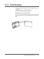
8.2.6 Wall Mounting ..........................................................................
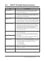
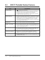
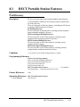
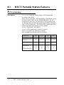
DECT Portable Station Features.....................................................
Digital Wireless Connection...............................................................
Call Directory .....................................................................................
PS Programming.................................................................................
Super EXtra Device Port (SXDP).......................................................
DECT PS System Programming .....................................................
DECT PS System Programming Conditions ......................................
[020] PS Flexible CO Button Assignment..........................................
[650] PS Registration..........................................................................
[651] PS Termination..........................................................................
[653] PS Extension Name Set.............................................................
[654] SXDP Assignment ....................................................................
[655] PS Budget Management............................................................
[656] PS Charge Verification Assignment..........................................
[657] PS Class of Service ...................................................................
[658] PS Extension Group Assignment ..............................................
[659]–[660] PS DIL 1:N Extension — Day / Night...........................
[661]–[662] PS Outgoing Permitted CO Line Assignment
— Day / Night...........................................................................
[663]–[664] PS Doorphone Ringing Assignment
— Day / Night...........................................................................
[665] PS Voice Mail Access Codes ....................................................
[667] PS Extension Connection Assignment......................................
8-2
8-3
8-3
8-5
8-9
8-11
8-16
8-27
8-28
8-28
8-33
8-34
8-36
8-38
8-38
8-39
8-41
8-44
8-46
8-47
8-48
8-49
8-50
8-51
8-52
8-54
8-56
8-57
8-58
19
Installation Manual Contents
8.5
20
[668] PS Data Line Security ...............................................................
[670] ISDN DDI Number /
PS Extension Number Transformation .....................................
[671] PS Extension Number Set .........................................................
[672] PS Password Set ........................................................................
[673] PS CLIP / COLP Number Assignment .....................................
[674]–[675] PS Extension Intercept Routing — Day / Night ............
[676] PS Incoming Call Display.........................................................
[677] PS Itemized Code Set................................................................
[681] PS Radio System ID Set............................................................
Template for the Cell Station...........................................................
8-59
8-60
8-61
8-63
8-64
8-65
8-66
8-67
8-68
8-69
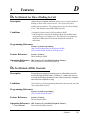
Section 1
System Outline
This section provides general information on the system,
including system capacity and specifications.
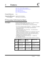
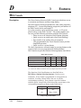
1.1
System Highlights
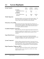
System Capacity
KX-TD816
CO line (ISDN S0 line)
Extension
KX-TD1232
CO line (ISDN S0 line)
Extension
Basic
System
Module
Expansion
System
Connection
0
8
8 (4)
16
—
—
0
16
12 (6)
32
24 (12)
64
Module Expansion
Expansion modules are used to increase the system capacity. CO
line modules and extension modules can be added to the basic
system to add CO lines, ISDN S0 lines and extensions.
EXtra Device Port (XDP)
Each extension jack in the system supports the connection of a
digital proprietary telephone / DSS console and a single line device.
The devices have different extension numbers and are treated as
two completely different extensions.
Parallelled Telephone Connection
Every jack in the system also supports the parallel connection of a
proprietary telephone and a single line device. They share the same
extension number and are considered by the system to be one
extension.
Super Hybrid System
This system supports the connection of digital and analogue
proprietary telephones, DSS Consoles and single line devices such
as single line telephones, facsimiles, and data terminals.
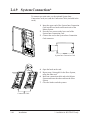
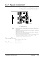
System Connection*
With the addition of optional System Inter Connection Card, two
Digital Super Hybrid Systems can be connected together to expand
the system capacity. The two systems function as one, however,
some functions such as paging and music on hold are duplicated.
Digital Proprietary Telephones (DPT)
The system supports nine different models of digital proprietary
telephones which cover the range from a monitor set to a large
display handsfree version.
1-2
System Outline
*: Available for KX-TD1232 only.
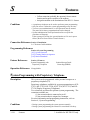
1.1
System Highlights
Programming System
The system can be programmed from a proprietary telephone or
from a personal computer.
Voice Mail Integration
The system supports Voice Processing Systems with in-band
DTMF signalling as well as DPT integration.
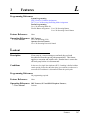
Least Cost Routing (LCR)
Automatically selects the pre-programmed least expensive route for
outgoing toll calls.
Charge Fee Reference
Allows the user to see charges and to print out the charges.
Trunk (CO Line) Answer From Any Station (TAFAS)
Ringing occurs over the external paging system; call can be
answered from any station.
Remote Station Lock Control
Allows an operator to lock an extension so that outgoing calls
cannot be made.
Budget Management
Limits the telephone usage to a pre-assigned amount.
Hotel Application
Allows to handle the front and operator services such as checkin/check-out and wake-up call setting.
Uniform Call Distribution (UCD)
Allows an incoming calls to be distributed uniformly to a specific
group of extensions.
System Outline
1-3
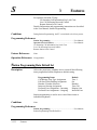
1.2
Basic System Construction
The KX-TD816 Digital Super Hybrid System has a basic capacity
of 8 extensions, and KX-TD1232 has 16 extensions. It is capable
of supporting Panasonic digital and analogue proprietary
telephones, DSS Consoles and single line devices such as single
line telephones, facsimiles.
To expand its capabilities the system can be equipped with optional
components or customer-supplied peripherals such as external
speakers and external music sources (e.g., radios).
D1232
DIGITAL SUPE
R HYBRID SYST
EM
D816
DIGITAL SUPE
R HYBRID SYST
EM
Panaso
nic
1-4
System Outline
Panaso
nic
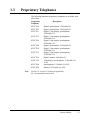
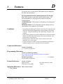
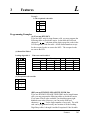
1.3
Proprietary Telephones
The following Panasonic proprietary telephones are available with
this system.
Proprietary
Telephone
KX-T7420
KX-T7425
KX-T7431
KX-T7433
KX-T7436
KX-T7220
KX-T7230
KX-T7235
KX-T7250
KX-T7130
KX-T7020
KX-T7050
Note :
Description
Digital, speakerphone, 12 Flexible CO
Digital, speakerphone, 24 Flexible CO
Digital, 1-line display, speakerphone,
12 Flexible CO
Digital, 3-line display, speakerphone,
24 Flexible CO
Digital, 6-line display, speakerphone,
24 Flexible CO
Digital, speakerphone, 24 Flexible CO
Digital, 2-line display, speakerphone,
24 Flexible CO
Digital, 6-line display, speakerphone,
12 Flexible CO
Digital, monitor, 6 Flexible CO
1-line display, speakerphone, 12 Flexible CO,
12 PF
Speakerphone, 12 Flexible CO, 4 PF
Monitor, 12 Flexible CO, 4 PF
Flexible CO : Flexible CO button (programmable)
PF : Programmable Feature button
System Outline
1-5
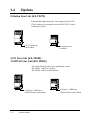
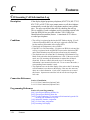
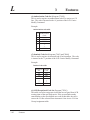
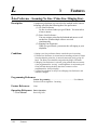
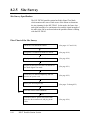
1.4
Options
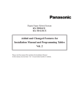
8-Station Line Unit (KX-TD170)
Each unit adds eight extensions. One expansion unit for KXTD816, and up to two expansion units for KX-TD1232 can be
installed per system.
D1232
DIGITAL SUPER HYBRID SYSTEM
D816
DIGITAL SUPER HYBRID SYSTEM
Panasonic
Panasonic
8 or 16 extensions
can be added.
8 extensions can
be added.
4-CO Line Unit (KX-TD180) /
2-ISDN S0 Line Unit (KX-TD280)
One of the following units can be installed per system.
KX-TD180 : Adds four CO lines.
KX-TD280 : Adds two ISDN S0 lines.
D1232
DIGITAL SUPER HYBRID SYSTEM
D816
DIGITAL SUPER HYBRID SYSTEM
Panasonic
Panasonic
4 CO lines / 4 DID lines /
2 ISDN S0 lines can be added.
1-6
System Outline
4 CO lines / 4 DID lines /
2 ISDN S0 lines can be added.
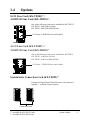
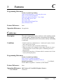
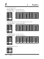
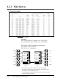
1.4
Options
8-CO Line Card (KX-TD181)*1 /
4-ISDN S0 Line Card (KX-TD281)*1
One of the following cards can be installed for KX-TD1232.
KX-TD181 : Adds eight CO lines.
KX-TD281 : Adds four ISDN S0 lines.
8 CO lines / 4 ISDN S0 lines can be added.
4-CO Line Card (KX-TD182)*2 /
2-ISDN S0 Line Card (KX-TD282)*2
One of the following cards can be installed for KX-TD816.
KX-TD182 : Adds four CO lines.
KX-TD282 : Adds two ISDN S0 lines.
4 CO lines / 2 ISDN S0 lines can be added.
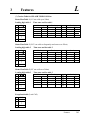
4CO/ISDN
System Inter Connection Card (KX-TD192)*1
Permits two Digital Super Hybrid Systems to be connected
together — to double system capacity.
D1232
DIGITAL SUPER
HYBRID SYSTEM
Panasonic
D1232
DIGITAL SUPER
HYBRID SYSTEM
Panasonic
Connection Cable
*1: Available for KX-TD1232 only.
*2: Available for KX-TD816 only.
System Outline
1-7
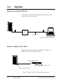
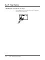
1.4
Options
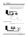
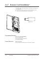
Remote Card (KX-TD196)*
The Remote Card allows programming and maintenance of the
system from a remote location.
D1232
DIGITAL SUPER
HYBRID SYSTEM
Panasonic
Central
Office
Telephone Line
Personal Computer with modem
Battery Adaptor (KX-A46)
Supports the connection of two car batteries (12 VDC✕2) for
power backup in case of a power failure.
D1232
DIGITAL SUPER
HYBRID SYSTEM
Battery Adaptor KX-A46
Panasonic
Two car batteries, connected in series
Battery Adaptor Connector
Note
1-8
System Outline
The KX-TD1232 is illustrated as a main unit.
*: Available for KX-TD1232 only.
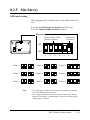
1.4
Options
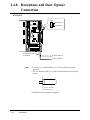
DSS Console (KX-T7440 / KX-T7441 / KX-T7240 / KX-T7040)
Permits easy and quick access to stations and features. The Busy
Lamp Field shows the idle or busy state of each station. DSS
Consoles are designed for use with a proprietary telephone. The
system supports up to four DSS Consoles per system.
D1232
DIGITAL SUPER
HYBRID SYSTEM
DIGI
TAL
Pana
sonic
DIGITA
L
Panaso
nic
Panasonic
Paired
PairedTelephone
Telephone
(Digital
Proprietary
(Proprietary
Telephone)
Telephone)
DSS
DSS Console
Console
KX-T7240/
KX-T7040
Pair
Pair
Note
The KX-TD1232 is illustrated as a main unit.
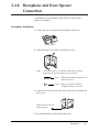
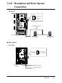
Doorphone (KX-T30865)
This system supports two doorphones and two door openers. The
doorphone is an option.
D1232
DIGITAL SUPER
HYBRID SYSTEM
Panasonic
Panasonic
Doorphone 1
Doorphone 2
Door
Opener 1
Panasonic
Note
Door
Opener 2
The KX-TD1232 is illustrated as a main unit.
System Outline
1-9
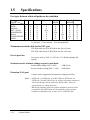
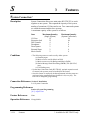
1.5
Specifications
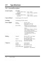
1.5.1 General Description
System Capacity
KX-TD816
CO lines (ISDN S0 lines)
Extensions
KX-TD1232
CO lines (ISDN S0 lines)
Extensions
8 max. (4 max.)
16 max. (32 max. with XDP)
12 max. (6 max.)
32 max. (64 max. with XDP)
Control Method
Stored Program CPU: 16 bits CPU
Switching
Non Blocking PCM Time Switch
Power Supplies
Primary
Secondary
Power Failure
Dialling
Outward
Internal
Mode Conversion
Connector
1-10
System Outline
CO lines
Stations
Paging Output
External Music Input
230 VAC, 50 Hz
Station Supply Volt: 30V
Circuit Volt: ± 5V, ± 15V
• Memory back-up duration: seven
years by factory-provided lithium
battery
• Power Failure Transfer: 3 CO lines
max. assigned to extensions
• System operation for several hours
by recommended batteries
(consisting of two 12 VDC car
batteries)
Dial Pulse (DP) 10 pps, 20 pps
Tone (DTMF) Dialling
Dial Pulse (DP) 10 pps, 20 pps
Tone (DTMF) Dialling
DP-DTMF, DTMF-DP
4-pin connector
6-pin connector
Pin Jack (RCA JACK)
Two-conductors Jack
(MINIJACK 3.5 mm diameter)
1.5
Specifications
Extension Connection Cable
Single line telephones
KX-T7420, KX-T7425, KX-T7431, KX-T7433,
KX-T7436, KX-T7220, KX-T7230, KX-T7235,
KX-T7250
KX-T7130 , KX-T7020, KX-T7050
KX-T7440, KX-T7441, KX-T7240, KX-T7040
1 pair wire (A, B)
1 pair wire (L, H) or
2 pair wire (A, B, L, H)
2 pair wire (A, B, L, H)
1 pair wire (L, H)
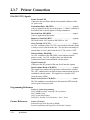
SMDR (Station Message Detail Recording)
Interface
Output Equipment
Detail Recording
1.5.2
EIA (RS-232C)
Printer
Date, Time, Extension Number, CO
Line Number, Dialled Number, Call
Duration, Charge Fee, Account Code
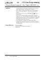
Characteristics
Station Loop Limit
KX-T7420 / KX-T7425 / KX-T7431 / KX-T7433 / KX-T7436 /
KX-T7220 / KX-T7230 / KX-T7235 / KX-T7250 / KX-T7020 /
KX-T7050 / KX-T7130 ...........................40 ohms
Single Line Telephone .............................600 ohms including set
Doorphone................................................20 ohms
Minimum Leak Resistance
15 000 ohms
Maximum Number of Station Instruments per Line
1 for KX-T7420, KX-T7425, KX-T7431, KX-T7433, KX-T7436,
KX-T7220, KX-T7230, KX-T7235, KX-T7250, KX-T7130,
KX-T7020, KX-T7050 or single line telephone
2 by Parallel or eXtra Device Port Connection of a proprietary
telephone and a single line telephone
Ring Voltage
70 Vrms at 25 Hz depends on Ringing Load
Primary Power
230 VAC, 50 Hz
Central Office Loop Limit
1 600 ohms max.
Environmental Requirements
0 – 40 °C / 32 – 104 °F, 10 – 90%
System Outline
1-11
1.5
Specifications
Ability To Recognize Further Digits
The KX-TD816 / KX-TD1232 PBX is capable of accepting and
acting upon routing information received from a proprietary
telephone for 10 seconds, after the latest routing information has
been received. (Satisfies BS6450:Part 1 1993 Clause 13.5.)
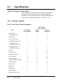
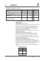
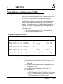
1.5.3 System Capacity
Lines, Cards, Units, Station Equipment
Item
KX-TD816
Max. Quantity
KX-TD1232
Max. Quantity
Single
System
System
Connection
System Inter
Connection Card
—
—
2
Service Unit
1
1
2
8-CO Line Card or
4-ISDN S0 Line Card
—
1
2
4-CO Line Card or
2-ISDN S0 Line Card
1
—
—
4-CO Line Unit or
2-ISDN S0 Line Unit
1
1
2
CO Line
8
12
24
ISDN S0 Line
4
6
12
8-Station Line Unit
1
2
4
Extension Jack
16
32
64
Station Terminal
(including DSS Consoles)
32
64
128
{DSS Console}
{4}
{4}
{8}
Remote Card
—
1
2
Doorphone
2
2
4
Door Opener
2
2
4
External Pager
2
2
4
External Music Source
2
2
4
1-12
System Outline
1.5
Specifications
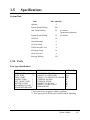
System Data
Item
Max. Quantity
Operator
2
System Speed Dialling
500
One-Touch Dialling
24
per station
(proprietary telephone)
Station Speed Dialling
10
per station
Call Park
10
Absent Message
9
CO Line Group
8
Toll Restriction Level
8
Extension Group
16
Class of Service
8
Message Waiting
128
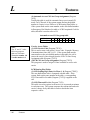
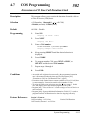
1.5.4 Ports
Port type classification
PORT NAME
BRIEF DESCRIPTION
PORT TYPE
EXTN PORT
**
PSTN PORT
**
ISDN 2 PORT
PAGING PORT
*
EXT. MUSIC PORT *
BATTERY PORT
*
DOORPHONE PORT *
DOOR OPENER PORT
CONNECT TO ITS, SLT
CONNECT TO NETWORK
CONNECT TO DIGITAL NETWORK
EXTERNAL PAGING
EXTERNAL MUSIC
CONNECT TO KX-A46
CONNECT TO KX-T30865
DOOR OPENER
1AS
PA1
PD1
4F
4F
4C
4E
4F
* These ports do not respond to address signalling.
** These ports provide DTMF and Loop Disconnect Signalling.
System Outline
1-13
1.5
Specifications
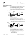
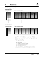
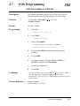
Port types between which call paths can be established
TO EXT PSTN PAGING EXT. MUSIC DOOR- Battery DOOR ISDN 2
FROM
PHONE
OPENER
A
A
A
X
EXTN
A
X
X
A
A
A
X
X
PSTN
X
X
X
X
X
X
X
X
PAGING
X
X
X
X
A
A
A
N/A
EXT. MUSIC
X
X
X
A
A
X
X
X
DOORPHONE
N/A
X
X
X
X
X
X
X
Battery
X
N/A
X
X
X
X
X
DOOR OPENER X
X
X
N/A
X
A
A
X
X
ISDN 2
X
X
X
X
A: Allowed
X: Not allowed
N/A: Not applicable
Maximum associated cable loss for EXT port
ITS: Max cable loss 0.34 dB (240 m max for ø 0.5 mm)
SLT: Max cable loss 0.87 dB (620 m max for ø 0.5 mm)
Port to port loss
Loss across switch, PAS → 1AS Loss=1.13 dB (Not through–fed
system)
Send and receive loudness ratings on port to port basis
Send loudness rating (1AS → PAS)
: +3 dB (0 km)
Receive loudness rating (PAS → 1AS) : -6 dB (0 km)
Extension (1AS) port
3 ringers can be supported with extension wiring up to 620 m.
Notes • EXTN Jack 1 to EXTN Jack 16 for KX-TD816 or EXTN Jack 1 to
EXTN Jack 32 for KX-TD1232 may be used for off premise extension in
which case cabling would be required by BS6701:Part 1 1986 to be
equipped with over voltage protection.
• When using separately approved extension telephones, the best overall
performance of the PBX system will be obtained by using extension
telephones of impedance class A clause 4.3.2.1 of BS6305:1982.
1-14
System Outline
Section 2
Installation
This section contains the basic system installation and wiring
instructions, as well as how to install the optional cards and
units.
2.1
Before Installation
Please read the following notes concerning installation and
connection before installing the system.
Safety Installation Instructions
When installing telephone wiring, basic safety precautions should
always be followed to reduce the risk of fire, electric shock and
injury to persons, including the following:
1. Never install telephone wiring during a lightning storm.
2. Never install telephone jacks in wet locations unless the jack is
specifically designed for wet locations.
3. Never touch uninsulated telephone wires or terminals unless the
telephone line has been disconnected at the network interface.
4. Use caution when installing or modifying telephone lines.
Installation Precautions
This set is exclusively made for wall mounting only. Avoid
installing in the following places. (Doing so may result in
malfunction, noise, or discoloration.)
1. In direct sunlight and hot, cold, or humid places. (Temperature
range: 0°C – 40°C / 32°F – 104°F)
2. Sulfuric gases produced in areas where there are thermal springs,
etc. may damage the equipment or contacts.
3. Places in which shocks or vibrations are frequent or strong.
4. Dusty places, or places where water or oil may come into
contact with the unit.
5. Near high-frequency generating devices such as sewing
machines or electric welders.
6. On or near computers, telexes, or other office equipment, as well
as microwave ovens or air conditioners. (It is preferable not to
install in the same room with the above equipment.)
7. Install at least 1.8 m from radios and televisions. (both the main
unit and proprietary telephones)
8. Do not obstruct area around the main unit (for reasons of
maintenance and inspection — be especially careful to allow
space for cooling above and at the sides of the main unit).
Wiring Precautions
Make sure to keep the following instructions when wiring.
1. Do not wire the telephone cable in parallel with an AC power
source, computer, telex, etc. If the cables are run near those
wires, shield the cables with metal tubing or use shielded cables
and ground the shields.
2. If cables are run on the floor, use protectors or the like to protect
2-2
Installation
2.1
Before Installation
3.
4.
5.
6.
7.
8.
9.
10.
the wires where they may be stepped on. Avoid wiring under
carpets.
Avoid using the same power supply outlet for computers,
telexes, and other office equipment. Otherwise, the system
operation may be interrupted by the induction noise from such
equipment.
Please use one pair telephone wire for extension connection of
(telephone) equipment such as single line telephones, data
terminals, answering machines, computers, voice processing
systems, etc., except proprietary telephones (e.g. KX-T7235,
KX-T7436).
The Power Switch of the system must be off during wiring.
After all the wirings are completed, turn the Power Switch on.
Mis-wiring may cause the system to operate improperly. Refer
to Section 6.1.1 “Installation” and Section 6.1.2 “Connection.”
If an extension does not operate properly, disconnect the
telephone from the extension line and then connect again, or turn
off the Power Switch of the system and then on again.
The system is equipped with a 3-wire grounding type plug. This
is a safety feature. If you are unable to insert the plug into the
outlet, contact your electrician to replace your obsolete outlet.
Do not defeat the purpose of the grounding-type plug.
Use twisted pair cable for CO line connection.
CO lines should be installed with lightning protectors. For
details, refer to Section 2.4.3 “Lightning Protector Installation.”
Warning:
Static sensitive devices are used.
To protect printed circuit boards
from static electricity, do not
touch connectors indicated to the
right. To discharge body static,
touch ground or wear a
grounding strap.
Warning : Static sensitive connectors
REMOTE
SYSTEM INTER
CONNECTION
4CO/ISDN
8CO/ISDN
Installation
2-3
2.2
Installation of the Main Unit
2.2.1
Unpacking
When you unpack the main unit, the following components should
be included:
Main Unit
AC Cord
Templet
Screw
Pager Connector
Music Source Connector
Expansion line cord holder
6-pin plugs for extension connection
4-pin plugs for doorphone or
door opener connection
Overlay
2.2.2
KX-TD816 KX-TD1232
one
one
one
one
one
one
four
three
two
two
two
two
one
one
sixteen
eight
two
one
two
one
Name and Location
Overview of the Main Unit
D1232
DIGITAL SUPE
R HYBRID SYST
EM
Earth Terminal
D816
DIGITAL SUPE
R HYBRID SYST
EM
EIA(RS-232C)
Connector
Earth Terminal
EIA (RS-232C)
Connector
Battery Adaptor
Connector
Battery Adaptor
Connector
Panaso
nic
Panaso
nic
AC Inlet
AC Inlet
Power Switch
Power Switch
Power Indicator
Power Indicator
2-4
Installation
2.2
Installation of the Main Unit
Inside View of the Main Unit
KX-TD816
Extension Connectors
4CO/ISDN
Paging Jack 2
Paging Jack 1
External Music Jack 2
External Music Jack 1
System Clear Switch
Reset Button
Door Opener and
Doorphone Connectors
Front Cover
KX-TD1232
Door Opener and
Doorphone Connectors
REMOTE
Extension Connectors
SYSTEM INTER
CONNECTION
Paging Jack 2
Paging Jack 1
External Music Jack 2
External Music Jack 1
8CO/ISDN
System Clear Switch
Reset Button
Front Cover
Notes
• EIA (RS-232C) Connector, Battery Adaptor Connector, Paging Jack
ports, External Music Jack ports, and Doorphone / Dooropener
Connectors are at SELV.
• CO Line Connectors and Extension Connections are at TNV.
• Interconnection circuit should be such that the equipment continues to
comply with the requirements of 4.2 of EN41003 for TNV circuits and
2.3 of EN60950 for SELV circuits, after making connections between
circuits.
Installation
2-5
2.2.3 Wall Mounting
This set is made exclusively for wall mounting. The wall must be
able to support the weight of the main unit. If screws other than the
ones supplied are used, they must have the same diameter as the
ones enclosed.
Mounting on Wooden Wall
KX-TD816
KX-TD1232
1. Place the templet (included) on the wall
to mark the three screw positions.
1. Place the templet (included) on the wall
to mark the four screw positions.
Templet
Templet
2. Install the three screws (included) into
the wall.
2. Install the four screws (included) into the
wall.
Wooden
Wall
Drive the screw
to this position
3. Hook the main unit on the screw heads.
2-6
Installation
Wooden
Wall
Drive the screw
to this position
3. Hook the main unit on the screw heads.
2.2
Installation of the Main Unit
2.2.4
Frame Earth Connection
IMPORTANT!!!
You must connect the frame of the main unit to Earth.
D1232
DIGITAL SUPE
R HYBRID SYSTE
M
D816
DIGITAL SUPE
R HYBRID SYSTE
M
To ground
Earth
Panas
onic
ToEarth
Earth
To
2.2.5
Opening Front Cover
Two screws are attached to the front cover by springs so that they
will not be lost. To open the front cover of the main unit:
1. Loosen the two screws on the right side of the main unit.
2. Open the front cover in the direction of Arrow A .
D1232
DIGITAL SUPE
R HYBRID SYST
EM
Screw
D816
DIGITAL SUPE
R HYBRID SYSTE
M
A
Screw
A
Screw
Screw
Panas
onic
Panas
onic
Installation
2-7
2.3
Connection
2.3.1
System Connection Diagram
D1232
DIGITAL SUPE
R HYBRID SYSTE
M
Printer for SMDR or Personal Computer for System Programming
Battery Adaptor
KX-A46
To AC Outlet
Panas
onic
Two car batteries, connected in series
• Consisting of two 12 VDC
The socket outlet shall be placed close to the
equipment and shall be easily accessible.
Panasonic
Panasonic
Door Opener 1 Door Opener 2 Doorphone 1
KX-T30865
External Music Source 1
Amplifier
Speaker 1
External Music Source 2
Amplifier
Speaker 2
Note
2-8
Doorphone 2
KX-T30865
Installation
The KX-TD1232 is illustrated as a main unit.
2.3.1 System Connection Diagram
D1232
DEGITAL SUPER HYBRID SYSTEM
(CO Lightning Protectors)
KX-TD816 : 8 CO Lines CO’s 1 through 8 (additional)
KX-TD1232: 12 CO Lines CO’s 1 through 12 (additional)
Panasonic
KX-TD816 : 16 Extensions (8 extensions – initial, 8 extensions – additional)
KX-TD1232: 32 Extensions (16 extensions – initial, 16 extensions – additional)
It is recommended that
extension of jack 1 is a
display proprietary
telephone.
(one
pair)
Single Line Telephone
DIGITAL
Panasonic
(two
pair)
KX-T7200 series digital
proprietary telephones
(one
pair)
(two pair)
KX-T7400 series digital
proprietary telephones
(two (two pair)
pair)
(one pair)
Pa
nas
oni
c
nic
aso
Pan
Cordless Phone
Data Terminal
(one
pair)
KX-T7000 series analog
proprietary telephones
(one
pair)
Digital DSS consoles
(KX-T7440/KX-T7441/
KX-T7240)
(two
pair)
(two pair)
Telephone Answering
Machine with Facsimile
Voice Processing System
Notes
KX-T7130 analog
proprietary telephone
KX-T7040 DSS console
•
: needs optional cards or adaptor.
• Parallel telephone connections are possible.
• The KX-TD1232 is illustrated as a main unit.
Installation
2-9
2.3.2 Extension Connection
for Proprietary Telephones, Single Line Telephones and DSS Consoles
(KX-TD816: Jack 1 through Jack 8, KX-TD1232: Jack 1 through Jack 16)
Wire Specifications
In making an extension line connection, use twisted pair cable for
installation. The wire specifications for extensions are as follows:
Wire
Diameter of conductor
Diameter including coating
Connection
Solid wire
ø 0.4 – ø 0.65 mm
ø 0.66 – ø 1.05 mm
Use 6-pin plugs (included). There are 8 plugs to connect extensions
to jacks 1 through 8 for KX-TD816, and 16 plugs to connect
extensions to jacks 1 through 16 for KX-TD1232. Mis-connection
may cause the system to operate improperly. See Section 6.1.1
“Installation” and 6.1.2 “Connection” before connection.
1. Insert required telephone wires into the holes in a plug.
Fix the transparent part into the black part.
Note: Do not strip the wires. Insert the wires all the way into the plug.
6-pin plug
P2
L
A
B
H
P1
2. Insert the plug into an extension jack in the main unit.
KX-TD816
Jack 4
Jack 3
4CO/ISDN
Jack 2
P2
L
A
B
H
P1
Jack 1
Jacks 1 through 8 are
located from bottom to top.
To extensions (Jacks 1 – 8)
2-10
Installation
2.3.2 Extension Connection
for Proprietary Telephones, Single Line Telephones and DSS Consoles
(KX-TD816: Jack 1 through Jack 8, KX-TD1232: Jack 1 through Jack 16)
KX-TD1232
REMOTE
Jack 4
SYSTEM INTER
CONNECTION
Jack 3
Jack 2
8CO/ISDN
P2
L
A
B
H
P1
Jack 1
Jacks 1 through 16 are
located from bottom to top.
To extensions (Jacks 1 – 16)
Installation
2-11
2.3.2 Extension Connection
for Proprietary Telephones, Single Line Telephones and DSS Consoles
(KX-TD816: Jack 1 through Jack 8, KX-TD1232: Jack 1 through Jack 16)
Maximum distance of extension line cord
The maximum length of the extension line cord, twisted cable, that
connects the main unit and the extension is as follows:
DI
GI
TA
L
Pana
so
nic
240 m for ø 0.5 mm
D1232
DIGITAL SUPER
HYBRID SYSTE
M
Digital Proprietary Telephone
Single line Telephone
620 m for ø 0.5 mm
DIGI
TAL
Pana
soni
c
240 m for ø 0.5 mm
DSS Console
Notes
• Extension line cords should only be routed internally (inside a
customers premises).
• The KX-TD1232 is illustrated as a main unit.
Proprietary Telephone (analogue type) Connection
With the KX-T7020, KX-T7050 and KX-T7130 model proprietary
telephones, 4-conductor wiring is required for each extension.
Connect pins “A,” “B,” “L” and “H.”
A: A-wire
L: Low
B: B-wire
H: High
2-12
Installation
2.3.2 Extension Connection
for Proprietary Telephones, Single Line Telephones and DSS Consoles
(KX-TD816: Jack 1 through Jack 8, KX-TD1232: Jack 1 through Jack 16)
Digital Proprietary Telephone Connection
With the KX-T7420, KX-T7425, KX-T7431, KX-T7433, KXT7436, KX-T7220, KX-T7230, KX-T7235, and KX-T7250 model
digital proprietary telephones, 4-conductor wiring is required for
each extension. Connect pins “L” and “H” only. (“A” and “B” are
only needed for Paralleled Telephone or XDP operation.)
Single Line Telephone Connection
With the single line telephones, 2-conductor wiring is required for
each extension. Connect pins “A” and “B.”
DSS Console Connection
A maximum of four DSS Consoles, models KX-T7440, KX-T7441,
KX-T7240 or KX-T7040, can be installed per system. The DSS
Console must be connected in parallel with a proprietary telephone.
System Programming is required to designate paired jack numbers
of DSS Consoles and proprietary telephones. With the KX-T7440,
KX-T7441, KX-T7240 and KX-T7040 model DSS Consoles, 4conductor wiring is required for each extension. Connect pins “L”
and “H” only. (“A” and “B” are not necessary.)
Notes
If a telephone or answering machine with an A-A1 relay is connected to
the main unit, set the A-A1 relay switch of the telephone or answering
machine to OFF position.
Station Wiring
1. Proprietary Telephone (analogue type) Connection and DSS Console
Connection
6-pin plug
Secondary socket
Terminal wire
L
A
B
H
B
L
H
A
5
4
3
2
Installation
2-13
2.3.2 Extension Connection
for Proprietary Telephones, Single Line Telephones and DSS Consoles
(KX-TD816: Jack 1 through Jack 8, KX-TD1232: Jack 1 through Jack 16)
2. Digital Proprietary Telephone Connection and SLT Connection
6-pin plug
Master socket
Terminal wire
L
A
B
H
L
B
A
H
6
5
2
1
Programming References
Section 4, System Programming,
[007] DSS Console Port and Paired Telephone Assignment
Feature References
Note
2-14
Section 3, Features,
DSS Console
After completing all the required inside cabling, including CO lines,
extensions, external pagers and external music sources, fasten the
cables with the nylon tie (included) as shown.
Installation
2.3.3 Parallelled Telephone Connection
for a Proprietary Telephone and a Single Line Telephone
A single line telephone can be connected in parallel with any
proprietary telephone as follows:
Method 1
D1232
DIGITAL SUPE
R HYBRID SYSTE
M
2-conductor wiring cord
Connect pins “A” and “B.”
4-conductor wiring cord
For DPT: Connect pins “L” and
“H” only. (“A” and “B” are not
necessary.)
For APT: Connect pins “A,”
For DPT:
“B,” “L” and “H.”
Master socket
For APT:
Secondary
socket
Digital or Analogue
Proprietary Telephone
Note
Master
socket
Single Line
Telephone
The KX-TD1232 is illustrated as a main unit.
Installation
2-15
2.3.3 Parallelled Telephone Connection
for a Proprietary Telephone and a Single Line Telephone
Method 2: for Digital Proprietary Telephone only
D1232
DIGITAL SUPER
HYBRID SYSTEM
4-conductor wiring cord
Connect pins “A,” “B,” “L” and “H.”
2-conductor wiring cord
Connect pins “A” and “B.”
Master
socket
<Back of the KX-T7400 Series DPTs>
To single line
telephone
To system
Single Line
Telephone
Digital Proprietary
Telephone
<Back of the KX-T7200 Series DPTs>
To single line
telephone
To system
LCD ADJ
PUSH
TO TEL
TO EMSS
Notes
Feature References
2-16
Installation
• Not only a single line telephone but a single line device such as an
answering machine, a facsimile or a modem (personal computer) etc.
can be connected in parallel with a digital proprietary telephone.
• The KX-TD1232 is illustrated as a main unit.
Section 3, Features,
Paralleled Telephone
2.3.4 EXtra Device Port (XDP) Connection
for a Digital Proprietary Telephone and a Single Line Telephone
With the eXtra Device Port (XDP) connection, a digital proprietary
telephone and a single line telephone can be connected to the same
extension jack and have different extension numbers. System
programming is required.
A single line telephone and a digital proprietary telephone are
connected to the main unit by 2-conductor and 4-conductor wiring
cords.
Method 1
D1232
DIGITAL SUPER
HYBRID SYSTEM
4-conductor wiring cord
Connect pins “L” and “H” only.
(“A” and “B” are not necessary.)
Master
socket
2-conductor wiring cord
Connect pins “A” and “B.”
Master
socket
Digital Proprietary
Telephone
Note
Single Line Telephone
The KX-TD1232 is illustrated as a main unit.
Method 2
Section 2.3.3 “Paralleled Telephone Connection, Method 2: for
Digital Proprietary Telephone only” is also available for XDP
connection.
Programming References
Section 4, System Programming,
[600] EXtra Device Port
Feature References
Section 3, Features,
EXtra Device Port (XDP)
Installation
2-17
2.3.5 External Pager Connection
A maximum of two user-supplied external pagers can be connected
per system. You can program the external pager that will send
background music and determine whether both pagers will generate
a confirmation tone. Use an RCA connector and shielded cable.
To adjust the sound level of the pagers, use the volume control on
the amplifiers.
• Output impedance: 600 Ω
KX-TD816
Paging Jack 2
Paging Jack 1
4CO/ISDN
Speaker
Amplifier
Paging Equipment 2
Speaker
Amplifier
Paging Equipment 1
2-18
Installation
2.3.5 External Pager Connection
KX-TD1232
REMOTE
SYSTEM INTER
CONNECTION
Paging Jack 2
Paging Jack 1
8CO/ISDN
Speaker
Amplifier
Paging Equipment 2
Speaker
Amplifier
Paging Equipment 1
Programming References
Section 4, System Programming,
[804] External Pager BGM
[805] External Pager Confirmation Tone
Feature References
Section 3, Features,
Background Music (BGM) – External Paging – External
Paging – All
Trunk (CO Line) Answer From Any Station (TAFAS)
Installation
2-19
2.3.6 External Music Source Connection
A maximum of two music sources can be connected per system.
Use a two-conductor plug (3.5 mm in diameter). Insert the plug to
the earphone / headphone jack on the external music source.
System programming is required for the Music on Hold and
Background Music features. To adjust the sound level of the Music
on Hold, use the volume control on the external music source.
• Input impedance: 8 kΩ
KX-TD816
External Music Jack 2
External Music Jack 1
4CO/ISDN
External Music Source 2
External Music Source 1
2-20
Installation
2.3.6 External Music Source Connection
KX-TD1232
REMOTE
External Music Jack 2
External Music Jack 1
SYSTEM INTER
CONNECTION
8CO/ISDN
External Music Source 2
External Music Source 1
Programming References
Section 4, System Programming,
[803] Music Source Use
[990] System Additional Information, Field (20)
Feature References
Section 3, Features,
Background Music (BGM)
Music on Hold
Background Music (BGM) – External
Installation
2-21
2.3.7 Printer Connection
A user-supplied printer can be connected to the EIA (RS-232C)
connector (25-pin) on the main unit. The printer is used to print out
SMDR call records and system programming data.
Connect the EIA (RS-232C) printer connector to the EIA
connector. Cables must be shielded; the maximum length is 2 m.
EIA
Connector
Serial Printer
Serial Interface
(RS-232C)
Note
The KX-TD1232 is illustrated as a main unit.
The pin configuration of EIA (RS-232C) connector is as follows:
Pin
No.
2-22
Installation
Signal Name
Circuit Type
EIA CCITT
1
2
FG
SD (TXD)
Frame Ground
Transmitted Data
AA
BA
101
103
3
4
RD (RXD)
RS (RTS)
Received Data
Request To Send
BB
CA
104
105
5
6
CS (CTS)
DR (DSR)
Clear To Send
Data Set Ready
CB
CC
106
107
7
8
SG
CD (DCD)
Signal Ground
Data Carrier Detect
AB
CF
102
109
20
ER (DTR)
Data Terminal
Ready
CD
108.2
2.3.7 Printer Connection
Printer / Personal Computer (25-pin) Connection Chart
EIA (RS-232C) port on
the main unit
EIA (RS-232C) port on
the printer/PC
Circuit
Type
(EIA)
Signal
Name
Pin
No.
Pin
No.
Signal
Name
Circuit
Type
(EIA)
AA
BA
FG
SD (TXD)
1
2
1
3
FG
RD (RXD)
AA
BB
BB
CB
RD (RXD)
CS (CTS)
3
5
2
SD (TXD)
BA
CC
AB
DR (DSR)
SG
6
7
20
7
ER (DTR)
SG
CD
AB
CD
ER (DTR)
20
5
6
8
CS (CTS)
DR (DSR)
CD (DCD)
CB
CC
CF
Printer / IBM Personal Computer (9-pin) Connection Chart
If you connect an IBM-PC or printer with 9-pin EIA (RS-232C)
connector to your system, see the chart below.
EIA (RS-232C) port on
the main unit
EIA (RS-232C) port on
the printer/IBM-PC
Circuit
Type
(EIA)
Signal
Name
Pin
No.
Pin
No.
Signal
Name
Circuit
Type
(EIA)
AA
BA
FG
SD (TXD)
1
2
2
RD (RXD)
BB
BB
CA
RD (RXD)
RS (RTS)
3
4
3
4
SD (TXD)
ER (DTR)
BA
CD
CB
CC
CS (CTS)
DR (DSR)
5
6
5
6
SG
DR (DSR)
AB
CC
AB
CD
SG
ER (DTR)
7
20
7
8
RS (RTS)
CS (CTS)
CA
CB
25-pin
Note
9-pin
Please read your printer manual and connect the first EIA pin (FG) of this
unit to the printer cable.
Installation
2-23
2.3.7 Printer Connection
EIA (RS-232C) Signals
Frame Ground: FG
Connects to the unit frame and the earth ground conductor of the
AC power cord.
Transmitted Data: SD (TXD) ............................................(output)
Conveys signals from the unit to the printer. A “Mark” condition is
held unless data or break signals are being transmitted.
Received Data: RD (RXD) .................................................(input)
Conveys signals from the printer.
Request to Send: RS (RTS)................................................(output)
This lead is held ‘ON’ whenever DR (DSR) is ‘ON.’
Clear To Send: CS (CTS)...................................................(input)
An ‘ON’ condition of the CS (CTS) circuit indicates that the printer
is ready to receive data from the unit. The unit does not attempt to
transfer data or receive data when the CS (CTS) circuit is ‘OFF.’
Data Set Ready: DR (DSR)................................................(input)
An ‘ON’ condition of the DR (DSR) circuit indicates that the
printer is ready. An ‘ON’ condition does not indicate that
communication has been established with the printer.
Signal Ground: SG
Connects to the DC ground of the unit for all interface signals.
Data Terminal Ready: ER (DTR) .....................................(output)
This signal line is turned on by the unit to indicate that it is online.
The ‘ON’ condition does not indicate that communication has been
established with the printer. The signal line is switched ‘OFF’
when the unit is offline.
Data Carrier Detect: CD (DCD) .......................................(input)
The ON condition is an indication to data terminal (DTE) that the
carrier signal is being received.
Programming References
Section 4, System Programming,
[800] SMDR Incoming / Outgoing Call Log Printout
[801] SMDR Format
[802] System Data Printout
[806]-[807] EIA (RS-232C) Parameters – Port 1 / Port 2
Feature References
2-24
Installation
Section 3, Features,
Station Message Detail Recording (SMDR)
System Programming and Diagnosis with Personal Computer
2.4
Optional Cards and Units Installation
2.4.1
Location of Optional Cards and Units
The location of the optional cards and units is shown below.
Precaution
To protect the printed circuit boards (P-boards) from static electricity, do
not touch parts on the P-boards in the main unit and on the optional cards
and units.
Expansion Units
KX-TD816
Either 4-CO Line Unit (KX-TD180) or 2-ISDN S0 Line Unit (KXTD280) and a 8-Station Line Unit (KX-TD170) can be installed in
any expansion area.
Expansion
area 2
8EXT
DIGITAL SUPER HYBRID SYSTEM
Expansion
area 1
4CO
DIGITAL SUPER HYBRID SYSTEM
8-Station Line
Units,
KX-TD170:
Each unit adds
eight extensions.
4-CO Line Unit,
KX-TD180:
Adds four CO
lines.
Panasonic
D816
ISDN
2SO
DIGITAL SUPER HYBRID SYSTEM
2-ISDN S0
Line Unit,
KX-TD280:
Adds two ISDN
S0 lines.
Expansion Unit
Connectors
Remove the cover
plate(s) on the front
cover.
Installation
2-25
2.4.1 Location of Optional Cards and Units
KX-TD1232
Either 4-CO Line Unit (KX-TD180) or 2-ISDN S0 Line Unit (KXTD280) and a maximum of two 8-Station Line Units (KX-TD170)
can be installed in any expansion area.
Expansion
area 3
8EXT
DIGITAL SUPER HYBRID SYSTEM
8EXT
DIGITAL SUPER HYBRID SYSTEM
Expansion
area 2
Expansion
area 1
8-Station Line
Units, KXTD170:
Each unit adds
eight extensions.
4-CO Line Unit,
KX-TD180:
Adds four CO lines.
4CO
Panasonic
DIGITAL SUPER HYBRID SYSTEM
D1232
Expansion Card
Connectors
ISDN
2SO
DIGITAL SUPER HYBRID SYSTEM
2-ISDN S0 Line
Unit, KX-TD280:
Adds two ISDN
S0 lines.
Remove the cover plates
on the front cover.
Note
2-26
Installation
System programming is required for unit location identification. Refer to
Section 4.3 [109] “Expansion Card / Unit Type.”
2.4.1 Location of Optional Cards and Units
4-CO Line Card / 2-ISDN S0 Line Card for KX-TD816
CO Line
Expansion
Card
Connector
4CO/ISDN
Install 4-CO Line Card (KX-TD182).
Adds four CO lines.
or
Install 2-ISDN S0 Line Card (KX-TD282).
Adds two ISDN S0 lines.
Front Cover
is open.
System Inter Connection Card / 8-CO Line Card / 4-ISDN S0 Line Card
for KX-TD1232
System Inter
Connection
Card
Connector
CO Line
Expansion
Card
Connector
SYSTEM INTER
CONNECTION
8CO/ISDN
Install System Inter Connection Card
(KX-TD192).
This card connects two DSHSs together.
Install 8-CO Line Card (KX-TD181).
Adds eight CO lines.
or
Install 4-ISDN S0 Line Card (KX-TD281).
Adds four ISDN S0 lines.
Front Cover
is open.
Installation
2-27
2.4.2 CO Line Connection (Optional Card)
Card Installation for KX-TD816
To connect CO 1 through CO 4, install the optional 4-CO Line
Card (KX-TD182).
To connect two ISDN S0 lines (CO 1 through CO 4), install the
optional 2-ISDN S0 Line Card (KX-TD282).
1. Insert the upper end of the 4-CO Line Card or 2-ISDN S0 Line
Card into the two hooks on the main unit.
2. Press the two corners at the lower end of the Card.
3. Fix the card with an accessory screw at the lower-right corner.
4. Connect the cord to the connector.
2-ISDN S0 Line Card
4-CO Line Card
4-pin Connector ✕ 2
4-pin Connector ✕ 1
2-28
Installation
2.4.2 CO Line Connection (Optional Card)
Card Installation for KX-TD1232
To connect CO 1 through CO 8, install the optional 8-CO Line
Card (KX-TD181).
To connect four ISDN S0 lines (CO 1 through CO 8), install the
optional 4-ISDN S0 Line Card (KX-TD281).
1. Insert the upper end of the 8-CO Line Card or 4-ISDN S0 Line
Card into the two hooks on the main unit.
2. Press the two corners at the lower end of the Card.
3. Fix the card with an accessory screw at the lower-right corner.
4. Connect the cord to the connector.
4-ISDN S0 Line Card
CO Line Expansion Card
4-pin Connector ✕ 4
4-pin Connector ✕ 1 (on the lower board)
Wire Specifications
In making a CO line connection, use twisted pair cable for
installation. The wire specifications for CO lines are as follows:
Wire
Diameter of conductor
Diameter including coating
Notes
Solid wire
ø 0.4 – ø 0.65 mm
ø 0.66 – ø 1.05 mm
• In case of starting the system for the first time or System Data Clear,
the application for location will adapt the practical installation instead
of system default setting.
• System Programming is required for location identification. Refer to
Section 4, [109] “Expansion Card / Unit Type.”
Default: CO Line Expansion Unit
Installation
2-29
2.4.2 CO Line Connection (Optional Card)
8-CO Line Connection with KX-TD181 /
4-CO Line Connection with KX-TD182
Use 4-pin plugs (included) to connect CO lines. There are two
plugs to connect four CO lines for KX-TD816, and four plugs to
connect eight CO lines for KX-TD1232. A single plug is able to
connect two CO lines. Mis-connection may cause the system to
operate improperly. See Section 6.1.2 “Connection” before
connection.
1. Insert required telephone wires into the holes in a plug.
Fix the transparent part into the black part.
Note: Do not strip the wires. Insert the wires all the way into the plug.
4-pin plug
A
B
A
B
2. Insert the plug A into a CO jack B on the card.
KX-TD181
Jacks for Power
Failure Transfer †
CO 7, CO 8
CO 5, CO 6
CO 3, CO 4
CO 1, CO 2
B
View of Connector
A
To Terminal Board or Modular
Jacks from the Central Office.
2-30
Installation
A
CO 2
B
A
CO 1
B
2.4.2 CO Line Connection (Optional Card)
KX-TD182
Jacks for Power
Failure Transfer †
CO 3, CO 4
CO 1, CO 2
View of Connector
B
A
A
CO 2
B
A
CO 1
B
To Terminal Board or Modular
Jacks from the Central Office.
† For details, refer to Section 2.5 “Auxiliary Connection for
Power Failure Transfer.”
Note: If connection is made using a TJF (Test Jack Frame), ensure
the maximum cable length between the TJF and the point on
entry into the CO card is less than 30 m (minimum distance 0 m).
Installation
2-31
2.4.2 CO Line Connection (Optional Card)
4-ISDN S0 Line Connection with KX-TD281 /
2-ISDN S0 Line Connection with KX-TD282
Use 4-pin plugs (included) to connect ISDN S0 lines. There are
two plugs to connect two ISDN S0 lines for KX-TD816, and four
plugs to connect four ISDN S0 lines for KX-TD1232. A single
plug is able to connect one ISDN S0 line. Mis-connection may
cause the system to operate improperly. See Section 6.1.2
“Connection” before connection.
Preparation
For KX-TD281 only
(Not necessary for KX-TD282.)
1. Take the appropriate jumper cover out of the first and second
pins from the left on the jumper of the P-board (“S0” side).
Jumper 1 for Port number 03
Jumper 2 for Port number 04
2. Cover the jumper cover on the first and second pins from the
right on the jumper of the P-board (“EXT” side).
Jumper 1
EXT
SO
EXT
SO
Connection
EXT
EXT
SO
SO
DIP
Jumper 2
S0: External
EXT: Internal
Use 4-pin plugs (included) to connect ISDN S0 lines. A single
plug is able to connect one ISDN S0 line. Mis-connection may
cause the system to operate improperly.
1. Re-arrange telephone wires in reverse order of the plug.
Wiring for external ISDN S0 line
2-32
Installation
Wiring for internal ISDN S0 line
TB
RB
TB
TA
TA
RA
RA
RA
TA
RB
RB
TB
2.4.2 CO Line Connection (Optional Card)
2. Insert the plug into an ISDN port on the card.
KX-TD282
KX-TD281
Port No. 4
Port No. 3
Port No. 2
Port No. 1
To Terminal Board or Modular
Jacks from the Central Office.
Port No. 2
Port No. 1
To Terminal Board or Modular
Jacks from the Central Office.
Note: If connection is made using a TJF (Test Jack Frame), ensure
the maximum cable length between the TJF and the point on
entry into the CO card is less than 30 m (minimum distance 0 m).
Installation
2-33
2.4.2 CO Line Connection (Optional Card)
Maximum cabling distance of S0 bus connection
The maximum length of the extension line cord that connects the
main unit and the ISDN terminal equipment (TE) is shown below:
Under 1000 m
D1232
DIGITAL SUPER
HYBRID SYSTEM
Point-to-Point
TE
Panasoni
c
Point-to-Multipoint
TE 1
TE 8
Under 150 m
Expansion Point-to-Multipoint
TE 1
Under 500 m
TE 8
Under 50 m
Wiring with Terminating Resistors (TR)
The ISDN S0 bus should be terminated with two 100Ω terminating
resistors (TR).
TR†
Main
Unit
TE 1
TE 8
†TR
RB
RA
TA
TB
TR 100Ω
TR 100Ω
Power Supply for ISDN Terminal Equipment (TE)
The system does not provide a power supply to terminal equipment
(TE). Depending on the type of TE's, the external power supply is
required on ISDN S0 line to operate.
2-34
Installation
2.4.3 Lightning Protector Installation
A lightning protector is a device to be installed on a CO line to
prevent a dangerous surge from entering the building and damaging
equipment.
A dangerous surge can occur if a telephone line comes in contact
with a power line. Troubles due to lightning surges have been
showing a steady increase with the development of electronic
equipment.
In many countries, there are regulations requiring the installation of
a lightning protector. A lightning strike to a telephone cable which
is 10 m above ground can be as high as 200,000 volts.
This system should be installed with lightning protectors. In
addition, connection to earth ground is very important for the
protection of the system.
Installation Diagram
CO
CO
Lightning
Protectors
CO
Main
Distribution
Frame
EXTN
SLT
Main Unit
EXTN
EXTN
PT
Earth Terminal
Frame
Earth
Earth
Installation
2-35
2.4.3 Lightning Protector Installation
Outside Installation Diagram
If you install an extension outside of the main building, the
following precautions are recommended:
(1) Install the extension wire underground.
(2) Use a conduit to protect the wire.
(Main Building)
Protectors
CO
(Another Building)
CO
CO
Main
Distribution
Frame
EXTN
Main
Unit
EXTN
SLT
PT
Lightning
Protector
EXTN
EXTN
TEL
TEL
Earth
Note
2-36
Installation
The lightning protector for an extension is different from that for CO.
2.4.3 Lightning Protector Installation
Earth Rod Installation Diagram
The length of earth rod and the required depth depend on the
composition of the soil. Consider the following recommendations:
Lightning
Protector
CO
Earth Wire
Main
Unit
(Underground)
Earth Rod
1)
2)
3)
4)
5)
Installation location of the earth rod .............Near the protector
Check obstructions........................................None
Composition of the earth rod ........................Metal
Depth of the earth rod ...................................More than 50 cm
Size of the earth wire ....................................Thickness is more
than 1.6 mm
Installation
2-37
2.4
2.4.4
Optional Cards and Units Installation
CO Line Connection (Optional Unit)
To add four CO lines (KX-TD816: CO 5 through CO 8, KXTD1232: CO 9 through CO 12), use the optional 4-CO Line Unit
(KX-TD180). To add two ISDN S0 lines, use the optional 2-ISDN
S0 Line Unit (KX-TD280). One of these units can be installed in
any of the two/three expansion areas provided on the front of the
main unit.
For Unit Installation, see Section 2.4.6 “Installing Expansion Unit
(KX-TD170/KX-TD180/KX-TD280).”
2.4.5
Extension Connection (Optional Unit)
To add eight extensions (KX-TD816: jacks 9 through 16, KXTD1232: jacks 17 through 24), use the optional 8-Station Line Unit
(KX-TD170).
To add 16 extensions (jacks 17 through 32)*, use two 8-Station
Line Units.
This unit can be installed in any of the two/three expansion areas
provided on the front of the main unit.
For Unit Installation, see Section 2.4.6 “Installing Expansion Unit
(KX-TD170/KX-TD180/KX-TD280).”
2-38
Installation
2.4.6 Installing Expansion Unit
(KX-TD170 / KX-TD180 / KX-TD280)
The following procedures can be used to install either 8-Station
Line Unit (KX-TD170), 4-CO Line Unit (KX-TD180) or 2-ISDN
S0 Line Unit (KX-TD280). There are two expansion areas for KXTD816 and three expansion areas for KX-TD1232. System
programming is required for unit location identification.
Default KX-TD816:
bottom = 4-CO Line Unit,
top = 8-Station Line Unit
KX-TD1232: bottom = 4-CO Line Unit,
middle and top = 8-Station Line Unit
Note
The KX-TD1232 is illustrated as a main unit.
1. Loosen the two the screws on the cover
plate. Insert fingers into the slits to
remove the cover plate.
D1232
DIGITAL SUPER
3. Hook the cabinet to the main unit and
slide the cabinet to the left until it is
fixed.
D1232
HYBRID SYSTE
M
DEGITAL SUPER HYBRID SYSTEM
Slit
Slit
Panasonic
Panaso
nic
Note Any of the cover plates can be
removed, as needed.
2. Connect the cabinet cord to the
connector in the main unit firmly.
D1232
4. Loosen the outside screw and slide the
cover to the right.
D1232
DIGITAL SUPER HYBRID SYSTEM
DIGITAL SUPER HYBRID SYSTEM
Panasonic
Panasonic
Outside screw
Installation
2-39
2.4.6 Installing Expansion Unit
(KX-TD170 / KX-TD180 / KX-TD280)
5. Secure the inside screw (included in the
card) to fix the cabinet to the main unit.
D1232
DIGITAL SUPER HYBRID SYSTEM
Note Be sure to fix the inside screw to the
main unit, or the unit may not work
properly.
Inside screw
Panasonic
6. Prepare the required plugs. Two 4-pin plugs are included in 4-CO Line Unit or 2-ISDN S0
Line Unit to connect four CO lines or two ISDN S0 lines. Eight 6-pin plugs are included in 8Station Line Unit to connect eight extensions.
• To prepare a 4-pin plug, perform step 1 on page 2-30 or 2-32.
• To prepare a 6-pin plug, perform step 1 on page 2-10.
7. Insert the plug into a jack on the unit.
Connect an earth wire to the earth terminal on the extension expansion unit in order to ground it.
KX-TD180
KX-TD170
Jacks for Power
Failure Transfer †
P2
L
A
B
H
P1
8
E
X
T
D
IG
IT
A
L
S
U
P
E
R
H
Y
B
R
ID
S
Y
S
TE
M
Jack
no.
Jack
no.
16 or 24
(32)
12 or 20
(28)
15 or 23
(31)
11 or 19
(27)
4C
P
FT
O
IT
A
L
S
P
E
R
P
an
as
on
10 or 18
(26)
13 or 21
(29)
9 or 17 (25)
CO5 or CO9
A
B
CO6 or CO10
rts
IG
U
14 or 22
(30)
A
B
po
D
H
2C
Y
O
B
R
ID
w
/P
FT
S
Y
S
TE
M
2C
O
CO7 or CO11
ic
CO8 or CO12
P
an
as
on
ic
Earth Terminal
To extensions
(jack numbers 9–16 /
17–24 / 25–32)
To Terminal Board or Modular
Jacks from the Central Office
† For details, refer to Section 2.5 “Auxiliary Connection for Power
Failure Transfer.”
2-40
Installation
2.4.6 Installing Expansion Unit
(KX-TD170 / KX-TD180 / KX-TD280)
11. Fix the cords to the wall at the shown
position so that the front cover can be
opened.
8. Tie up all the cords into a bundle. If
other cords are coming from the upper
cabinets, tie them, too.
9. Close the cabinet cover and secure the
outside screw.
10. Cover the cords with the cord holder
(included).
Notes • If two or three expansion units are
installed, cut the cabinet covers on
the lower cabinets to allow the cords
from upper cabinet to go down
through the cabinet covers. To guard
the cords, smooth the cut edge.
Cut here
D1232
DIGITAL SUPER HYBRID SYSTEM
Programming References
Section 4, System Programming,
[109] Expansion Card / Unit Type
Feature References
Section 3, Features,
Module Expansion
Installation
2-41
2.4.7 Remote Card Installation*
1. Insert the upper end of the Remote Card into the two hooks on
the main unit.
2. Press the two corners at the lower end of the Remote Card.
3. Connect the cord to the Remote Card connector.
KX-TD196
REMOTE
Remote Card
Programming References
Section 4, System Programming,
[107] System Password
[813] Floating Number Assignment
[814] Modem Standard
Feature References
2-42
Installation
Section 3, Features,
System Programming and Diagnosis with Personal Computer
*: Available for KX-TD1232 only.
2.4.8 Doorphone and Door Opener
Connection
A maximum of two doorphones (KX-T30865) and two door
openers is permitted.
Doorphone Installation
1. Loosen the screw to separate the doorphone into halves.
ic
ason
Pan
screw
2. Attach the base cover to the wall with two screws.
Note
Two kinds of screws are included; choose the one that is
appropriate for use depending on your wall type:
Type 1: When the doorphone plate has been
fixed to the wall.
Type 2: When you wish to install the
doorphone directly to the wall.
3. Connect the wires from the main unit to the screws located in the
front cover.
To the main unit (See the
following page.)
4. Re-attach the halves and re-install the screw.
Installation
2-43
2.4.8 Doorphone and Door Opener
Connection
Connection
Use 4-pin plugs (included) to connect doorphone or door opener. A
plug is able to connect up to two doorphones or door openers. 4conductor wiring is required.
1. Insert required wires into the holes in a plug.
Fix the transparent part into the black part.
Note: Do not strip the wires. Insert the wires all the way into the plug.
4-pin plug
Door opener 2
or
Doorphone 2
Door opener 1
or
Doorphone 1
2. Insert the plug into the connector in the main unit.
3. Connect the wires to the doorphone (1 or/and 2) or door opener
(1 or/and 2).
■ Doorphone
KX-TD816
DOORPHONE
4CO/ISDN
Panasonic
Doorphone 1
(KX-T30865)
4-conductor wiring
2-44
Installation
Doorphone 2
Doorphone 1
Panasonic
Doorphone 2
(KX-T30865)
2.4.8 Doorphone and Door Opener
Connection
KX-TD1232
DOORPHONE
REMOTE
Doorphone 2
Doorphone 1
SYSTEM INTER
CONNECTION
8CO/ISDN
4-conductor wiring
Panasonic
Panasonic
Doorphone 1
(KX-T30865)
Doorphone 2
(KX-T30865)
■ Door Opener
KX-TD816
DOOROPENER
Door opener 2
Door opener 1
4CO/ISDN
4-conductor wiring
is required.
To door opener 2
To door opener 1
Installation
2-45
2.4.8 Doorphone and Door Opener
Connection
KX-TD1232
DOOROPENER
Door opener 2
Door opener 1
REMOTE
SYSTEM INTER
CONNECTION
8CO/ISDN
4-conductor wiring
is required.
To door opener 2
To door opener 1
Notes
• For wiring, it is recommended to use UL 1015 twisted wire or the
equivalent.
• The wire should be between 1.2 and 2.4 mm in diameter including the
coating.
D=1.2–2.4 mm
• Pair the door opener with the doorphone.
2-46
Installation
2.4.8 Doorphone and Door Opener
Connection
Maximum distance of doorphone and door opener line
The maximum length of the doorphone and door opener line that
connects to the main unit is as follows:
D1232
DIGITAL SUPER
HYBRID SYSTE
120 m for ø 0.5 mm
M
Panasonic
Doorphone
KX-T30865
Panaso
nic
120 m for ø 0.5 mm
Note
Door opener
The KX-TD1232 is illustrated as a main unit.
Programming References
Section 4, System Programming,
[607–608] Doorphone Ringing Assignment — Day / Night
Feature References
Section 3, Features,
Door Opener
Doorphone Call
Installation
2-47
2.4.9 System Connection*
To connect two main units, use the optional System Inter
Connection Cards (two) and the Connection Cable (included in the
cards).
1. Insert the upper end of the System Inter Connection
Card into the two hooks on the main unit of the
Master System.
2. Press the two corners at the lower end of the
System Inter Connection Card.
3. Connect the cord to the System Inter Connection
Card connector.
KX-TD192 SYSTEM INTER CONNECTION
System Inter Connection Card
4. Open the latch on the card.
5. Repeat steps 1 through 4 for the Slave System,
using the other card.
6. Insert one connection cable end to the Master
System and insert the other end into the Slave
System.
7. Close the latches on both systems.
Connection Cable
2-48
Installation
*: Available for KX-TD1232 only.
2.4.9 System Connection*
8. Open the ROM Cover in the Slave System and set
the Master/Slave switch on the CPU card to “Slave.”
REMOTE
MASTER
8CO/ISDN
SLAVE
9. Turn the power on.
Notes
• System Connection is completed about one minute later after the power
is turned on.
• To turn the power on for the first time, refer to Section 2.6 “Starting the
System for the First Time.”
• The master and slave must have the same version software. Otherwise,
System Connection will not work properly.
• When you install an ISDN S0 Line Unit or/and Card, you should install
it to the Master System first and then the Slave System. If only
installed to the Slave System, noise may occur.
Programming References
Section 4, System Programming,
[115] Adjust Time
Feature References
Section 3, Features,
System Connection
*: Available for KX-TD1232 only.
Installation
2-49
2.4.10 Battery Adaptor Connection
User-supplied car batteries can be used as a backup power supply in
the event of a power failure. In case of power failure, the batteries
automatically maintain the power to the main unit instantly. The
optional Battery Adaptor, model KX-A46, is required.
The Battery Adaptor should not be exposed to direct sunlight.
Keep the adaptor and car batteries away from heating appliances
and fire. Place car batteries in airy place.
Connection
When connecting the battery adaptor, keep the following in mind.
• Make sure of the polarities of batteries and wires.
• Make sure do not short the batteries and wires.
• To connect the two batteries, use accessory wire.
Car batteries
Red (+)
Battery
Adaptor
+
1. Assemble the cords and two car batteries
(12VDC each) as shown.
Yellow (-)
-
12 VDC
Blue (-)
Accessory
wire
Fuse
Holder
+
-
12 VDC
D816
DIGITAL SUPER
HYBRID SYSTEM
2. Insert the plug of the battery adaptor into
the battery adaptor connector on the
main unit.
Connect the earth wire to the earth
terminal on the main unit.
Ground Wire
Panasonic
To Earth
KX-TD816
LED
Plug
Power Switch
Earth Terminal
D1232
DIGITAL SUPER
HYBRID SYSTEM
Ground Wire
3. Turn on the power switch of the battery
adaptor.
To Earth
KX-TD1232
Plug
LED
Power Switch
2-50
Installation
2.4.10 Battery Adaptor Connection
Wall Mounting
Metal Plates
Front
Screws
(big)
Wall
Bottom
Screws
(small)
Rear
Notes
• If the Power LED does not go on, check the main unit, battery adaptor,
batteries and wiring connection.
• After connection of the battery adaptor, keep the power switch on
unless when the main unit is turned off. (Batteries will discharge.)
• To charge the discharged batteries, use a proper charging unit.
• Power Fuse: (8A, 32V)✕2
If the Power LED light goes off during a power failure, the power fuse
may have been blown. To change the fuse:
Fuse Holder
B
A
C
1. Drive the accessory four small screws on
the bottom of the unit.
2. Place the metal plates so that the screw
heads insert into the slots as shown.
3. Slide the metal plates in the directions of
the arrows, and drive the screws.
4. Place the templet on the wall to mark
two screw positions, and install the big
screws into the wall.
5. Hook the battery adaptor on the screw
heads.
1. Turn the power switch off.
2. Turn the fuse holder in the direction of
Arrow B while pushing it in the direction
of Arrow A .
3. Change the fuse.
4. Turn the fuse holder in the direction of
Arrow C while pushing it in the direction
of Arrow A .
5. Turn the power switch on.
• Back-up Duration: depends on the amp-hour of the batteries used.
e.g. When using two 12 VDC batteries 20 amp-hour, maintenance-free,
car batteries, the power is maintained for about three hours.
Installation
2-51
2.5
Auxiliary Connection for Power
Failure Transfer
Power Failure Transfer connects a specific single line telephone to
selected CO line in the event of system power failure.
Single line telephones connected to the Power Failure Transfer
jacks are connected directly to following CO lines;
KX-TD816 : CO 1, CO 2, CO 5
KX-TD1232 : Master System – CO 1, CO 2, CO 9,
Slave System – CO 13, CO 14, CO 21
The Power Failure Transfer jack is on the 8-CO Line Card, 4-CO
Line Card and 4-CO Line Unit.
KX-TD181
Power Failure Transfer Jack
KX-TD180
View of Connector
A
B
View of Connector
A
B
A
B
P
an
as
on
ic
To a single line telephone
2-52
Installation
To a single line telephone
2.5
Auxiliary Connection for Power
Failure Transfer
KX-TD182
View of Connector
A
B
A
B
To a single line telephone
Notes
• In the event of a power failure, system memory is protected by the
factory-provided lithium battery. There is no memory loss except for
the saved values of the Camp-on, Saved Number Redial, Last Number
Redial, Call Park and Message Waiting features.
• The system automatically changes the current connection when the
power supply stops.
• If DC power is available from backup batteries in the event of an AC
power failure, the system does not change the current connection.
Programming References
Section 4, System Programming
[109] Expansion Card / Unit Type
Feature References
Section 3, Features,
Power Failure Transfer
Installation
2-53
2.6
Starting the System for the First Time
1. Set the power switch to “OFF.”
2. Set the system clear switch to “CLEAR.”
3. Plug the AC power cord into the system and an AC outlet.
4. Turn the power switch on.
5. Press the Reset button with a pointed tool.
(The power indicator will flash.)
6. Slide the system clear switch to “NORMAL” while the power
indicator is flashing (approximately within 10 seconds).
The system will be initialized with default values. The system will
also check the CO lines, extensions, and optional cards and units.
KX-TD816
SYSTEM
CLEAR
CLEAR
System Clear
Switch
NORMAL
RESET
Reset Button
To AC Outlet
Power Indicator
2-54
Installation
2.6
Starting the System for the First Time
KX-TD1232
SYSTEM
CLEAR
System Clear
Switch
CLEAR
NORMAL
RESET
Reset Button
To AC Outlet
Power Indicator
Notes
• After pressing the Reset button, slide the system clear switch to
“NORMAL” at step 6 while the power indicator is flashing
(approximately within 10 seconds). Otherwise, the system does not
start up with the default values.
• When System Connection is executed, the system will not accept
incoming outside calls for about 4 minutes after sliding the system
clear switch to “NORMAL.” The system needs time to establish the
LCR data.
CAUTION: Once you start up the system and if you turn the power off, do not perform the
above procedures to start the system again. Otherwise, your programmed data is
cleared. To start the system, just turn the power switch on.
Installation
2-55
2.7
System Restart
If after checking the system features you determine that the system
is not operating properly, restart the system.
Keep in mind that the following features are cleared when you
restart the system:
• Camp-on
• Call Park
The following features are cancelled when you restart the system:
• Calls on Hold
• Calls on Exclusive Hold
• Calls in progress
1. Make sure that the system clear switch is set to “NORMAL.”
2. Press the Reset button with a pointed tool.
Notes
2-56
Installation
• If the system clear switch is set to “CLEAR,” do not slide the system
clear switch to “NORMAL” within 20 seconds of pressing the Reset
button. If you do, the system programming data is reset to the default
values. (Refer to Section 2.8 “System Data Clear.”) Wait over 30
seconds after pressing the Reset button and then slide the system clear
switch to “NORMAL.”
• When System Connection is executed, the system will not accept
incoming outside calls for about 4 minutes after pressing the Reset
button. The system needs time to establish the LCR data.
• If the system still does not operate properly, please see Section 6.1.4
“Using Reset Button.”
2.8
System Data Clear
After storing or changing the system programming data, you can
clear the programming data stored in the system. The system will
restart with the default settings.
1. Slide the system clear switch to “CLEAR.”
2. Press the Reset button with a pointed tool.
3. Return the system clear switch to “NORMAL” while the power
indicator is flashing (approximately within 10 seconds).
Notes
• After pressing the Reset button, return the system clear switch to
“NORMAL” at step 3 while the power indicator is flashing
(approximately within 10 seconds). Otherwise, the system is not
cleared.
• When System Connection is executed, the system will not accept
incoming outside calls for about 4 minutes after returning the system
clear switch to “NORMAL.” The system needs time to establish the
LCR data.
Installation
2-57
Section 3
Features
This section describes every basic, optional, and
programmable features in alphabetical order. It also provides
information about the conditions, connection references,
programming required, related features, and operation for
every feature.
A
3
Features
Absent Message Capability
Description
Once set this option provides a message, on the display of the
calling extension, to show the reason for the called extension’s
absence. Nine messages can be programmed as desired which are
available for every extension user. There are six pre-programmed
default messages. Setting or cancelling a message can be done by
individual extension users but only callers with a display telephone
can receive the message.
Conditions
• Six default messages, which are changeable, are shown below. The
“%” means a parameter to be entered when assigning a message at
individual extension.
(1) Will Return Soon
(2) Gone Home
(3) At Ext %%% (extension number)
(4) Back at %% : %% (hour : minute)
(5) Out Until %% / %% (month / day)
(6) In a Meeting
• An extension user can select only one message at a time. The selected
message is displayed every time the user goes off-hook.
Pr ogramming References
Section 4, System Programming,
[008] Absent Messages
[100] Flexible Numbering, Absent message
[990] System Additional Information, Field (34)
Feature References
None
Operation References DPT Features, SLT and ISDN T
—User Manual
Absent Message Capability
elephone Features;
Account Code Entry
Description
3-2
Features
An Account Code is used to identify incoming and outgoing
outside calls for accounting and billing purposes. The account code
is appended to the Station Message Detail Recording (SMDR) call
record. For incoming outside calls, account codes are optional. For
outgoing outside calls, there are three modes available to enter an
account code: Verified-All Calls mode; Verified Toll Restriction
Override mode; and Option mode. One mode is selected for each
extension on a Class of Service basis.
3
A
Features
In Verified-All Calls mode, the user must always enter a preassigned account code when making any of the following calls
unless it has previously been stored in memory:
• Call Forwarding – to CO Line
• Last Number Redial
• Line Access
• Notebook Function
• One-Touch Dialling
• Pickup Dialling
• Saved Number Redial
• Station Speed Dialling
• System Speed Dialling
In Verified-Toll Restriction Override mode, the user can enter a preassigned account code only when the user needs to override toll
restriction.
In Option mode, the user can enter any account code if needed.
Conditions
• An account code can be stored into Memory Dialling (System / Station
Speed Dialling; Notebook Function; One-Touch Dialling; Pickup
Dialling; Call Forwarding – to CO Line).
• The Account button may be used in place of the feature number. A
flexible button on the proprietary telephone set can be programmed as
the Account button.
• Account code entry after CPC detection must be done within 15
seconds. Otherwise, SMDR call record is activated and entry becomes
impossible afterwards.
• If disconnection signal is selected in program [990], field (3) and Recall
function is enabled in field (15), the Verified-All Calls extension is
allowed to make an outside call using the same line with Recall
function.
• If an account code is appended to a call, specified display telephone
users can see the charge for the call (Charge Fee Reference).
• In any mode, emergency dial numbers stored in program [311]
“Emergency Dial Number Set” can be dialled out without an account
code entry.
• If the account code stored in location 01 of the programming table is
used, the dialled number is not printed out to SMDR (Private Call).
Programming References
Section 4, System Programming,
[005] Flexible CO Button Assignment
[100] Flexible Numbering, Account code entry
[105] Account Codes
[508] Account Code Entry Mode
[990] System Additional Information, Fields (3), (15)
Features
3-3
A
3
Features
Station Programming.......................................................User Manual,
Charge Fee Reference
Flexible Button Assignment – Account Button
Feature References
Section 3, Features,
Charge Fee Reference
Toll Restriction Override by Account Code Entry
Operation References
—User Manual
DPT Features, SLT and ISDN Telephone Features;
Account Code Entry
Alert Indication
Description
If the following situations occur, the pre-warning indication is
displayed on the proprietary telephone of Operator 1 in Day mode.
Memory: When the system finds the wrong system data, the
indication “System Data Err 1” is displayed.
Printer: When the paper of the printer for SMDR runs out or the
printer is out-of-service, the indication “Check Printer” is
displayed. Check the printer.
Connection*: When a system inter-connection error occurs and
system connection operation is interrupted, the indication
“System Link Down” is displayed. Connect the interface
between the systems and press the Reset Button on both systems.
Conditions
None
Programming Reference
No Programming required.
Feature Reference
None
Operation References
—User Manual
Operator Service Features,
Alert Indication
3-4
Features
*: Available for KX-TD1232 only.
3
A
Features
Alternate Calling – Ring / Voice
Description
This system offers two methods of Intercom Calling – Ring-Calling
and Voice-Calling. Ring-Calling informs the called party of an
incoming call with a ring tone, while the Voice-Calling uses the
calling party’s voice. The proprietary telephone user can select
tone or voice calling by station programming. If the user selects
Voice-Calling, the calling party can talk to the user immediately
after confirmation tone. The calling extension user is able to
change the calling method pre-selected once at a time by the called
extension by pressing “ ”; Ring-Calling can be switched to VoiceCalling, and vice versa. This operation is available for both
proprietary and single line telephone users during calling.
Conditions
Single line telephone users receive calls with Ring-Calling only.
Programming References
Station Programming.......................................................User Manual,
Intercom Alerting Assignment
Feature References
Section 3, Features,
Handsfree Answerback
Operation References
—User Manual
DPT Features, SLT and ISDN Telephone Features;
Alternate Calling — Ring / Voice
Answering, Direct CO Line
Description
Allows the proprietary telephone user to answer an incoming call
by simply pressing the appropriate CO button without lifting the
handset or pressing the SP-PHONE / MONITOR button.
Conditions
This feature permits the user to specify the desired line to be answered if
multiple incoming lines are ringing.
Programming References
No programming required.
Feature References
Section 3, Features,
CO Line Connection Assignment
Operation References
—User Manual
DPT Features,
Answering, Direct CO Line
Features
3-5
A
3
Features
Automatic Callback Busy (Camp-On)
Description
Allows the caller to be informed when the called party or the
selected line becomes free.
Automatic Callback – Extension
If the caller answers the callback ringing, the called extension
automatically starts ringing.
Automatic Callback – CO Line
If the caller answers the callback ringing, the line is automatically
selected to allow the user to make an outside call.
Conditions
• If the callback ringing is not answered in four rings (within 10 seconds)
the callback is cancelled.
• More than one extension user can set this function to one extension or
CO line at the same time.
Programming References
Section 4, System Programming,
[100] Flexible Numbering, Automatic callback busy cancel
Feature References
None
Operation References
—User Manual
DPT Features, SLT and ISDN Telephone Features;
Automatic Callback Busy (Camp-On)
Automatic Configuration†
Description
The system sends the VPS data which contains the extension
number configuration information and the VPS automatically
creates mailboxes with this data (Quick Setup).
Conditions
• The data is transmitted to the VPS on the lowest jack port.
• If two or more lines are connected with the VPS, the port(s) with lower
number(s) on the system need to be connected to one(s) with lower
number(s) on the VPS.
<Example>
Correct Way
#6
#2
#6
#2
#5
#1
#5
#1
DSHS
3-6
Features
Incorrect Way
VPS
DSHS
VPS
†: Available when the Digital Super Hybrid System is connected to a Digital
Proprietary Telephone capable Panasonic Voice Processing System (one
that supports digital proprietary telephone integration; e.g. KX-TVP100).
3
A
Features
Programming References
No programming required.
Feature References
None
Operation References
Not applicable.
Automatic Overflow and Hurry-Up Transfer
Description
When Operator 1 is busy and the outside call reaches the Operator
1 directly, the incoming call can be waited until the waiting queue
is over assigned number. When the incoming call is over assigned
number, the last call will be transferred to the Operator 2.
(Automatic Overflow)
Operator 1 can refer the waiting queue with the indicator of the
Hurry-Up button, and transfer the first waiting call to the preassigned extension with the Hurry-Up button. (Hurry-Up Transfer)
Conditions
• Automatic Overflow does not function in the following cases;
a) The waiting queue is set “0.”
b) Operator 2 is not set.
c) Operator 1 belongs to Station Hunting Group.
• Hurry-Up Transfer does not function in the following cases;
a) The waiting queue is set “0.”
b) Hurry-Up Button is not assigned.
c) Operator 1 belongs to Station Hunting Group.
Programming References
Section 4, System Programming,
[005] Flexible CO Button Assignment
[129] Operator Queue
Station Programming.......................................................User Manual,
Flexible Button Assignment, Hurry-Up Button
Feature References
Section 3, Features,
Operator
Operation References
—User Manual
Operator Service Features,
Automatic Overflow and Hurry-Up Transfer
Features
3-7
A/B
3
Features
Automatic Station Release
Description
After going off-hook, if an extension user fails to dial any digits
within a specified time period, the user will be disconnected from
the line after reorder tone is sent. To get a line again, the user must
go back on-hook and then off-hook.
Conditions
This function works in the following cases:
When making a call
(1)The first digit has not been dialled within 10 seconds.
(2)After a digit is dialled, the next one is not dialled within five
seconds (Intercom call only).
Programming References
Section 4, System Programming,
[207] First Digit Time
[208] Inter Digit Time
Feature References
None
Operation References
Not applicable.
Background Music (BGM)
Description
Allows the proprietary telephone user to listen to background music
from the monitor speaker on the telephone.
Conditions
• It may be required to select a music source used for BGM by system
programming.
• For Music Source 1, it is possible to select the internal or external music
source by system programming.
• The music is interrupted while off-hooked.
Connection References
Section 2, Installation,
2.3.6 External Music Source Connection
Programming References
Section 4, System Programming,
[803] Music Source Use
[990] System Additional Information, Field (20)
3-8
Features
3
B
Features
Feature References
Section 3, Features,
Music on Hold
Operation References
—User Manual
DPT Features,
Background Music (BGM)
Background Music (BGM) – External
Description
Background music (BGM) can be broadcasted in your office
through external pagers. The BGM can be turned on and off by the
operator only.
Conditions
• It is required to connect an external pager and an external music
source. The pager and the music source are user-supplied items. Up to
two pagers and up to two external music sources can be installed per
system.
• Each pager can be programmed to send BGM or not.
• For Music Source 1, it is possible to select the internal or external music
source by system programming.
• Priority of access to external pager is: (1)TAFAS; (2)Paging; (3)BGM.
Higher priorities will override BGM.
Connection References
Section 2, Installation,
2.3.5 External Pager Connection
2.3.6 External Music Source Connection
Programming References
Section 4, System Programming,
[100] Flexible Numbering, Background music – external
[803] Music Source Use
[804] External Pager BGM
[990] System Additional Information, Field (20)
Feature References
Section 3, Features,
Background Music (BGM)
Operation References
—User Manual
Operator Service Features
Background Music (BGM) — External
Features
3-9
B
3
Features
Budget Management
Description
Limit the telephone usage to a pre-assigned amount. For example,
the limit may be the amount deposited during a hotel at check-in. If
the pre-assign limit is reached, the extension user cannot make
further calls until he/she receives authorization from the operator.
Conditions
None
Programming References
Section 4, System Programming,
[010] Budget Management
[014] Budget Management on ISDN Port
[990] System Additional Information, Field (32)
Feature References
Section 3, Features,
HOTEL APPLICATION
Operation References
Not applicable.
Busy Lamp Field
Description
The LED (Light Emitting Diode) indicators of the DSS (Direct
Station Selection) buttons, each of which corresponds to a selected
extension, tell whether the corresponding extensions are idle, busy
or in Do Not Disturb (DND) mode.
Conditions
• This function is available for DSS buttons on DSS Consoles and for
flexible CO buttons assigned as DSS buttons on proprietary telephones.
• A DSS button indicator lights red if the corresponding extension is busy
or in DND mode.
• The DSS indicator on a proprietary telephone also informs you of
incoming calls except for the DIL 1:N and doorphone call to the
corresponding extensions. You can pick up calls by pressing the
corresponding flashing DSS buttons.
Programming References
Section 4, System Programming,
[005] Flexible CO Button Assignment
Station Programming.......................................................User Manual,
Flexible Button Assignment – Direct Station Selection (DSS) Button
3-10
Features
3
B
Features
Feature References
Operation References
Section 3, Features,
Button, Direct Station
Selection (DSS)
DSS Console
Not applicable.
Busy Station Signalling (BSS)
Description
When attempting to call a busy extension, Busy Station Signalling
allows you to signal the user on the phone to answer your call. The
called extension user hears a Call Waiting tone and is able to
answer the call.
Conditions
• This feature only works if the called extension has activated Call
Waiting. If it is activated, the caller will hear ringback tone.
• If the called party has been set to activate the Off-Hook Call
Announcement (OHCA) or Whisper OHCA function, the caller can
announce the call through the speaker or the handset.
• If none of three features, Call Waiting, OHCA or Whisper OHCA, is set
at the called party, the caller will hear a reorder tone.
Programming References
No programming required.
Feature References
Section 3, Features
Call Waiting
Whisper OHCA
Off-Hook Call Announcement (OHCA)
Operation References
—User Manual
DPT Features, SLT and ISDN Telephone Features;
Busy Station Signalling (BSS)
Features
3-11
B
3
Features
Button, Direct Station Selection (DSS)
Description
DSS button permits the proprietary telephone user one-touch access
to other extension users.
Conditions
• A flexible CO button on a proprietary telephone can be assigned as a
DSS button using either system or station programming.
• DSS buttons are provided on DSS Consoles with default setting.
Changing the setting is possible from the paired telephone using station
programming.
• Once a button is assigned as a DSS button, it provides Busy Lamp Field
(BLF) status.
• The mode of a DSS button on a DSS Console / proprietary telephone
can be programmed to disconnect the CO line and calls the extension or
hold and transfer the call to the extension (One-Touch Transfer by DSS
Button).
Programming References
Section 4, System Programming,
[005] Flexible CO Button Assignment
[108] One-Touch Transfer by DSS Button
Station Programming.......................................................User Manual,
Flexible Button Assignment – Direct Station Selection (DSS) Button
Feature References
Operation References
—User Manual
Section 3, Features,
Busy Lamp Field
DSS Console
One-Touch Transfer by DSS
Button
Basic Operation,
Making Calls
DPT Features,
Call Transfer – to Extension
DSS Console Features
Button, Flexible
Description
3-12
Features
The use of Flexible Buttons is determined by either system or
station programming. The following three types of Flexible
Buttons are provided on proprietary telephones (PT) and DSS
Consoles:
• Flexible CO buttons (provided on PT only)
• Flexible DSS buttons (provided on DSS Console only)
• Programmable Feature (PF) buttons
3
B
Features
The table below shows all of the features which can be assigned to
Flexible Buttons.
Button
Features to be assigned
Single CO
Group CO
Loop CO
Alert
Hurry-Up
Log-In / Log-Out
Live Call Screening†
Live Call Screening Cancel†
Direct Station Selection (DSS)
Message Waiting
Night
Phantom
Two-Way Record†
Two-Way Transfer†
Account Code Entry
Conference
FWD/DND
One-Touch Dialling
One-Touch Dialling with Auto Hold
Saved Number Redial
Terminate
Voice Mail Transfer
CO
(PT)
✔
✔
✔
✔
✔
✔
✔
✔
✔
✔
✔
✔
✔
✔
✔
✔
✔
✔
✔
✔
✔
✔
DSS
(DSS)
PF
(DSS)
✔
✔
✔
✔
✔
✔
✔
✔
✔
✔
✔
✔
✔
✔
✔
✔
✔
✔
✔
✔
✔
✔
In the table, “✔” indicates that the feature can be assigned to the button.
Conditions
• A CO line can only appear on one Single-CO button of any given
telephone. A station can only appear on one DSS button of any given
telephone or DSS Console.
• It is possible to have multiple appearances of the same Group-CO or
Loop-CO buttons on the same telephone. Incoming and outgoing calls
on the line are shown on the button in the following priority.
Single-CO > Group-CO > Loop-CO
Programming References
Section 4, System Programming,
[005] Flexible CO Button Assignment
Station Programming.......................................................User Manual,
Flexible Button Assignment
†: Available when the Digital Super Hybrid System is connected to a Digital
Proprietary Telephone capable Panasonic Voice Processing System (one
that supports digital proprietary telephone integration; e.g. KX-TVP100).
Features
3-13
B
3
Feature References
Operation References
Section 3, Features,
Buttons on Proprietary Telephones
Features
DSS Console
Not applicable.
Button, Group-CO (G-CO)
Description
To support efficient utilization of CO lines, a group of CO lines
(CO line group) can be assigned to a CO button. The function is
referred to as Group-CO (G-CO). The G-CO button works in
conjunction with the DIL 1:N feature. Any incoming call from any
CO line in the CO line group arrives at the G-CO button. To make
an outside call, the user can access an idle CO line in the group by
simply pressing the dedicated G-CO button.
Conditions
• No G-CO button is originally provided on a proprietary telephone (PT).
It is programmable on a CO button by either system or station
programming.
• It is needed to program the extension for receiving and / or originating
calls on CO lines.
• It is possible to assign the same CO line group to more than one G-CO
buttons on the same PT.
• It is possible to assign the same line to an S-CO button and to a G-CO
button.
• Immediate, delayed, no ringing or no incoming call (disable) can be
selected on an extension–CO line basis.
• The digital PT user can choose a desired ringer frequency for each GCO button by system or station programming.
Programming References
Section 4, System Programming,
[005] Flexible CO Button Assignment
[400] CO Line Connection Assignment
[401] CO Line Group Assignment
[603]–[604] DIL 1:N Extension and Delayed Ringing — Day / Night
[605]–[606] Outgoing Permitted CO Line Assignment — Day / Night
Station Programming.......................................................User Manual,
Flexible Button Assignment – Group-CO (G-CO) Button
Ringing Tone Selection for CO Buttons
Feature References
3-14
Features
Section 3, Features,
Answering, Direct CO Line
CO Line Group
Line Access, Direct
Ringing, Delayed
3
B
Features
LED Indication, CO Line
Line Access, CO Line Group
Operation References
—User Manual
Ringing Tone Selection for CO
Buttons
Basic Operation,
Making Calls
Receiving Calls
DPT Features,
Answering, Direct CO Line
Outward Dialling – Line Access, CO Line Group
Button, Loop-CO (L-CO)
Description
All CO lines can be assigned to a flexible CO button on a
proprietary telephone (PT). The assigned button serves as a LoopCO (L-CO) button. An incoming call on any CO line arrives at the
L-CO, unless there are no S-CO or G-CO buttons associated with
the line or unless the button is already in use. To make an outside
call, the PT user can simply press the dedicated L-CO button.
Conditions
• No L-CO button is originally provided on a PT. A flexible CO button
can be assigned as an L-CO button in either system or station
programming.
• It is possible to assign more than one L-CO button on a PT.
• Pressing the L-CO button provides the same operation as dialling the
automatic line access code. This results in Automatic Line Access or
Least Cost Routing (LCR), if programmed.
• Immediate, delayed, no ringing or no incoming call (disable) can be
selected on an extension–CO line basis.
• The digital PT user can choose a desired ringer frequency for each LCO button by system or station programming.
Programming References
Section 4, System Programming,
[005] Flexible CO Button Assignment
[400] CO Line Connection Assignment
[603]–[604] DIL 1:N Extension and Delayed Ringing — Day / Night
[605]–[606] Outgoing Permitted CO Line Assignment — Day / Night
Station Programming.......................................................User Manual,
Flexible Button Assignment – Loop-CO (L-CO) Button
Ringing Tone Selection for CO Buttons
Feature References
Section 3, Features,
Answering, Direct CO Line
LED Indication, CO Line
Line Access, Direct
Ringing, Delayed
Features
3-15
B
3
Line Access, Automatic
Operation References
—User Manual
Features
Ringing Tone Selection for CO
Buttons
Basic Operation,
Making Calls
Receiving Calls
DPT Features,
Outward Dialling – Line Access, Automatic
Button, Single-CO (S-CO)
Description
A Single-CO (S-CO) button is a CO line access button. This
allows the proprietary telephone user to access a specific line by
pressing an S-CO button. An incoming call can be directed to an SCO button.
Conditions
• The default setting for CO buttons is changeable. (Flexible CO
Button)
• An S-CO button provides CO line status.
• It is possible to assign one CO line to both an S-CO and a G-CO button.
• If Least Cost Routing (LCR) is set, it is overridden by an outgoing call
made by pressing the S-CO button.
• Incoming calls appear on the proprietary telephone, when an extension
is assigned as the incoming call destination and an S-CO, G-CO and/or
L-CO button is assigned.
• Immediate, delayed, no ringing or no incoming call (disable) can be
selected on an extension–CO line basis.
• The digital PT user can choose a desired ringing tone type for the S-CO
button by system or station programming.
Programming References
Section 4, System Programming,
[005] Flexible CO Button Assignment
[400] CO Line Connection Assignment
[603]–[604] DIL 1:N Extension and Delayed Ringing — Day / Night
[605]–[606] Outgoing Permitted CO Line Assignment — Day / Night
Station Programming.......................................................User Manual,
Flexible Button Assignment – Single-CO (S-CO) Button
Ringing Tone Selection for CO Buttons
Feature References
3-16
Features
Section 3, Features,
Answering, Direct CO Line
LED Indication, CO Line
Line Access, Direct
Line Access, Individual
Ringing, Delayed
Ringing Tone Selection for CO
Buttons
3
B
Features
Operation References
—User Manual
Basic Operation,
Making Calls
Receiving Calls
DPT Features,
Outward Dialling – Line Access, Individual
Buttons on Proprietary Telephones
Description
Proprietary telephones are provided with the feature / line access
buttons listed below:
KX-T Proprietary Telephones:
Buttons
7020 7050 7130 7220 7230 7235 7250 7420 7425 7431 7433 7436
AUTO ANSWER / MUTE † ✔
✔
AUTO DIAL / STORE †
✔ (12)
CO † *
CONF †
✔
FLASH / RCL
Function
FWD / DND †
✔
HOLD
✔
INTERCOM †
✔
Jog Dial
MESSAGE †
✔
MODE
MONITOR
PAUSE
✔
PF (Programmable Feature) ✔ (4)
PROGRAM
RECALL
✔
REDIAL
✔
SAVE
SELECT
SHIFT †
Soft
SP-PHONE †
✔
TRANSFER
✔
VOLUME
✔
†
*
!
(x)
✔
✔ (12)
✔!
✔
✔
✔
✔†
✔
✔ (4)
✔
✔
✔
✔
✔
✔
✔
✔
✔
✔
✔
✔
✔
✔
✔
✔
✔
✔
✔
✔
✔
✔!
✔ (12) ✔ (24) ✔ (24) ✔ (12) ✔ (6) ✔ (12) ✔ (24) ✔ (12) ✔ (24) ✔ (24)
✔
✔
✔
✔
✔
✔
✔
✔
✔
✔
✔
✔
✔
✔
✔ (10)
✔ (10)
✔
✔
✔
✔
✔
✔
✔
✔
✔
✔
✔
✔
✔
✔
✔
✔
✔
✔
✔
✔
✔
✔
✔
✔
✔
✔
✔
✔
✔
✔
✔
✔
✔
✔
✔
✔
✔
✔
✔
✔
✔
✔
✔
✔
✔
✔
✔
✔
✔
✔
✔
✔
✔
✔ (12)
✔
✔
✔
✔
✔
✔
✔
✔
✔
✔
✔
✔
✔
✔
✔
✔
✔
✔
✔
✔
✔
✔
✔
✔
✔
✔
✔
✔
✔
✔
✔ (3) ✔ (3)
✔ (3) ✔ (3)
✔
✔
✔
✔
✔
✔
✔
✔
✔
✔
✔
✔
✔
✔
✔
✔
✔
✔
✔
✔
✔
✔
✔
: The button is provided on the designated telephones.
: The button is provided with an LED (Light Emitting Diode).
: The buttons which can be changed to function as a feature button are called flexible buttons.
: The button is provided without an LED.
: Shows the number of buttons only if multiple buttons are provided.
Features
3-17
B
3
Features
The functions of the listed buttons are described below:
AUTO ANSWER / MUTE: This dual function button is used for
extension auto-answer and microphone mute during a conversation.
AUTO DIAL / STORE: Used for System Speed Dialling and
storing program changes.
CO (Central Office line): Can make or receive an outside call or
can be re-assigned to a different CO or to various feature buttons.
CONF (Conference): Used to establish a three-party conference.
FLASH/RCL: Allows you to disconnect the current call and
originate another call without hanging up (Recall). Sends a
Register Recall signal to the Central Office or a host PBX to access
their features (External Feature Access).
Function: Used to perform the displayed function / operation.
FWD / DND (Call Forwarding / Do Not Disturb): Used to
program Call Forwarding, set Do Not Disturb.
HOLD: Used to place a call on hold.
INTERCOM: Used to make or receive intercom calls.
Jog Dial: Used to adjust the ringer, speaker, handset and headset
volume and the display contrast. With the KX-T7431, KX-T7433
and KX-T7436, it can also be used to select data from the Call
Directory and the System Feature Access Menu on the display.
MESSAGE: Used to send a message or display current message.
MODE: Used to shift the display in order to access various
features.
MONITOR: Used for handsfree operation.
PAUSE: Inserts a pause in a speed dial number. With an analogue
proprietary telephone, it is used as the PROGRAM button.
PF (Programmable Feature): This flexible button can be
programmed to be a One-Touch Dialling, FWD / DND, SAVE,
Account, CONF (Conference) or Voice Mail Transfer button, as
desired.
PROGRAM: Used to enter / exit the Programming mode. With
the KX-T7220 and KX-T7250, it can also be used as the PAUSE
button.
RECALL: Allows you to disconnect the current call and originate
another call without hanging up (Recall). Sends a Register Recall
signal to the Central Office or a host PBX to access their features
(External Feature Access).
REDIAL: Used for Last Number or Automatic Redial.
SAVE: Used to store a dialled telephone number for Saved Number
Redial.
SELECT: Used to select the displayed function or to call for the
displayed phone number.
3-18.0
Features
3
C
Features
SHIFT: Used to access the second level of Soft button function.
Soft: Pressing a Soft button performs the function / operation
appearing on the bottom line of the display.
SP-PHONE (Speakerphone): Used for handsfree operation.
Pressing the button causes the telephone to switch between handset
and handsfree operation.
TRANSFER: Transfers a call to another extension or external
destination.
VOLUME: Used to adjust the ringer, speaker, handset and headset
volume and the display contrast.
Conditions
• Certain buttons are equipped with light indicators (LED’s) to show line
or feature status.
• CO buttons can be classified according to the following three types:
Single-CO (S-CO) button / Group-CO (G-CO) button / Loop-CO (LCO) button
Programming References
Section 4, System Programming,
[005] Flexible CO Button Assignment
Station Programming.......................................................User Manual,
Flexible Button Assignment
Feature References
None
Operation References
—User Manual
Refer to respective operating instructions.
Features
3-18.1
Page left blank for future upgrade(s)
3
C
Features
CALL FORWARDING FEATURES – SUMMARY
Description
Call forwarding features enable you to have your calls forwarded to
a specified destination. You may specify the circumstances under
which your calls are forwarded. The following Call Forwarding
features are available:
Call Forwarding – All Calls
Call Forwarding – Busy
Call Forwarding – Busy / No Answer
Call Forwarding – Follow Me
Call Forwarding – No Answer
Call Forwarding – to CO Line
Call Forwarding – by ISDN Line
Call Forwarding – All Calls
Description
This feature is used when you want all your calls to be
automatically re-directed to another extension.
Conditions
• Types of calls which are forwarded by this feature are:
Outside calls – DDI; DIL 1:1; DIL 1:N; Intercept Routing
Intercom calls – Extension; Transfer
• There can only be one stage of Call Forwarding, if a call is forwarded to
an extension which is also in Call Forwarding. In this case, Station
Hunting can be activated for the forwarded call.
• Although calls are forwarded, Message Waiting is not. The MESSAGE
button indicator is lit on the originally called extension.
• If an extension in Call Forwarding is also in a Hunt group, a call
directed to the extension is forwarded. Station Hunting still applies for
calls directed to other extensions in the Hunt group.
• Setting this function cancels other Call Forwarding or Do Not Disturb
functions, if any.
• A Floating Station cannot be programmed as the forwarded destination.
• An ISDN extension can be programmed as the forwarded destination.
Programming References
Section 4, System Programming,
[005] Flexible CO Button Assignment
[100] Flexible Numbering, Call forwarding / Do not disturb
Station Programming.......................................................User Manual,
Flexible Button Assignment – FWD/DND Button
Feature References
None
Features
3-19
C
3
Operation References
—User Manual
Features
DPT Features, SLT and ISDN Telephone Features;
Call Forwarding — All Calls
Call Forwarding – Busy
Description
A call directed to your extension is forwarded to another extension
if your telephone is busy.
Conditions
• Types of calls which are forwarded by this feature are:
Outside calls – DDI; DIL 1:1; DIL 1:N; Intercept Routing
Intercom calls – Extension; Transfer
• There can only be one stage of Call Forwarding, if a call is forwarded to
a station which is also in Call Forwarding. In this case, Station Hunting
is activated for the forwarded call.
• Although calls are forwarded, Message Waiting is not. The MESSAGE
button indicator is lit on the originally called extension.
• If an extension in Call Forwarding is also in a Hunt group, a call
directed to the extension is forwarded. Station Hunting still applies for
calls directed to other extensions in the Hunt group.
• Setting this function cancels other Call Forwarding or Do Not Disturb
functions, if any.
• A Floating Station cannot be programmed as the forwarded destination.
• An ISDN extension can be programmed as the forwarded destination.
Programming References
Section 4, System Programming,
[005] Flexible Button Assignment
[100] Flexible Numbering, Call forwarding / Do not disturb
Station Programming.......................................................User Manual,
Flexible Button Assignment – FWD/DND Button
Feature References
None
Operation References
—User Manual
DPT Features, SLT and ISDN Telephone Features;
Call Forwarding — Busy
3-20
Features
3
C
Features
Call Forwarding – Busy / No Answer
Description
Your calls are forwarded to another extension if your extension is
busy or you do not answer the call in a pre-determined time.
Conditions
• Types of calls which are forwarded by this function are:
Outside calls – DDI; DIL 1:1; DIL 1:N; Intercept Routing
Intercom calls – Extension; Transfer
• This function operates the same way as Call Forwarding – Busy and
Call Forwarding – No Answer.
• There can only be one stage of Call Forwarding if a call is forwarded to
a station which is also in Call Forwarding. In this case, Station Hunting
is activated for the forwarded call.
• Although calls are forwarded, Message Waiting is not. The MESSAGE
button indicator is lit on the originally called extension.
• If an extension in Call Forwarding is also in a Hunt group, a call
directed to the extension is forwarded. Station Hunting still applies for
calls directed to other extensions in the Hunt group.
• Setting this function cancels other Call Forwarding or Do Not Disturb
functions, if any.
• A Floating Station cannot be programmed as the forwarded destination.
• An ISDN extension can be programmed as the forwarded destination.
Programming References
Section 4, System Programming,
[005] Flexible CO Button Assignment
[100] Flexible Numbering, Call forwarding / do not disturb
[202] Call Forwarding – No Answer Time
Station Programming.......................................................User Manual,
Flexible Button Assignment – FWD/DND Button
Feature References
Operation References
—User Manual
Section 3, Features,
Call Forwarding – Busy
Call Forwarding – No Answer
DPT Features, SLT and ISDN Telephone Features;
Call Forwarding — Busy / No Answer
Call Forwarding – Follow Me
Description
If you forget to set Call Forwarding – All Calls before you leave
your desk, this allows you to set the same function from the
destination extension.
Conditions
• Same as the conditions of Call Forwarding – All Calls.
• It is programmable to enable or disable this feature on a Class of
Service basis.
Features
3-21
C
3
Features
Programming References
Section 4, System Programming,
[005] Flexible CO Button Assignment
[100] Flexible Numbering, Call forwarding / do not disturb
[991] COS Additional Information, Field (2)
Station Programming.......................................................User Manual,
Flexible Button Assignment – FWD / DND Button
Feature References
Section 3, Features,
Call Forwarding – All Calls
Operation References
—User Manual
DPT Features, SLT and ISDN Telephone Features;
Call Forwarding — Follow Me
Call Forwarding – No Answer
Description
Calls to your extension are forwarded to another extension if you
do not answer the call in a pre-determined time.
Conditions
• Types of calls which are forwarded by this function are:
Outside calls – DDI; DIL 1:1; DIL 1:N; Intercept Routing
Intercom calls – Extension; Transfer
• This function operates if an incoming call is not answered in a specific
period of time. Therefore, this function also applies if your extension is
busy and cannot answer the incoming call within the time.
• There can only be one stage of Call Forwarding if a call is forwarded to
a station which is also in Call Forwarding. In this case, Station Hunting
is activated for the forwarded call.
• Although calls are forwarded, Message Waiting is not. The MESSAGE
button indicator is lit on the originally called extension.
• If an extension in Call Forwarding is also in a Hunt group, a call
directed to the extension is forwarded. Station Hunting still applies for
calls directed to other extensions in the Hunt group.
• Setting this function cancels other Call Forwarding or Do Not Disturb
functions, if any.
• A Floating Station cannot be programmed as the forwarded destination.
• An ISDN extension can be programmed as the forwarded destination.
Programming References
Section 4, System Programming,
[005] Flexible CO Button Assignment
[100] Flexible Numbering, Call forwarding / do not disturb
[202] Call Forwarding – No Answer Time
Station Programming.......................................................User Manual,
Flexible Button Assignment – FWD/DND Button
3-22
Features
3
C
Features
Feature References
None
Operation References
—User Manual
DPT Features, SLT and ISDN Telephone Features;
Call Forwarding — No Answer
Call Forwarding – to CO Line
Description
Calls directed to your extension will be sent to an external
destination. The outside telephone number must be preprogrammed.
Conditions
• Types of calls which are forwarded by this function are:
Outside calls – DIL 1:1; DDI (ISDN Service only)
Intercom calls – Extension; Transfer
A call between two external parties can be established by this feature
only when both outside lines are ISDN S0 lines.
• The forwarding extension’s Toll Restriction, Least Cost Routing and
Account Code Entry requirements still apply.
• Although calls are forwarded, Message Waiting is not. The MESSAGE
button indicator is lit on the originally called extension.
• If an extension in Call Forwarding is also in a Hunt group a call
directed to the extension is forwarded. Station Hunting still applies for
calls directed to other extensions in the Hunt group.
• Setting this function cancels other Call Forwarding or Do Not Disturb
functions, if any.
• Class of Service programming determines the extensions that are able to
perform the function.
• If an extension is limited by the program [502] “Extension-to-CO Line
Call Duration Limit” according to its Class of Service, the extension is
unable to forward an outside call to a CO line.
• If a call between an extension and an outside party is established by this
feature, the duration of the call period can be restricted depending on
the setting of a system timer.
Programming References
Section 4, System Programming,
[005] Flexible CO Button Assignment
[100] Flexible Numbering, Call forwarding / do not disturb
[205] Extension-to-CO Line Call Duration Time
[502] Extension-to-CO Line Call Duration Limit
[504] Call Forwarding to CO Line
Station Programming.......................................................User Manual,
Flexible Button Assignment – FWD/DND Button
Features
3-23.0
C
3
Features
Feature References
Section 3, Features,
Limited Call Duration
Operation References
—User Manual
DPT Features, SLT and ISDN Telephone Features;
Call Forwarding — to CO Line
Call Forwarding – by ISDN Line
Description
The call forwarding service provided by ISDN can be assigned on a
multiple subscriber number (MSN) basis. The following features
are available.
• Call Forwarding – Unconditional (CFU)
All incoming calls to an extension are transferred by the ISDN
line.
• Call Forwarding – Busy (CFB)
An incoming call to an extension is transferred by the ISDN line
when the line is busy.
• Call Forwarding – No Reply (CFNR)
An incoming call to an extension is transferred by the ISDN line
when the extension does not answer it before a pre-assigned time.
Programming References
Section 4, System Programming,
[518] CFU / CFB / CFNR Assignment
Station Programming.......................................................User Manual,
Flexible Button Assignment – FWD/DND Button
Feature References
None
Operation References
—User Manual
DPT Features, SLT and ISDN Telephone Features;
Call Forwarding — by ISDN Line
3-23.1
Features
Page left blank for future upgrade(s)
C
3
Features
Call Hold – CO Line
Description
Allows the extension user to put an outside call on hold. The held
call can be retrieved from the user who held it or from any other
extension.
Conditions
• With a single line telephone, the user can hold only one call whether it
is an extension or outside call.
• Music is sent to the party on hold, if available (Music on Hold).
• If a call on hold is not retrieved in a specific period of time, Hold Recall
results.
• If an outside party is placed on hold and not retrieved in 30 minutes, it
is automatically disconnected.
Programming References
Section 4, System Programming,
[100] Flexible Numbering, Call hold
[200] Hold Recall Time
Feature References
Operation References
—User Manual
Section 3, Features,
Hold Recall
Music on Hold
DPT Features, SLT and ISDN Telephone Features;
Call Hold
Call Hold – Intercom
Description
This is used to place an intercom call on hold. The held call can be
retrieved from the user who held it or from any other extension.
Conditions
• Only one intercom call can be placed on hold in a telephone at a time
(up to 10 calls in the system – Call Park). With a proprietary telephone,
outside calls and one intercom call can be placed on hold at the same
time. With a single line telephone, either one outside or intercom call
can be held.
3-24
Features
3
C
Features
• If a call on hold is not retrieved in a specific period of time, Hold Recall
results.
• Music is sent to the party on hold, if available (Music on Hold).
Programming References
Section 4, System Programming,
[100] Flexible Numbering, Call hold
[200] Hold Recall Time
Feature References
Operation References
—User Manual
Section 3, Features,
Call Park
Hold Recall
Music on Hold
DPT Features, SLT and ISDN Telephone Features;
Call Hold
Call Hold, Exclusive – CO Line
Description
Allows the proprietary telephone user to prevent any other
extension users from retrieving a held outside call. Only the user
who held it can retrieve the call.
Conditions
• If a call on hold is not retrieved in a specific period of time, Hold Recall
results. After Hold Recall results, the held call can be retrieved from
any other extension.
• If an outside party is placed on hold and not retrieved in 30 minutes, it
is automatically disconnected.
• Music is sent to the party on hold, if available (Music on Hold).
Programming References
Section 4, System Programming,
[200] Hold Recall Time
[990] System Additional Information, Field (44)
Feature References
Operation References
—User Manual
Section 3, Features,
Hold Recall
Music on Hold
DPT Features,
Call Hold, Exclusive
Features
3-25
C
3
Features
Call Hold, Exclusive – Intercom
Description
Allows the proprietary telephone user to prevent any other
extension users from retrieving a held intercom call. Only the user
who held it can retrieve the call.
Conditions
• Only one intercom call can be placed on Call Hold or Exclusive Call
Hold at a time.
• If a call on hold is not retrieved in a specific period of time, Hold Recall
results. After Hold Recall results, the held call can be retrieved from
any other extension.
• Music is sent to the party on hold, if available (Music on Hold).
Programming References
Section 4, System Programming,
[200] Hold Recall Time
[990] System Additional Information, Field (44)
Feature References
Operation References
—User Manual
Section 3, Features,
Hold Recall
Music on Hold
DPT Features,
Call Hold, Exclusive
Call Hold Retrieve – CO Line
Description
Allows the extension user to retrieve a specified outside call that
has been placed on hold by another extension.
Conditions
Confirmation tone is sent to the user when the hold is retrieved by the
feature number. Eliminating the tone is programmable.
Programming References
Section 4, System Programming,
[100] Flexible Numbering, Call hold retrieve – CO line
[990] System Additional Information, Fields (16), (44)
Feature References
Section 3, Features,
Call Hold – CO Line
Operation References
—User Manual
DPT Features, SLT and ISDN Telephone Features;
Call Hold Retrieve
3-26
Features
3
C
Features
Call Hold Retrieve – Intercom
Description
Allows the extension user to retrieve a call that has been placed on
hold by another extension.
Conditions
Confirmation tone is sent to the user when the hold is retrieved by the
feature number. Eliminating the tone is programmable.
Programming References
Section 4, System Programming,
[100] Flexible Numbering, Call hold retrieve – intercom
[990] System Additional Information, Fields (16), (44)
Feature References
Section 3, Features,
Call Hold – Intercom
Operation References
—User Manual
DPT Features, SLT and ISDN Telephone Features;
Call Hold Retrieve
Features
3-27.0
C
3
Features
Calling / Connected Line Identification Presentation (CLIP / COLP)
Description
Allows the extension user to display the calling party’s number on
the LCD of the called party’s telephone when making a call (CLIP),
or allows the extension user to display the called party’s number on
the LCD of the calling party’s telephone when answering a call
(COLP).
You can select the number sent to the other party from either of the
following:
• DDI: Subscriber number + your extension number
(or transformed DDI number)
• Any number: Subscriber number + any number (max. 6 digits)
This feature is one of ISDN’s services.
When “DDI” is selected, the number added to a subscriber number
can be selected from either of the extension number and the DDI
transformed number by program [990].
Conditions
None
Programming References
Section 4, System Programming,
[419] Subscriber Number Assignment
[516] Calling Line Identification Restriction
[517] Connected Line Identification Restriction
[623] CLIP / COLP Number Assignment
[624] CLIP / COLP Number Assignment for ISDN Extension
[990] System Additional Information, Field (37)
Feature References
Section 3, Features,
CO Incoming Call Information Display
Operation References
—User Manual
DPT Features, SLT and ISDN Telephone Features;
Calling / Connected Line Identification Presentation (CLIP / COLP)
3-27.1
Features
3
C
Features
Calling Line Identification Restriction (CLIR)
Description
Allows the extension user to restrict the presentation of the calling
party’s number to the called party when making a call. This feature
is one of the ISDN services.
Conditions
If the presentation is enabled, the called party can check the calling
party’s number before the called party is answered it (Calling Line
Identification Presentation, CLIP – case by case).
Programming References
Section 4, System Programming,
[100] Flexible Numbering, CLIR
[419] Subscriber Number Assignment
[516] Calling Line Identification Restriction
Feature References
None
Operation References
—User Manual
DPT Features, SLT and ISDN Telephone Features;
Calling Line Identification Restriction (CLIR)
Features
3-27.2
C
3
Features
Call Park
Description
Allows the extension user to place a held call into a system parking
area. This releases the user from the parked call to perform other
operations. The parked call can be retrieved from any other
extension user.
Conditions
• The system contains 10 parking areas, each of which has its own call
park number. Up to 10 calls can be parked at the same time in the
system. Under the System Connection,* all users may access the same
call parking area. The number of holding slots remains at 10.
• If a parked call is not retrieved within Transfer Recall Timer period,
Transfer Recall starts to the operator or the extension that parked the
call.
• If Call Park Recall is not retrieved in 30 minutes, it is automatically
disconnected.
• Confirmation tone is sent to the user when the parked call is retrieved.
Eliminating the tone is programmable.
Programming References
Section 4, System Programming,
[100] Flexible Numbering, Call park / call park retrieve
[201] Transfer Recall Time
[990] System Additional Information, Fields (11), (16)
Feature References
None
Operation References
—User Manual
DPT Features, SLT and ISDN Telephone Features;
Call Park
Calling Party Control (CPC) Signal Detection
Description
The Calling Party Control (CPC) Signal is an on-hook indication
(disconnect signal) sent from the CO line when the telephone is
hung up at the other end. To support efficient utilization of CO
lines, the system monitors their state and when CPC Signal is
detected from a line, the system disconnects the line and informs
the extension with reorder tone.
Conditions
• CPC Signal Detection is enabled or disabled on incoming and outgoing
outside calls by system programming.
• Generally CPC Signal Detection works on incoming outside calls, and
does not work on outgoing outside calls (except once they are placed on
3-28
Features
*: Available for KX-TD1232 only.
3
C
Features
Call Hold, Exclusive Call Hold or Consultation Hold). In this case, if
the extension user remains off-hook after the completion of an outgoing
outside call, the system does not release all the switches used to
establish the connection, and a CO line connected will continue to be
seized. To prevent this, it is administrable to make CPC Signal
Detection work on outgoing outside calls. (Note: Some Central Offices
may send CPC-like signals during the dialling sequence and an attempt
to make a call may be terminated. If your CO does not send such
signals, it is recommended to make CPC Signal Detection work on
outgoing outside calls.)
• If your Central Office does not send CPC-like signals, it is also
effective to limit the dialled numbers during a call by the program [991]
“COS Additional Information” on a Class of Service basis to prevent
unauthorized calls.
• If CPC Signal is detected during a Conference call, the line is
disconnected and the remaining two parties maintain the call.
Programming References
Section 4, System Programming,
[405] CPC Signal Detection Incoming Set
[415] CPC Signal Detection Outgoing Set
[991] COS Additional Information, Field (1)
Feature References
None
Operation References
Not applicable.
Call Pickup, CO Line
Description
Allows any extension user to answer an incoming outside call that
is ringing at another’s telephone.
Conditions
• Call Pickup starts with the lowest CO number.
• Confirmation tone is sent to the user when the call is picked up.
Eliminating the tone is programmable.
Programming References
Feature References
Section 4, System Programming,
[100] Flexible Numbering, Call pickup, CO line
[990] System Additional Information, Field (16)
None
Operation References
—User Manual
DPT Features, SLT and ISDN Telephone Features;
Call Pickup, CO Line
Features
3-29
C
3
Features
Call Pickup, Directed
Description
Allows any extension user to answer a call ringing at any other
extension.
Conditions
• Doorphone calls can be picked up from extensions that are not
programmed to answer doorphone calls.
• Confirmation tone is sent to the user when the call is picked up.
Eliminating the tone is programmable.
• You can pick up a call by pressing a flashing DSS button assigned on a
proprietary telephone.
Programming References
Section 4, System Programming,
[100] Flexible Numbering, Call pickup, directed
[990] System Additional Information, Field (16)
Feature References
None
Operation References
—User Manual
DPT Features, SLT and ISDN Telephone Features;
Call Pickup, Directed
Call Pickup, Group
Description
Allows the extension user to answer a call that is ringing at another
telephone, if the call is ringing within the user’s extension group.
Conditions
• The user can pick up an incoming outside, intercom, or doorphone call.
• The priority of Group Call Pickup is as follows:
Outside call > Transferred call > Extension call > Doorphone call
• Group Call Pickup starts with the lowest jack number.
• Confirmation tone is sent to the user when the call is picked up.
Eliminating the tone is programmable.
Programming References
Section 4, System Programming,
[100] Flexible Numbering, Call pickup, group
[990] System Additional Information, Field (16)
Feature References
None
Operation References
—User Manual
DPT Features, SLT and ISDN Telephone Features;
Call Pickup, Group
3-30
Features
3
C
Features
Call Pickup Deny
Description
Allows the user to prohibit other extensions from picking up calls
ringing at his / her extension by using the call pickup features.
Conditions
Distinctive dial tone is sent to the user on the extension with this feature
when the user goes off-hook.
Programming References
Section 4, System Programming,
[100] Flexible Numbering, Call pickup deny
Feature References
Operation References
—User Manual
Section 3, Features,
Call Pickup, CO Line
Call Pickup, Directed
Call Pickup, Group
DPT Features, SLT and ISDN Telephone Features;
Call Pickup Deny
Call Splitting
Description
Allows the extension user to alternate between two other parties.
Placing the current call on hold allows the user to have a
conversation with the other party.
Conditions
Call Splitting is impossible during Doorphone Call or Paging.
Programming References
No programming required.
Feature References
None
Operation References
—User Manual
DPT Features, SLT and ISDN Telephone Features;
Call Splitting
Features
3-31
C
3
Features
CALL TRANSFER FEATURES – SUMMARY
Description
Call Transfer features allow the user to transfer a call to another
party. This operation can be screened or unscreened. Screened call
transfer is used when you want to announce the call to the other
party before completing the transfer. Unscreened call transfer
immediately releases the caller to the called party. An intercom or
an outside call can be transferred to an extension or to an outside
party by:
Call Transfer, Screened – to CO Line
Call Transfer, Screened – to Extension
Call Transfer, Unscreened – to Extension
Call Transfer, Screened – to CO Line
Description
Allows the proprietary telephone user to voice-announce to the
external party and transfer the intercom call.
Conditions
Class of Service programming determines the extensions that are able to
perform it.
Programming References
Section 4, System Programming,
[205] Extension-to-CO Line Call Duration Time
[502] Extension-to-CO Line Call Duration Limit
[503] Call Transfer to CO Line
[990] System Additional Information, Field (1)
Feature References
Section 3, Features,
Hold Recall
Operation Reference
—User Manual
DPT Features, SLT and ISDN Telephone Features;
Call Transfer — to CO Line
Call Transfer, Screened – to Extension
Description
Allows the extension user to voice-announce to the extension and
transfer the call.
Conditions
None
3-32
Features
3
C
Features
Programming References
Section 4, System Programming,
[990] System Additional Information, Field (1)
Feature References
None
Operation Reference
—User Manual
DPT Features, SLT and ISDN Telephone Features;
Call Transfer — to Extension
Call Transfer, Unscreened – to Extension
Description
Allows the user to transfer an intercom or outside call to directly
transfer to an extension party. After dialling the destination
extension, the user replaces the handset while hearing ringback
tone.
Conditions
• If the destination party does not answer within the transfer recall time,
the call will return to the user or Operator 1. You can select the desired
one by system programming.
• This function is possible when the destination is sending ringback or
busy tone. If the destination is busy, Camp-On Transfer occurs.
• The ringing signal pattern follows the regular ringing pattern depending
on the party being transferred: outside or extension call ringing.
• It is possible for any extension user to transfer a call to the modem* for
remote maintenance.
• If music on hold is enabled, music is sent to the caller while being
transferred. It is system-programmable whether to send ringback tone
or music on hold to the caller by program [990], Field (1).
Programming References
Section 4, System Programming,
[201] Transfer Recall Time
[990] System Additional Information, Fields (1), (11)
Feature References
None
Operation References
—User Manual
DPT Features, SLT and ISDN Telephone Features;
Call Transfer — to Extension
*: Available for KX-TD1232 only.
Features
3-33
C
3
Features
Call Waiting
Description
While in conversation, a call waiting tone informs the user of
another incoming call that is waiting. He or she can answer the
second call by disconnecting or placing the current call on hold.
Call waiting tone can be enabled or disabled by dialling the
appropriate feature number.
Conditions
• The call waiting tone is generated when an outside call or a doorphone
call comes in or when an extension caller executes Busy Station
Signalling.
• Setting Data Line Security cancels Call Waiting which has been turned
on.
• For proprietary telephone users, two types of call waiting tone are
provided to prevent them from missing the tone as shown below:
A proprietary telephone user can select the desired type by station
programming.
15 s
Tone 1
5s
Intercom
Tone 2
CO
Programming References
Section 4, System Programming,
[100] Flexible Numbering, Call waiting / OHCA / whisper OHCA
Station Programming.......................................................User Manual,
Call Waiting Tone Type Assignment
Feature References
Section 3, Features,
Busy Station Signalling (BSS)
Operation References
—User Manual
DPT Features, SLT and ISDN Telephone Features;
Call Waiting
3-34
Features
3
C
Features
Charge Fee Reference
Description
Allows pre-assigned display telephone users to see charges and
print out the charges. Charges are displayed per extension, CO line,
Account Code, or the total of each can be referred to. There are
two display formats – Pulse or Pound.
Conditions
• System programming determines the extensions that can see charges.
• An identification code (ID code), set by system programming, is
required to see charges.
• The first display format – Pulse or Pound – is selected by system
programming. This can be switched manually at each extension.
• Exchange rate between pulse counter and pounds is changeable by
station programming.
• The displayed currency denomination can be programmed by system
programming.
Programming References
Section 4, System Programming,
[015] Charge Rate Fractional Point Assignment
[016] Charge Rate Assignment
[117] Charge Display Selection
[118] Charge Fee Reference Extension Assignment
[119] Charge Fee Reference ID Code Set
[125] Assignment of Denomination
Station Programming.......................................................User Manual,
Charge Fee Reference
Feature References
None
Operation References
—User Manual
Station Programming,
Charge Fee Reference
Features
3-35
C
3
Features
Class of Service (COS)
Description
COS is used to define the features which are allowed for a group of
extensions. Each extension is assigned a primary and a secondary
COS numbers. Eight Classes of Service are available.
Conditions
• The operator can switch the extension’s COS between a primary and a
secondary.
• The programmable items are shown below:
(1) Forwards a call to an outside party
(2) Transfers a call to an outside party
(3) Overrides Do Not Disturb of the called extension
(4) Account Code Entry operation – verified - all calls / verified toll restriction override / option
(5) Outgoing call restriction level (Day mode / Night mode) – 1
through 8
(6) Restriction of outside call duration
(7) The number of permitted dialling digits during an outside call
(8) Call Forwarding – Follow Me
(9) System speed dialling call restriction level (Day mode / Night
mode)
(10) Switches the Day/Night service
(11) Unlocks the door opener
(12) Do Not Disturb for Direct Dialling In Call
(13) Connected Line Identification Restriction
(14) Calling Line Identification Restriction
(15) Call Forwarding – Unconditional (CFU) / Busy (CFB) / No
Reply (CFNR)
(16) Off-Hook Call Announcement (OHCA)
Programming References
Section 4, System Programming,
[500]–[501] Toll Restriction Level — Day / Night
[502] Extension-to-CO Line Call Duration Limit
[503] Call Transfer to CO Line
[504] Call Forwarding to CO Line
[507] Do Not Disturb Override
[508] Account Code Entry Mode
[509]–[510] Toll Restriction Level for System Speed Dialling
— Day / Night
[511] Door Opener Access
[513] Night Service Access
[514] Do Not Disturb for Direct Dialling In Call
[516] Calling Line Identification Restriction
[517] Connected Line Identification Restriction
3-36
Features
3
C
Features
[518]
[519]
[601]
[613]
[991]
CFU / CFB / CFNR Assignment
Off-Hook Call Announcement (OHCA)
Class of Service
ISDN Class of Service
COS Additional Information
Feature References
None
Operation References
—User Manual
Operator Service Features,
Class of Service (COS) Switch
CO Incoming Call Information Display
Description
Provides the display proprietary telephone user with pre-assigned
information if an incoming outside call is received.
You can select one of the following by system programming.
• The caller’s telephone number and name — available for an ISDN
line provided with the CLIP (Calling Line Identification
Presentation) feature.
• The CO line number and CO line name — this information is
useful in the following case:
When several divisions or companies are connected to one system
and they have their own CO lines, a user can check the called
party by the LCD before answering the call if each division's or
company's name is assigned to a CO line.
• DDI number and Name of the called party — available for
incoming DDI calls only.
The initial display on the LCD of the called extension is as follows:
Called
Extension
to
including Operator
Phantom
Extension
Hunting Group
Type
DIL 1:N
Selected Caller /
CO line / DDI
No incoming call
is received.
No incoming call is
received.
DIL 1:1
Selected Caller /
CO line / DDI
Selected Caller /
CO line / DDI
DDI number of hunting
group and group name
DDI
Selected Caller /
CO line / DDI
Selected Caller /
CO line / DDI
DDI number of hunting
group and group name
Features
3-37.0
C
3
Conditions
• It is required to name CO lines and extensions by system programming.
• With the CLIP feature, the ISDN line informs the system of the caller’s
telephone number. To display the name, the system compares the
informed number with the System Speed Dialling Numbers stored in
program [001] and if a match is found, determines the caller’s name by
using the System Speed Dialling Names stored in program [002].
• The display DPT (KX-T7230, KX-T7235, KX-T7433 or KX-T7436)
user can record the call information received by the CLIP feature (CO
Incoming Call Information Log feature).
• If the assigned information cannot be displayed, it will be shown
according to the following priority:
Caller →CO Line →DDI
Connection References
Section 2, Installation,
2.4.2 CO Line Connection
Programming References
Section 4, System Programming,
[001] System Speed Dialling Number Set
[002] System Speed Dialling Name Set
[003] Extension Number Set
[004] Extension Name Set
[012] ISDN Extension Number Set
[013] ISDN Extension Name Set
[421] CO Line Name Assignment
[622] Incoming Call Display
Feature References
Section 3, Features,
CO Incoming Call Information Log
Operation Reference
—User Manual
DPT Features,
CO Incoming Call Information Display
3-37.1
Features
Features
Page left blank for future upgrade(s)
C
3
Features
CO Incoming Call Information Log
Description
If the display digital proprietary telephone (KX-T7230, KX-T7235,
KX-T7433 or KX-T7436) user cannot answer a call, the telephone
automatically records the caller’s telephone number, name and the
time. The user can call back the caller by checking the call log.
This is available if such a telephone receives incoming outside calls
from the ISDN S0 line provided with the CLIP (Calling Line
Identification Presentation) feature. A maximum of 15 calls are
recorded per telephone.
Conditions
• The call log is registered at the time the DPT finishes ringing. If a call
is directed to multiple DPTs, the call log is registered at the DPT that
has the smallest jack number of the ringing DPTs.
• Transferred call information is also recorded.
• If the DPT is in Call Forwarding – No Answer or IRNA is activated, the
call log is registered at the original DPT but not at the destination DPT
unless the destination party answers the call and records it manually.
• The telephone user can control the CO Incoming Call Information Log
Mode on the unit when the information area is full. If the user sets this
mode, new CO incoming call information is retained but old data is
discarded. If the user cancels this mode, new CO incoming call
information is not memorized on the unit. To set or cancel the mode, a
corresponding feature number is used.
• The telephone user can lock the display of the unit so that CO incoming
call information is not shown on the display, if the user does not want
others to see the information. A lock code is required to set or cancel
this feature. Operator can cancel the lock in case the user forgets the
lock code.
Connection References
Section 2, Installation,
2.4.2 CO Line Connection (Optional Card)
2.4.4 CO Line Connection (Optional Unit)
Programming References
Section 4, System Programming,
[001] System Speed Dialling Number Set
[002] System Speed Dialling Name Set
[100] Flexible Numbering, CO incoming call information log mode/CO
incoming call information log lock
[419] Subscriber Number Assignment
[421] CO Line Name Assignment
[622] Incoming Call Display
3-38
Features
3
C
Features
Feature References
Section 3, Features,
CO Incoming Call Information Display
Operation Reference
—User Manual
DPT Features,
CO Incoming Call Information Log Lock
CO Incoming Call Information Log Mode
Operator Service Features,
CO Incoming Call Information Log Lock Clear
CO Line Connection Assignment
Description
This allows you to specify the CO lines connected to your system
to prevent an extension user from originating an outside call by
selecting a line which is not connected. An idle line is selected
from the connected ones when an extension user makes an
Automatic Line Access.
Conditions
If the user tries to make a call with a disconnected line, reorder tone
sounds to indicate that the line is out of use.
Programming References
Section 4, System Programming,
[400] CO Line Connection Assignment
Feature References
None
Operation References
Not applicable.
Features
3-39
C
3
CO Line Connection Assignment
Features
– Outgoing
Description
Allows you to assign the CO line an extension user can use for
outgoing calls. This feature is useful to prevent unauthorized toll
calls.
Conditions
• When an extension user tries to make an outside call on a disallowed
CO line, reorder tone is sent to indicate that the user cannot use the CO
line.
• Day and Night Service are individually programmed. (Night Service)
Programming References
Section 4, System Programming,
[605]–[606] Outgoing Permitted CO Line Assignment — Day / Night
[615]–[616] Outgoing Permitted CO Line Assignment — Day / Night for
ISDN Extension
Feature References
None
Operation References
Not applicable.
CO Line Group
Description
CO lines can be grouped into up to eight CO line groups. This
allows extensions to call outside parties without designating a
specific CO line, since a CO line is automatically selected from the
designated CO line group. All CO lines belonging to a CO line
group follow the assignment determined for that CO line group. A
list of assignments for each CO line group is shown below:
• The destination of Intercept Routing
• Disconnect Time
• Register Recall Signal Time
• Host PBX Access Code
• Pause Time (used in Speed Dialling and Recall)
Conditions
• Each CO line can only belong to one CO line group.
• CO lines in a CO line group are selected uniformly if all lines belong to
the same system.
• If System Connection* is employed, a CO line group can include CO
lines in both systems. In this case, a CO line is first selected from the
user’s system. If all lines in the user’s system are in use, a line in the
other system is selected.
3-40
Features
*: Available for KX-TD1232 only.
3
C
Features
Programming References
Section 4, System Programming,
[100] Flexible Numbering, CO line group line access
[401] CO Line Group Assignment
[409]–[410] Intercept Extension — Day / Night
[411] Host PBX Access Codes
[412] Pause Time
[413] Register Recall Signal Time
[414] Disconnect Time
Feature References
None
Operation References
Not applicable.
Conference
Description
The system supports three-party conference calls, including outside
or inside parties. During a two-party conversation, the extension
user can add a third party to their conversation, thereby establishing
a conference.
Conditions
• Possible conference combinations are: 1-inside and 2-outside; 2-inside
and 1-outside; and 3-inside.
• Up to six conference calls are allowed simultaneously.
• When a two-party call is changed to a three-party call and vice versa, a
confirmation tone is sent to all three parties. Eliminating the tone is
programmable.
• The third party must have a CO button which is common to the CO line
in use by the original parties.
Programming References
Section 4, System Programming,
[005] Flexible CO Button Assignment
[990] System Additional Information, Field (13)
Station Programming.......................................................User Manual,
Flexible Button Assignment – Conference (CONF) Button
Feature References
None
Operation References
—User Manual
DPT Features, SLT and ISDN Telephone Features;
Conference
Features
3-41
C
3
Features
Confirmation Tone
Description
At the end of many different functions the system confirms the
success of the operation by sending a confirmation tone to the
extension user through the speaker of the telephone.
Confirmation tone 1:
(a) Indicates that the new setting differs from the previous setting.
(b) Set or cancel the Electronic Station Lockout.
1s
Confirmation tone 2:
(a) Indicates that the new setting is identical to the previous setting.
(b) In addition, sent when various features are successfully
performed or accessed. (e.g. Call Hold; Automatic Callback Busy)
(c) Sent when accessing external paging equipment. (e.g. Paging –
All; Paging – External) Confirmation tone from external pagers
can be enabled or disabled.
1s
Confirmation tone 3:
Sent when a conversation is established just after dialling.
For example, when accessing the following features by the feature
numbers:
• Call Park Retrieve
• Call Pickup
• Hold Retrieve
• Paging / Paging Answer
• TAFAS Answer
This tone can be eliminated by system programming so that the
user can start talking instantly.
1s
3-42
Features
3
C
Features
Confirmation tone 4:
Sent when moving from a two-party call to a three-party call, and
vice versa. (These are caused by Conference.) It is possible to
eliminate this tone by system programming.
1s
Conditions
Confirmation Tone 1 and 2 are provided to reconfirm the assigned
feature.
Programming References
Section 4, System Programming,
[805] External Pager Confirmation Tone
[990] System Additional Information, Fields (13), (16)
Feature References
None
Operation References
Not applicable.
Connected Line Identification Restriction (COLR)
Description
Allows the extension user to restrict the presentation of the called
party’s number to the calling party when the calling party is making
the call. This feature is one of the ISDN services.
Conditions
If the presentation is enabled, the calling party can check the the called
party’s number before the called party is answered it (Connected Line
Identification Presentation).
Programming References
Section 4, System Programming,
[100] Flexible Numbering, COLR
[419] Subscriber Number Assignment
[517] Connected Line Identification Restriction
Feature References
None
Operation References
—User Manual
DPT Features, SLT and ISDN Telephone Features;
Connected Line Indication Restriction (COLR)
Features
3-43
C
3
Features
Consultation Hold
Description
Allows the extension user to place a call on hold temporarily to
transfer it or make a Conference call or make Call Splitting. The
held call cannot be retrieved from other extensions.
Conditions
• With a proprietary telephone, Consultation Hold is established by
pressing TRANSFER or CONF button. With a single line telephone, it
is established by pressing the Register Recall button.
• With a single line telephone, the user can hold a call only to transfer it.
• Doorphone calls and paging calls cannot be placed on Consultation
Hold.
• A new incoming call will not arise at the extension which is keeping a
call on Consultation Hold. The extension is regarded as busy.
• If a calling party is placed on hold, music is sent to the party, if
available (Music on Hold).
• If a call on hold is not retrieved in a specific period of time, Transfer
Recall starts.
• If an outside call is placed on hold and not retrieved in 30 minutes, it is
automatically disconnected.
Programming References
Section 4, System Programming,
[201] Transfer Recall Time
[990] System Additional Information, Fields (2), (5)
Feature References
Operation References
3-44
Features
Section 3, Features,
Call Splitting
Call Transfer, Screened – to
CO Line
Call Transfer, Screened – to
Extension
Not applicable.
Call Transfer, Unscreened
Conference
Music on Hold
3
D
Features
Data Line Security
Description
Data Line Security is a function that can be set by system
programming. Once set, communication between the extension
and the other end is protected from signal intrusions such as Call
Waiting and Hold Recall. Data equipment or a facsimile may be
connected to an extension jack so that the user can perform data
communications. During the communication, Data Line Security
maintains secure data transmission against tones or barging in from
other extensions.
Conditions
• If one extension in a conversation has set Data Line Security, it applies
to the both extensions.
• The Intercept Routing – No Answer (IRNA) feature is not available for
incoming calls to the extensions to which the Data Line Security feature
is assigned.
Programming References
Section 4, System Programming,
[612] Data Line Security
Feature References
None
Operation References
Not applicable.
Dial Tone, Distinctive
Description
Four types of dial tone patterns are available to give some
information about features enabled on the telephone set.
Dial tone 1: Normal dial tone. None of the features listed below
are enabled.
Dial tone 2: Sounds when any one of the features below are set.
1s
Absent Message Capability
Background Music (BGM) (for proprietary telephones only)
Call Forwarding
Call Pickup Deny
Call Waiting
Features
3-45
D
3
Features
Data Line Security
Do Not Disturb (DND)
Electronic Station Lockout
Pickup Dialling
Timed Reminder
1s
Dial tone 3: Sounds when performing Account Code Entry. Also
sounds when answering Timed Reminder call.
1s
Dial tone 4: Sounds when messages are waiting for the extension.
1s
Conditions
None
Programming References
No programming required.
Feature References
None
Operation References
Not applicable.
Dial Type Selection
Description
3-46
Features
Allows you to select the desired dialling mode for each CO line
regardless of the type of extension originating the call (pulse or
tone).
There are three dialling modes available:
DTMF (Dual Tone Multi-Frequency) Mode
The dialling signal from an extension, either in tone or pulse,
is converted to tone dialling. DTMF signals are transmitted
to the CO line.
3
D
Features
Pulse Dial (Rotary) Mode
The dialling signal from an extension, either in tone or pulse,
is converted to pulse dialling. Pulse signals are transmitted to
the CO line.
Call Blocking Mode
Set this mode on CO lines that can receive both tone and
pulse, but under contract with the Central Office for pulse
dialling only. When dialling to the line using an MF4
telephone, only pulse signals are sent to the Central Office.
Conditions
• It is possible for the extension user to temporarily convert the preassigned pulse dialling mode to DTMF mode (Pulse to Tone
Conversion). DTMF mode cannot be changed to pulse.
• In case a CO line can receive both DTMF and pulse signals and is
contracted for DTMF with a Central Office, DTMF mode should be
selected for the line. If it is contracted for pulse dialling mode, Call
Blocking mode should be selected for the line.
• If a line is assigned Pulse Dial mode, select an appropriate pulse speed,
pulse break ratio, and inter-digit pause for the line, if needed. If a line
is assigned DTMF, select an appropriate DTMF duration for the line, if
needed.
• After a held call is retrieved, the dial mode goes back to the one
originally programmed on the CO line.
Programming References
Section 4, System Programming,
[402] Dial Mode Selection
[403] Pulse Speed Selection
[404] DTMF Time
[990] System Additional Information, Fields (17), (21), (49)
Feature References
Operation References
Section 3, Features,
End-to-End DTMF Signaling
(Tone Through)
Pulse to Tone Conversion
Not applicable.
Features
3-47
D
3
Features
Direct Dialling In (DDI)
Description
Provides automatic direction of an incoming ISDN S0 line call to a
specific extension. Assignable destinations are:(1) Operator;
(2) extension; (3) Hunting Group; (4) TAFAS; (5) modem.*
This requires a number received from the ISDN network.
The number is converted to a specific extension number by using a
pre-programmed conversion table.
Method 1 (Default)
Extension
112
(DDI: 111)
212
(DDI: 112)
312
(DDI: 113)
DSHS
Network
B
ISDN
A
External
telephone
Called No.
555-4112
Explanation
1 An incoming call from the ISDN network reaches your DSHS
(Digital Super Hybrid System).
The ISDN network informs DSHS of the called number.
2. DSHS converts the number as follows:
Received number (555-4112) – subscriber number (5554) = 112
• When “DDI transformation number” is selected, the call is directed
to extension 212 (A).
• When “extension” is selected, the call is directed to extension 112 (B).
Method 2
Extension
112
(DDI: 111)
212
(DDI: 112)
312
(DDI: 113)
DSHS
Network
B
A
ISDN
External
telephone
Called No.
555-4512
Explanation
1. An incoming call from the ISDN network reaches your DSHS
(Digital Super Hybrid System).
The ISDN network informs DSHS of the called number.
2. DSHS converts the number as follows:
Received number (555-4512) – deleted 5 digits (55545) = 12
“12” + added number (1) = 112
• When “DDI transformation number ” is selected, the call is
directed to extension 212 (A).
• When “extension” is selected, the call is directed to extension 112 (B).
3-48.0
Features
*: Available for KX-TD1232 only.
3
D
Features
To select Method 1 or Method 2 depends on the program [990]
Field (38) and to select “DDI transformation number” or
“extension” depends on the program [990] Field (37).
Conditions
• DDI service can be enabled or disabled on a CO line basis.
• After the extension number is determined, the system operates the call
in the same way as the DIL 1:1 operation.
• If a called number cannot be converted to an extension number or DDI
transformed number, the call is sent to an IRNA destination.
• It is possible to deny answering the direct dialling in call on a Class of
Service basis.
• This feature activates when “Point” is assigned in the program [424]
“ISDN Configuration.”
Connection References
Section 2, Installation,
2.4.2 CO Line Connection (Optional Card)
2.4.2 CO Line Connection (Optional Unit)
Programming References
Section 4, System Programming,
[111] DDI Removed Digit / Added Number Assignment
[112] DDI Number Assignment for Floating Extension
[420] Direct Dialling In — Day
[424] ISDN Configuration
[429] Direct Dialling In — Night
[618] ISDN DDI Number / Extension Number Transformation
[619] ISDN DDI Number / ISDN Extension Number Transformation
[990] System Additional Information, Fields (37), (38), (50) and (51)
Feature References
Section 3, Features,
Do Not Disturb for Direct Dialling In Call
Operation References
Not applicable.
Features
3-48.1
Page left blank for future upgrade(s)
3
D
Features
Direct In Lines (DIL)
Description
Enables an incoming outside call to go directly to one or more
answering points.
DIL 1:1 puts an incoming outside call to a single destination.
Assignable destinations are: (1) extension; (2) modem*; or
(3) external pager. This CO line can be used by multiple extension
users to make calls but can be used by only one extension to receive
calls.
DIL 1:N puts an incoming outside call to multiple destinations.
Assignable destinations are extensions only. This CO line can be
used by multiple extension users to make and receive calls.
Both DIL 1:1 and 1:N can have different destinations for day and
night modes (Night Service).
Conditions
• If a CO line is programmed for both DIL 1:1 and DIL 1:N, it is
regarded as a DIL 1:1 line.
• DIL 1:1 to the modem* allows the caller to perform remote
administration. DIL 1:1 to an external pager causes the pager to ring
when receiving incoming calls (TAFAS feature).
Programming References
Section 4, System Programming,
[407]–[408] DIL 1:1 Extension — Day / Night
[603]–[604] DIL 1:N Extension and Delayed Ringing — Day / Night
Feature References
None
Operation References
Not applicable.
*: Available for KX-TD1232 only.
Features
3-49
D
3
Features
Display, Call Information
Description
The display proprietary telephone shows the user the following call
information:
Extension number and name
These are shown when calling or when called by an
extension user and during an established intercom call.
A display example: 123: Smith
Dialled telephone number
This is shown when dialling the telephone number.
A display example: 91234567890
Number or name of the caller
These are shown when receiving an incoming outside call
on ISDN network.
Display examples: 0712225555
JOHN WHITE
CO line number and name
This is shown when receiving an outside call.
A display example: CO03:AB COMPANY
Charge Meter
This is shown during an established outside call.
A display example: CO01:00005
Charge Fee
This is shown during an established outside call.
A display example: CO01:£00001.15
Call duration
This is shown during an established incoming outside call.
The display remains for five seconds after the call is
finished.
A display example: CO 02 0:02'28
Conditions
3-50
Features
• Extension numbers and names, and CO line names are programmable.
If no name is stored, only the number is displayed.
• The display shows no intercom call duration.
• The outgoing outside call duration starts when the programmable timer
expires.
• It is programmable to select the first display, meter or charge, by system
programming. To alternate the display, press the CO button.
• The displayed currency denomination can be programmed by system
programming.
3
D
Features
Programming References
Section 4, System Programming,
[003] Extension Number Set
[004] Extension Name Set
[117] Charge Display Selection
[125] Assignment of Denomination
[212] Call Duration Count Start Time
[421] CO Line Name Assignment
Feature References
Section 3, Features,
Charge Fee Reference
CO Incoming Call Information Display
Operation References
Not applicable.
Display, Extension Programmed Data
Description
Allows the display proprietary telephone user to confirm the
features assigned on the buttons on the telephone. When it is onhook (that is, when the handset is on the cradle and the SP-PHONE
button is off), pressing a button displays the use of the button or the
information assigned to the button for five seconds.
Conditions
• Display examples
(1) If REDIAL; SAVE; or One-Touch Dialling button is pressed,
the stored number is displayed: 950-1001PP12345&
(2) If the DSS or MESSAGE button is pressed, the extension
number and the name (if assigned) stored under the DSS button
or the source of the Message Waiting is displayed: 223: Tony
(3) If Account button is pressed, the display shows: Account
(4) If FWD/DND button is pressed, the selected feature assigned on
the button is shown as follows:
(a) If the Do Not Disturb feature is assigned: Do Not
Disturb
(b) If Call Forwarding- All Calls to extension 223 is assigned:
FWD(All) Ext223
(c) If Call Forwarding – Busy to extension 234 is assigned:
FWD(BSY) Ext234
(d) If Call Forwarding – No Answer to extension 345 is
assigned: FWD(NA) Ext345
(e) If Call Forwarding – Busy / No Answer to extension 200 is
assigned: FWD(B/NA) Ext200
(f) If Call Forwarding – To CO Line number 91201431 is
assigned: FWD(CO) 91201431
Features
3-51
D
3
Features
• If the display characters exceed 16 digits, the mark “&” is shown at the
right-hand edge.
• This is used to display the data programmed for each PF
(Programmable Feature), DSS, SAVE, or REDIAL button. If Full-One
Touch Dialling is enabled on the telephone Full-One Touch Dialling
will be active instead.
Programming References
No programming required.
Feature References
None
Operation References
Not applicable.
Display, Self-Extension Number
Description
Allows the display proprietary telephone user to display their own
jack number and extension number in station programming mode.
Conditions
Display example
If the jack number is 02 and the extension number is 202:
Jack02<=>EXT202
Programming References
Station Programming.......................................................User Manual,
Self-Extension Number Confirmation
Feature References
None
Operation References
Not applicable.
3-52
Features
3
D
Features
Display, Time and Date
Description
Offers the display proprietary telephone user a display of either the
present time and the date or the date and the day of the week. It is
displayed while on-hook.
Conditions
• There are two types of display:
Display example 1: Day, Month, Time: 1 Jan 12:00AM
Display example 2: Day, Month, Year, Day of the Week:
1 Jan 1994 SAT
• The present date and time are set by system programming.
Programming References
Section 4, System Programming,
[000] Date and Time Set
Feature References
None
Operation References
—User Manual
Appendix
Display Examples
Display Contrast Adjustment
Description
Allows the display proprietary telephone user to adjust the display
contrast.
Conditions
The adjusting method depends on the type of proprietary telephone (PT)
you have. For a digital PT, Soft buttons and Volume button are used to
sharpen the contrast to one of three levels. For an analogue PT, a sliding
lever on the telephone (CONTRAST selector) is used to select one of
three available levels.
Programming References
Configuration....................................................................User Manual,
Initial Settings for the KX-T7400 Series
Initial Settings for the KX-T7200 Series
Feature References
None
Operation References
Not applicable.
Features
3-53
D
3
Features
Do Not Disturb (DND)
Description
Allows an extension user to appear busy to an incoming extension
call or allows to transfer an incoming outside call to the assigned
extension. This can be set or cancelled by the extension user.
Conditions
• If your proprietary telephone (PT) is not supplied with the FWD/DND
button, it can be assigned on a flexible button.
• DND does not work for the following calls: doorphone calls; recalls for
hold / Timed Reminder alarm.
• A PT user in DND mode can answer a call by pressing the button
showing the arrival of the call.
• An extension in DND mode can be called by other extension users who
are allowed to override DND in their Class of Service (Do Not Disturb
Override).
• The following extension cannot set DND: operator, the Call Forwarding
(C.FWD) destination or the DND destination.
• When the extension has set the C.FWD, DND or DND for Direct
Dialling In Call, the extension cannot be a DND destination.
• Setting this feature cancels C.FWD or DND for Direct Dialling In Call.
• If the destination extension has DND activated, then the DSS button
corresponding to it will light up red. This indicates to the proprietary
telephone or DSS console user that the destination extension is
unavailable.
Programming References
Section 4, System Programming,
[005] Flexible CO Button Assignment
[100] Flexible Numbering, Call forwarding / do not disturb
Station Programming.......................................................User Manual,
Flexible Button Assignment – FWD/DND Button
Feature References
Operation References
—User Manual
3-54
Features
Section 3, Features,
Do Not Disturb for Direct
Dialling In Call
Do Not Disturb (DND) Override
DPT Features, SLT and ISDN Telephone Features;
Do Not Disturb (DND)
3
D
Features
Do Not Disturb for Direct Dialling In Call
Description
Allows the pre-assigned extension user to reject to answer the direct
dialling in call on Class of Service basis. The rejected call will be
transferred to an operator. The operator cannot reject the direct dialling
in call. This feature is one of the ISDN services.
Conditions
• Setting this feature cancels Call Forwarding or DND.
• If the destination extension has DND activated, then the DSS button
corresponding to it will light up red. This indicates to the proprietary
telephone or DSS console user that the destination extension is
unavailable.
Programming References
Section 4, System Programming,
[100] Flexible Numbering, Do not disturb for DDI
[514] Do Not Disturb for Direct Dialling In Call
Feature References
Section 3, Features,
Direct Dialling In (DDI)
Operation References
—User Manual
DPT Features, SLT and ISDN Telephone Features;
Do Not Disturb For Direct Dialling In Call
Do Not Disturb (DND) Override
Description
Permits the pre-assigned extension user to call another user who
sets the Do Not Disturb feature. Dialling ‘2’ enables the caller to
override the DND programmed on the called extension’s telephone
and causes the telephone to ring.
Conditions
Class of Service (COS) programming determines the extension users who
can perform DND Override.
Programming References
Section 4, System Programming,
[507] Do Not Disturb Override
Feature References
Section 3, Features,
Do Not Disturb (DND)
Operation References
—User Manual
DPT Features, SLT and ISDN Telephone Features;
Do Not Disturb (DND) Override
Features
3-55
D
3
Features
Door Opener
Description
Allows the extension users to unlock the door for a visitor from
their telephones. The door can be unlocked by extension users who
have been programmed to receive doorphone calls. However,
while engaged on a doorphone call, any extension user can open the
door from the telephone to let the visitor in.
Conditions
• It is needed to install a user-supplied door opener on each door to be
opened. Two door openers can be installed on each system. System
Connection* provides for four door openers.
• When a visitor presses the Call button on the doorphone, the system
may automatically open the door, if the doorphone has a built-in door
opener. It is required to set by system programming.
Connection References
Section 2, Installation,
2.4.8 Doorphone and Door Opener Connection
Programming References
Section 4, System Programming,
[100] Flexible Numbering, Door opener
[122] Automatic Door Open Assignment
[511] Door Open Access
[607]–[608] Doorphone Ringing Assignment — Day / Night
Feature References
Section 3, Features,
Doorphone Call
Operation References
—User Manual
DPT Features, SLT and ISDN Telephone Features;
Doorphone Call
3-56
Features
*: Available for KX-TD1232 only.
3
D
Features
Doorphone Call
Description
Your system supports two doorphones. If a visitor presses the
doorphone button, pre-assigned extensions are rung. The extension
who answers the call can talk to the visitor. It is possible for any
extension user to originate a call to a doorphone.
Conditions
• You need to install an optional Doorphone.
• Two doorphones can be installed on each system. System Connection*
provides for four doorphones.
• It is necessary to program the extensions that can receive calls from
each doorphone during day and night mode.
• If no extension user answers an incoming doorphone call within 30
seconds, the call stops ringing and is cancelled.
• While engaged on a doorphone call, any extension user can open the
door from the telephone to let the visitor in (Door Opener). This
requires a user-supplied door opener.
Connection References
Section 2, Installation,
2.4.8 Doorphone and Door Opener Connection
Programming References
Section 4, System Programming,
[100] Flexible Numbering, Doorphone call
[607]–[608] Doorphone Ringing Assignment — Day / Night
Feature References
Section 3, Features,
Door Opener
Operation References
—User Manual
DPT Features, SLT and ISDN Telephone Features;
Doorphone Call
*: Available for KX-TD1232 only.
Features
3-57.0
D
3
Features
Doorphone Call Forwarding by ISDN
Description
Doorphone calls can be forwarded by ISDN S0 lines. The programs
[607]–[608] become available when this feature is set to disable.
Conditions
• If the transferred call is not answered before the programmed intercept
time, the line is disconnected.
• If the doorphone button is pressed again before the call is answered, the
intercept timer starts again.
• When the LCR feature is functioning, the data of Jack 01-1 is used as
the itemized code programmed in [7003] “Itemized Code Set.”
The data of Operator 1 is also available.
Programming References
Section 4, System Programming,
[625]–[626] Doorphone Call Forwarding — Day / Night
[990] System Additional Information, Field (61)
Feature References
Section 3, Features,
Doorphone Call
Operation References
—User Manual
DPT Features, SLT and ISDN Telephone Features;
Doorphone Call
3-57.1
Features
Page left blank for future upgrade(s)
D
3
Features
DSS Console
Description
The Direct Station Selection (DSS) Console provides direct access
to extensions and features and busy lamp display.
The DSS Console must be programmed to work with a proprietary
telephone (PT). System Programming assigns the jack numbers of
the DSS Console and its associated PT.
Up to four consoles can be installed per system. A PT can be
paired with up to four DSS Consoles. The paired telephone user
can carry out the following operations using the DSS Console:
• Direct access to an extension (Direct Station Selection)
• Quick access to an outside party (One-Touch Dialling)
• Easy transfer of an outside call to an extension
(The programmable One-Touch Transfer feature provides
simplified operation.)
• Quick access to a system feature
The above functions are activated simply by pressing buttons on the
console which were pre-programmed as function buttons.
DSS Consoles are provided with the following buttons listed below:
KX-T DSS Consoles:
Buttons
DSS
PF (Programmable Feature)
ANSWER
RELEASE
7040
✔ (32)
✔ (16)
7240
✔ (32)
✔ (16)
7440
✔ (64)
7441
✔ (48)
✔
✔
✔ : The button is provided on the designated telephones.
(x) : Shows the number of buttons only if multiple buttons are provided.
The functions of the listed buttons are described below:
DSS (Direct Station Selection) buttons: Used to access
extensions. Every button is programmed to correspond to an
extension. Pressing a button allows the user to call the
corresponding extension. Every button is provided with an
indicator (Busy Lamp Field), which shows the current state of the
corresponding extension as shown in the Table below:
Light
State of extension
Off
Idle
On
Busy / DND
Busy Lamp Field Table
3-58
Features
3
D
Features
To meet the user’s various needs, DSS buttons can be changed to
the other function buttons.
PF (Programmable Feature) buttons printed as F1 through
F16: These buttons are provided with no default setting. The
paired telephone user can program the buttons for the other
function buttons.
ANSWER button: Used to answer an incoming call to the paired
telephone.
RELEASE button: Used to disconnect the line during or after a
conversation or to complete a Call Transfer.
Conditions
• Programming the DSS and PF buttons can be done only from the paired
telephone using Station Programming or Programming with Personal
Computer. System Programming with a Proprietary Telephone is not
available.
• If the extension number assigned to a DSS button is changed to another
number, the DSS button automatically follows the new number. (Reprogramming is not necessary.)
• During System Connection* DSS Consoles must be paired with
telephones in the same system.
• If a port connected to a DSS Console is programmed for XDP jack, a
standard telephone can be connected to the port in parallel.
Connection References
Section 2, Installation
2.3.3 Extension Connection
Programming References
Section 4, System Programming
[007] DSS Console Port and Paired Telephone Assignment
[600] Extra Device Port
Station Programming ......................................................User Manual
Flexible Button Assignment
Feature References
Operation References
—User Manua
Section 3, Features
Button, Flexible
EXtra Device Port (XDP)
One-Touch Transfer by DSS
Button
DSS Console Features
*: Available for KX-TD1232 only.
Features
3-59
E
3
Features
Electronic Station Lockout
Description
Allows the extension users to lock their stations so that other users
cannot make outgoing outside calls. Any 3-digit numeric code can
be used to lock the station. The same code is used to unlock it.
Conditions
• Making intercom calls and receiving intercom or outside calls are
permitted on the locked station.
• Remote Station Lock Control overrides Electronic Station Lockout. If
the operator sets Remote Station Lock on a station that has already been
locked by the station user, the user cannot unlock it.
• It is programmable to admit the press of the Register Recall button
during an outside call on the locked station.
• Emergency dial numbers programmed in [311] “Emergency Dial
Number Set” can be dialled on a locked station.
Programming References
Section 4, System Programming,
[100] Flexible Numbering, Electronic station lockout
[990] System Additional Information, Field (15)
Feature References
Section 3, Features,
Remote Station Lock Control
Operation References
—User Manual
DPT Features, SLT and ISDN Telephone Features;
Electronic Station Lockout
3-60
Features
3
E
Features
Emergency Call
Description
Allows the extension user to dial out a pre-assigned emergency
number after seizing the CO line.
Conditions
• Emergency numbers are allowed to call even in the following cases;
• in Account Code – Verified mode
• in any toll restriction level
• after the pre-assigned charge limit is reached
• in Electronic Station Lockout
• A maximum of ten emergency numbers are assignable. Any number
can be stored as an emergency number. (999) and (112) are already
stored by default settings.
• The LCR feature is not available for the emergency call.
Programming References
Section 4, System Programming,
[311] Emergency Dial Number Set
Feature References
None
Operation References
—User Manual
DPT Features, SLT and ISDN Telephone Features;
Emergency Call
End-to-End DTMF Signalling (Tone Through)
Description
DTMF signalling is required for access to special network services
offered by some telephone companies. This system allows the
proprietary telephone user to send DTMF signals to the line during
an established call.
Conditions
• If the dial type of the line is assigned to DTMF, Tone Through mode is
established automatically after the dialling sequence is finished and the
call is established.
• If the dial type of the line is assigned to dial pulse, Tone Through mode
is established after the dialling sequence is finished and the “ #”
buttons are pressed (Pulse to Tone Conversion).
• This function also applies to extension and conference calls.
Programming References
No programming required.
Feature References
Section 3, Features,
Dial Type Selection
Pulse to Tone Conversion
Features
3-61
E
3
Operation References
Features
Not applicable.
Extension Connection Assignment
Description
Assign whether the extension user can perform all accesses or not.
Conditions
• The extension of the jack number 01 should be set to “connect.”
• If the destination of DIL 1:1 or DDI is set to “disconnect,” the call is
transferred to an operator.
Programming References
Section 4, System Programming,
[611] Extension Connection Assignment
Feature References
None
Operation Reference
Not applicable.
Extension Group
Description
The system supports 16 extension groups. Any member of an
extension group can pick up a call directed to another group
member (Group Call Pickup) or can make a voice announcement to
another group member (Paging – Group).
Conditions
• Every extension should belong to an extension group and can belong to
more than one group simultaneously.
• If System Connection* is employed, an extension group can include
extensions on both systems.
• The floating number can be assigned on extension group basis.
Programming References
Section 4, System Programming,
[602] Extension Group Assignment
Feature References
Operation References
3-62
Features
Section 3, Features,
Call Pickup, Group
Paging – Group
Not applicable.
*: Available for KX-TD1232 only.
3
E
Features
External Feature Access
Description
Allows the extension user to have access to the features of a host
PBX or Central Office, such as Call Waiting, etc. Register Recall
signal can be sent out to the CO line.
Conditions
• This feature is effective only during an outside call.
• The Register Recall Signal must be assigned as required by the host
PBX or CO line.
• With a proprietary telephone, the RECALL or FLASH/RCL button, or
the feature number is used to perform this function. With a single line
telephone, the feature number is used to perform this feature.
• During outside calls, a RECALL or FLASH/RCL stored in System
Speed Dialling, Station Speed Dialling or One-Touch Dialling functions
as External Feature Access, not as Recall.
Programming References
Section 4, System Programming,
[100] Flexible Numbering, External feature access
[413] Register Recall Signal Time
[990] System Additional Information, Field (3)
Feature References
Operation References
—User Manual
Section 3, Features,
Host PBX Access
Recall
DPT Features, SLT and ISDN Telephone Features;
External Feature Access
EXtra Device Port (XDP)
Description
EXtra Device Port (XDP) expands the number of telephones available
in the system by allowing an extension jack to contain two
telephones. A digital proprietary telephone (DPT) and a single line
telephone (SLT) or DSS console and SLT can be connected to the
same jack but have different extension numbers so that they can act
as completely different extensions.
Conditions
• XDP requires previous programming of the individual jack. Enable
XDP mode for the desired jack by system programming. Immediately
after changing the assignment, changed setting may not work for a
maximum of eight seconds.
• If an analogue proprietary telephone (APT) and SLT are connected to
an XDP-enabled jack, neither telephones work.
Features
3-63
F
3
Features
• If XDP is disabled for the jack, DPT and SLT may be used as
Parallelled Telephones. APT and SLT also can be used as Parallelled
Telephones.
Connection References
Section 2, Installation,
2.3.4 EXtra Device Port (XDP) Connection
Programming References
Section 4, System Programming,
[600] EXtra Device Port
Feature References
Section 3, Features,
Parallelled Telephone
Operation References
Not applicable.
Flexible Numbering
Description
Flexible Feature Numbers
3-64
Features
The numbers used for the access codes of system features and the
number used for extension numbers are not fixed. They can be set
as required provided there are not any conflicts. Feature numbers
can be from one to three digits, utilizing numbers “0 through 9” as
well as “ ” and “#.” Extension numbers can be two to four digits
in length. Any number can be set as the leading first or second
digit. If one digit is assigned as the leading digit, some extensions
have 2-digit numbers and some have 3-digit numbers. If two digits
are assigned as the leading digits, some have 3-digit numbers and
some have 4-digit numbers.
Number
01
02
03 - 16
17
18
19
20
21
22
23
24
25
Feature
1st hundred extension block
2nd hundred extension block
3rd through 16th hundred extension block
Operator call
Automatic line access / LCR
CO line group line access
System speed dialling
Station speed dialling
Station speed dialling programming
Doorphone call
Paging – external
Paging – external answer / TAFAS answer
Default
2
3
None
0
9
8
6
60
61
62
42
3
F
Features
Flexible Feature Numbers
Number
26
27
28
29
30
31
32
33
34
35
36
37
38
39
40
41
42
43
44
45
46
47
48
49
50
51
52
53
54
55
56
57
58
59
60
61-69
70
71
72
73
74
75
76†
77
78
Feature
Paging – group
Paging – group answer
Call pickup, CO line
Call pickup, group
Call pickup, directed
Call hold
Call hold retrieve – intercom
Call hold retrieve – CO line
Last number redial
Call park / call park retrieve
Account code entry
Door opener
External feature access
Station feature clear
Message waiting
Not available
Call forwarding / do not disturb
Call pickup deny
Not available
Call waiting / OHCA / Whisper OHCA
Not available
Pickup dialling
Absent message
Timed reminder
Electronic station lockout
Night service mode
Parallel telephone mode
Background music – external
Paging – deny
Primary COS select
Secondary COS select
Log-in / log-out
Operator 1 call
Operator 2 call
Automatic callback busy cancel
Not available
Timed reminder remote
CO incoming call information log mode
Do not disturb for DDI
CLIR
COLR
CO incoming call information log lock
Live call screening password control†
System working report
Super extra device port (SXDP)
†: Available when the Digital Super Hybrid System is connected to a Digital
Proprietary Telephone capable Panasonic Voice Processing System (one
that supports digital proprietary telephone integration; e.g. KX-TVP100).
Default
63
43
4
40
41
50
51
53
#
52
49
55
64
790
70
—
710
720
—
731
—
74
750
76
77
78
69
65
721
791
793
45
None
None
46
—
7
56
54
59
58
57
799
794
48
Features
3-65
F
3
Fixed Feature Numbers
Conditions
Feature
While busy tone is heard
Busy Station Signalling (BSS)
Off-Hook Call Announcement (OHCA)
Whisper OHCA
Automatic Callback Busy
While Do Not Disturb tone is heard
Do Not Disturb Override
While calling or talking
Conference
Door Open
Alternate Calling – Ring / Voice
Pulse to Tone Conversion
Account Code Delimiter
When the set is on-hook
Time display / date display switching
Day / night mode display
Section 4, System Programming,
[003] Extension Number Set
[100] Flexible Numbering
Feature References
None
Operation References
Not applicable.
Features
Default
2
2
2
6
2
3
5
#
# / 99
#
• Flexible feature numbers can only be dialled during dial tone.
• The following are examples of feature number conflicts:
Examples: 1 and 11, 0 and 00, 2 and 21, 10 and 101, 32 and 321, etc.
• Some flexible feature numbers require additional digits to make the
feature active. For example, to set Call Waiting, the feature number for
“Call Waiting” must be followed by “1” and to cancel it, the same
feature number should be followed by “0.”
Programming References
3-66
Features
3
F
Features
Floating Station
Description
You can assign virtual extension numbers for resources to make
them appear to be extensions. These numbers are defined as
floating numbers (FN). The following resources can have floating
numbers:
(1) External paging instruments: used for TAFAS feature. For
KX-TD816, two FNs are available. For KX-TD1232, four
FNs are available.
These FNs can be assigned as:
a) DIL 1:1 destination
b) Intercept Routing destination
*(2) Modem: used for system administration. One FN is
available.
This can be assigned as:
a) DIL 1:1 destination
b) and also can be used as an extension number to call
the modem.
(3) Hunting group: used for Station Hunting feature. 32 FNs
are available. These FNs can be assigned as:
a) DIL 1:1 destination
b) Extension
c) Intercept Routing destination
(4) Digital Test Access: used for testing. One DTA is
available. The FN can be used as an extension.
Conditions
Floating numbers cannot be used for setting a feature such as Call
Forwarding, etc.
Connection References
Section 2, Installation,
2.4.7 Remote Card Installation
Programming References
Section 4, System Programming,
[100] Flexible Numbering, 1st through 16th hundred extension blocks
[813] Floating Number Assignment
Feature References
None
Operation References
Not applicable.
* : Available for KX-TD1232 only.
Features
3-67
F
3
Features
Full One-Touch Dialling
Description
Allows the proprietary telephone user to make a call or have access
to a system service with one button. There is no need to turn the
SP-PHONE / MONITOR button on before pressing the button,
which is required for One-Touch Dialling. Handsfree operation is
automatically provided by pressing the One-Touch Dialling, DSS,
REDIAL, or SAVE button.
Conditions
• It is necessary to program automatic handsfree dial mode.
• This feature is also available with DSS buttons on a DSS Console.
• This feature is also available with the display operation for KX-T7235,
KX-T7431, KX-T7431 or KX-T7436 (Special Display Features).
Programming References
Station Programming.......................................................User Manual,
Full One-Touch Dialling Assignment
Feature References
Operation References
—User Manual
3-68
3-68.0
Features
Section 3, Features,
Button, Direct Station
Selection (DSS)
One-Touch Dialling
DPT Features,
Full One-Touch Dialling
Redial, Last Number
Redial, Saved Number
Special Display Features
3
H
Features
Handset / Headset Selection
Description
The system supports the use of headsets on proprietary telephones.
Conditions
• The headset is an user-supplied item.
• To set headset mode on a digital proprietary telephone (PT), use station
programming. To set headset mode on an analogue PT, use the handset
/ headset selector provided on the set and / or on the headset.
Programming References
Station Programming.......................................................User Manual,
Handset/Headset Selection
Feature References
None
Operation References
None
Handset Microphone Mute
Description
Allows the KX-T7400 series digital proprietary telephone user to
turn off the handset microphone, for privacy.
Conditions
• This is effective for the handset microphone only. Only your voice will
be muted during a handset conversation.
• The user can hear the other party’s voice during Handset Microphone
Mute.
Programming References
No programming required.
Feature References
None
Operation References
—User Manual
DPT Features,
Handset Microphone Mute
Features
3-68.1
Page left blank for future upgrade(s)
3
H
Features
Handsfree Answerback
Description
Allows the speakerphone telephone user to talk to a caller without
lifting the handset, if the user has set handsfree answerback mode.
If the user receives an intercom call in the mode, handsfree
conversation is established immediately after the user hears beep
tone and the caller hears confirmation tone.
Conditions
• Handsfree answerback mode is set or cancelled by pressing the AUTO
ANSWER button.
• This feature does not work for calls from outside parties or doorphone
calls.
• Handsfree Answerback set on a telephone overrides the Ring / Voice
Intercom Alerting mode preset on the telephone; Handsfree
conversation mode is established as soon as confirmation tone is sent.
• Handsfree answerback mode is overridden and a ring tone is heard
when an outside call is transferred to the extension where the mode is
set.
Programming Reference
No programming required.
Feature References
Section 3, Features,
Alternate Calling – Ring / Voice
Operation References
—User Manual
DPT Features,
Handsfree Answerback
Handsfree Operation
Description
Allows the proprietary telephone user to dial and to talk to the other
party without lifting the handset. Pressing an appropriate button
provides handsfree mode.
Conditions
• This function can be utilized by pressing a button listed below when the
SP-PHONE / MONITOR button indicator is off:
SP-PHONE button; MONITOR button; INTERCOM button; CO button
• The KX-T7050 and the KX-T7250 can be used for handsfree dialling
operations, etc., but cannot be used for handsfree conversation.
• A single press of a One-Touch Button, DSS button, REDIAL button or
a SAVE button also provides handsfree mode if Full One-Touch
Dialling is enabled.
Features
3-69
H
3
Features
Programming References
No programming required.
Feature References
Section 3, Features,
Full One-Touch Dialling
Operation References
—User Manual
DPT Features,
Handsfree Operation
Hold Recall
Description
Prevents a call on hold from being kept waiting longer than a predetermined time. If the timer expires, ringing or an alarm tone is
generated as a reminder to the user who held the call. If the user is
on-hook and its speaker-phone is off, the phone is rung. If the user
is off-hook or in speakerphone mode when the timer expires an
alarm tone is sent from the built-in speaker of a proprietary
telephone (PT) or from the handset receiver of a single line
telephone at 15-second intervals.
Conditions
• Hold Recall can be disabled by programming.
• The display PT flashes the indication of the held party for five seconds
at 15-second intervals synchronized with the tone.
• Alarm tone is sent as follows:
15 s
Programming References
Section 4, System Programming,
[200] Hold Recall Time
Feature References
Operation References
3-70
Features
Section 3, Features,
Call Hold – CO Line
Call Hold – Intercom
Not applicable.
Call Hold, Exclusive – CO Line
Call Hold, Exclusive – Intercom
3
H
Features
Host PBX Access
Description
The system may be installed behind an existing host PBX. This is
performed by connecting a line from the host to a CO line in the
Digital Super Hybrid System.
Conditions
• To enable Host PBX Access, put the host PBX line in a CO line group.
The user accesses the host PBX by selecting that CO line.
• A Host PBX Access Code is required to access CO lines of the host
PBX.
• A pause, if programmed, can be inserted between the user-dialled Host
PBX Access Code and the following digits (Automatic Pause Insertion).
Program the pause time required by the Host PBX for that CO line
group.
• Access to the host PBX during a conversation is also possible (External
Feature Access).
Programming References
Section 4, System Programming,
[411] Host PBX Access Codes
[412] Pause Time
Feature References
Operation References
Section 3, Features,
External Feature Access
Pause Insertion, Automatic
Not applicable.
Features
3-71
H
3
Features
HOTEL APPLICATION
Description
Allows the operator to handle the front/operator services such as
check-in / check-out, timed reminder (wake-up call) and room
management. This operation is applicable to only the operator
extension with the KX-T7235 or KX-T7436.
Check-In / Check-Out
Description
Allows the operator to operate the check-in / check-out service.
This feature can control the usage of an outside call by switching
the Class of Service between primary and secondary, and count
and print out the telephone charge and the other charges such as
mini-bar.
Conditions
• It is required to enable the hotel application by system programming.
• When the check-in is assigned, the Class of Service is set to the
primary one and the charge counter will be cleared. When the checkout is assigned, the Class of Service is set to secondary one and the
total telephone charge and the other charge will be displayed and
printed out.
• The telephone charge can be added the surcharge according to the preassigned margin rate. The pre-assigned tax rate can be also added.
• If the operator uses the paired DSS console, the operator can refer the
check-in status on DSS console.
• It is possible to give a header to the printed bill such as hotel's name or
greeting or to assign the starting location of output data with a personal
computer.
• It is possible to limit the telephone usage on a pre-assigned amount by
system programming.
Programming References
Section 4, System Programming,
[010] Budget Management
[011] Charge Margin and Tax Rate
[123] Hotel Application
[990] System Additional Information, Field (33)
Feature References
Operation References
—User Manual
3-72
Features
Section 4, Features,
Budget Management
Operator Service Features,
Hotel Application
Charge Fee Reference
3
H
Features
Room Management
Description
Allows the extension user to print out the information of a guest
room (e.g. cleaning status of the room and the total of the minibar
charge) with a telephone in each room. Absent messages No.6
through No.9 can be printed out.
Conditions
None
Programming References
Section 4, System Programming,
[008] Absent Messages
[990] System Additional Information, Field (34)
Feature References
Section 3, Features,
Absent Message Capability
Operation References
—User Manual
DPT Features, SLT and ISDN Telephone Features;
Hotel Application
Timed Reminder, Remote (Wake-Up Call)
Description
Allows the operator to set, cancel and confirm the wake-up call
remotely for the extension.
Conditions
• When either an operator or the extension sets a new time, the pre-set
time is cleared.
• When a wake-up call is not answered, the operator’s Alert indicator
(KX-T7235 and KX-T7436 only) will flash.
Programming References
Section 4, System Programming,
[005] Flexible CO Button Assignment
[100] Flexible Numbering, Timed reminder, remote
Station Programming.......................................................User Manual,
Flexible Button Assignment – Alert Button
Feature References
Section 3, Features,
Timed Reminder
Operation References
—User Manual
Operator Service Features,
Hotel Application
Features
3-73.0
H
3
Features
Hunting Group
Description
The system supports thirty-two hunting groups. The station
hunting feature is assigned on the hunting group basis.
Hunting works when an incoming call arrives at an floating number
for a hunting group. However, for VM/AA hunting, an incoming
call to any extension number which belongs to a hunting group is
hunted as well.
The following assignments are determined for the hunting group.
• Floating Extension Number
• The Hunting Group Name
• Numbers of Waiting Queues
• Overflow Status
• The Destination of Intercept Routing — Day/Night
• DDI number
• Hunting Type
Conditions
• Each extension can belong to more than one group simultaneously.
Programming References
Section 4, System Programming,
[106] Station Hunting Type
[112] DDI Number Assignment for Floating Extension
[131] Hunting Group Assignment
[132] Hunting Group Name
[133] Hunting Overflow
[134]–[135] Hunting Intercept — Day / Night
[813] Floating Number Assignment
Feature References
Section 3, Features,
No Reply Group
Ring Group
Station Hunting
Uniform Call Distribution (UCD)
Operation References
Not applicable.
3-73.1
Features
3
I
Features
Integrated Services Digital Network (ISDN)
Description
The system can assign which subscriber number is answered and
which extension receives a call by the ISDN point-to-multi-point
configuration. The optional ISDN S0 Line Card/Unit, KX-TD280,
KX-TD281 or KX-TD282 is required. A maximum of ten Multiple
Subscriber Numbers (MSN) can be assigned to each ISDN S0 bus
with point-to-multi-point configuration.
Point-to-point
A call sent through one ISDN S0 port is reached to the pre-assigned
extension directly with Direct Dialling In (DDI) contract.
Point-to-multi-point
A call sent through one ISDN S0 port is reached to the multiple
extensions. It is possible to assign the multiple telephone numbers
on ISDN S0 port basis.
When a call through the ISDN S0 line with the point-to multi-point
configuration is reached to your unit;
• The call is refused, if the dialed number is not fitted with the
stored MSN.
• The call is connected to the pre-assigned extension if the dialed
number is fitted with the stored MSN.
If no MSN number sent through the ISDN S0 line is found, the call
is reached with standard method.
Conditions
None
Connection References
Section 2, Installation,
2.4.2 CO Line Connection
2.4.6 Installing Expansion Unit (KX-TD170 / KX-TD180 / KX-TD280)
Programming References
Section 4, System Programming,
[424] ISDN Configuration
[437] Multiple Subscriber Number
[438]–[439] Extension Ringing Assignment – Day/Night for ISDN MSN
Feature References
None
Operation References
Not Applicable.
Features
3-73.2
I
3
Features
Intercept Routing
Description
Provides automatic redirection of incoming outside calls. There are
two types of Intercept Routing. In the first case, a call cannot be
placed to the called party. This is called Rerouting. In the second
case the call is not answered within a programmed time period.
This is called Intercept Routing – No Answer (IRNA).
The following items can have the Intercept Routing destination.
• CO Line Group
• Extension
• Hunting Group
Conditions
• Intercept Routing applies to DIL 1:1, DIL 1:N, TAFAS, Call
Forwarding, and Station Hunting.
• The final destination of intercepted calls must be programmed for day
and night modes. There are four possible destinations:
1) an extension
2) an external pager
3) a hunting group
4) a phantom extension
• Intercept Routing is activated as shown below, depending on the
combination of incoming type and called destination.
Extension
including Operator
External Pager/
Hunting Group
Internal ISDN/
Phantom Extension
Assigned CO line
DIL 1:N group
No incoming calls
are received.
No incoming calls
are received.
Registered
DIL 1:1 extension
Assigned CO line
group
Assigned hunting
group
Registered
extension
Assigned CO line
group
Assigned hunting
group
No more Intercept
Routing
Assigned hunting
group
DDI
No more Intercept
Intercept Routing
• If Call Forwarding to CO Line feature is set at the IRNA destination,
the call will be forwarded to the specific outside party.
Programming References
Section 4, System Programming,
[203] Intercept Time
[409]–[410] Intercept Extension — Day / Night
[620]–[621] Extension Intercept Routing — Day / Night
Feature References
None
Operation References
Not applicable.
3-74
Features
3
I
Features
Intercom Calling
Description
Allows the extension user to call another extension user within the
system.
Conditions
• Extension numbers are assigned to all extensions by system
programming. An extension number is programmed to be two, three, or
four digits. The ISDN extension number is programmed to be one, two
or three digits.
• Names can be given to extension numbers by system programming.
An extension number and a name, if programmed, is shown on the
display PT during an intercom call.
• DSS buttons permit one-touch access to an extension and provide Busy
Lamp Field.
• KX-T7235, KX-T7431, KX-T7433 and KX-T7436 users can make an
extension call with an extension dialling directory on the display.
• After dialling an extension number, the user will hear one of the
following:
Ringback tone: indicates that the other extension is being called.
Confirmation tone: indicates that the user can perform Voice
Calling.
Busy tone: indicates that the other extension is busy.
Do Not Disturb tone: indicates that the other extension has
DND assigned.
Programming References
Section 4, System Programming,
[003] Extension Number Set
[004] Extension Name Set
[005] Flexible CO Button Assignment
[012] ISDN Extension Number Set
[013] ISDN Extension Name Set
[100] Flexible Numbering, 1st through 16th hundred extension blocks
Station Programming.......................................................User Manual,
Flexible Button Assignment – DSS Button
Feature References
Operation References
—User Manual
Section 3, Features,
Busy Lamp Field
Button, Direct Station Selection
(DSS)
DPT Features, SLT and ISDN Telephone Features;
Intercom Calling
Features
3-75
I
3
Features
ISDN Extension
Description
The system supports terminal equipment with separate power
supplies. For example, ISDN telephone, G4 Facsimile and personal
computers which are connected to optional ISDN S0 Line Unit or
Card: KX-TD280, KX-TD281 or KX-TD282. A maximum of
eight terminal equipment can be connected to each ISDN S0 bus
with point-to-multi-point configuration. Terminal equipment can
be addressed individually with Multiple Subscriber Numbers
(MSN). The MSN consists of the ISDN extension number and an
additional digit, 0 through 9. If MSN is not assigned, all equipment
on the same S0 bus are called simultaneously.
The following bearer capabilities can be supported:
Transfer Capability
Transfer Mode
Circuit
Unrestricted digital
Speech
3.1 kHz Audio
The functions of terminal equipment are similar to single line
telephone functions except for the following features:
• Automatic Callback Busy
• Conference
• Call Forwarding
• Do Not Disturb
• Call Hold
• Log-In / Log-Out
• Call Park
• Message Waiting
• Call Pickup
• Paging – Group Answer
• Call Transfer
• Pickup Dialling
• Call Waiting
• Timed Reminder
Conditions
• Class of Service and department code for ISDN port apply to all
terminal equipment on the same S0 bus.
Connection References
Section 2, Installation
2.4.2 CO Line Connection (Optional Card)
2.4.4 CO Line Connection (Optional Unit)
Programming References
Section 4, System Programming,
[012] ISDN Extension Number Set
[013] ISDN Extension Name Set
[014] Budget Management on ISDN Port
[422] ISDN Port Type
3-76
Features
3
I
Features
[423] ISDN Layer 1 Active Mode
[424] ISDN Configuration
[425] ISDN Data Link Mode
[426] ISDN TEI Mode
[427] ISDN Extension Multiple Subscriber Number
[428] ISDN Extension Progress Tone
[437] Multiple Subscriber Number Set
[438]–[439] Extension Ringing Assignment – Day/Night for ISDN MSN
[613] ISDN Class of Service
[615]–[616] Outgoing Permitted CO Line Assignment – Day/Night for
ISDN Extension
• The possible parameter combinations are listed below. The underlined
selections are recommended. The selections marked “*” are activated,
regardless of the assignments.
[422] ISDN [423] ISDN [424] ISDN [425] ISDN
Program Port Type Layer 1 Active Configuration Data Link
Mode
Mode
Permanent
Point
Permanent
Fix/
Automatic
—
Multipoint
—
—
Call/
Permanent
Point
Call/
Permanent
Fix*
Call/
Permanent
Multipoint
Call*
Automatic*
CO
Parameter
Extension
[426] ISDN
TEI Mode
Feature References
None
Operation References
—User Manual
ISDN Telephone Features
Features
3-77
L
3
Features
Least Cost Routing (LCR)
Description
Least Cost Routing (LCR) is a system programmable feature that
automatically selects the least expensive route available at the time
a long distance call is made. Previous programming eliminates the
necessity for the user to dial the access code of the least expensive
carrier. The appropriate CO line group is selected and an
appropriate access code is added before the number is outpulsed.
General Description
The dialling plan for long distance call is as follows:
01NX-NXX-XXXX
01NXX-NXXXXX
(N=2-9; X=0-9)
<Example>
London
Birmingham
Edinburgh
Glasgow
Liverpool
Manchester
Tyneside
Wearside
Other Areas
0171
0181
0121
0131
0141
0151
0161
0191
0191
01NXX
The charged fee is decided by three digits (NXX) following “0” of
the area codes and time zone per carrier. For example, if charged
fee by a carrier is as follows, program the carrier’s fee in time
zones. The system compares each carrier’s charged fee and selects
the least expensive carrier for the call.
3-78
Features
3
L
Features
Example of Charged Fee for Carrier
Area 8
Area 1
Area 2
•••
021,0333,0444 031,0344,0455 ••• 061,091,0355
0577, 0588
0555, 0666
0566, 0677
Area
Area Code
Peak Rate
(9 a.m.–1 p.m., Mon.–Fri.)
£1.00
£2.00
•••
£5.00
Standard Rate
(8 a.m.–9 a.m. and 1 a.m.–6 p.m., Mon.–Fri.)
£0.75
£1.50
•••
£3.50
Cheapest Rate
(6 p.m.–8 a.m., Mon.–Fri.)
(6 a.m., Fri.–8 p.m., Mon.)
£0.50
£1.00
•••
£2.00
LCR Programming consists of the following items:
Common Tables
(1)LCR Mode (Program [7000])
This program is used to turn on or off the LCR mode. If turned off,
calls are sent to CO lines selected according to the Automatic
Access CO Line Group Assignment table (Program [103]). If
turned on, calls are sent to appropriate lines according to LCR
programming tables. (Default=Disable)
If LCR mode is turned on, the user-dialled number is compared
with the following tables:
(2) BTL Access Code Set (Program [7002])
This program is used to store the British Telecom Line (BTL)
Access Code. (Default=121) If the system finds out the same
number as the user-dialled number in this table, the call is sent to
the CO lines selected from the Automatic Access CO Line Group
Assignment table (Program [103]).
(3) Emergency Dial Number Set (Program [311])
This is used to store emergency dial numbers. The dial numbers
defined in this table are not applied to LCR and Toll Restriction. If
the system finds out the same number as the user-dialled number in
this table, the call is sent to the CO lines selected from the
Automatic Access CO Line Group Assignment table (Program
[103]).
Emergency dial table
Entry
1
2
•
•
•
10
Dial
999
112
•
•
•
Features
3-79
L
3
Features
(4) Automatic Access CO Line Group Assignment (Program
[103])
Usually this table is used for automatic line access in non-LCR
mode. In LCR mode, if the system cannot find out the dialled
number in Carrier Access Tables or LCR Routing Plan Tables, or
if the system finds out the same number as the user-dialled number
in Emergency Dial Number Set table or LCR Exceptional Code Set
table, this table is used to select a CO.
Automatic access CO line group table
Priority
1
CO line group 1
Note:
The ‘X’ and ‘Y’ in the
following program
addresses substitute:
X=carrier number 1-8
Y=table number 1-8
2
2
3
3
4
4
5
5
6
6
7
7
8
8
Carrier Access Tables
(1) LCR Carrier Code (Program [7X21])
This is used to store each carrier’s access code. Example: Mercury
Communications Line (MCL)=131. If the system finds out the
same number as the user-dialled number in this table, the call is
sent to the carrier’s line selected from the LCR CO Line Group
Assignment table (Program [7X23]).
(2)LCR CO Line Group Assignment (Program [7X23])
This program is used to assign CO lines available to access each
carrier.
LCR Routing Plan Tables
(1) LCR Leading Digit Entry for Plans 1– 8 (Program [7X0Y])
The user-dialled area code is compared with this table. If the
system finds out the same number in the table, a corresponding
LCR Time and Fee Set table (Program [7X1Y]) is applied to the
call.
(2) LCR Time and Fee Set (Program 7X1Y)
This table is used to register each carrier’s fee in pounds per minute
in each time zone. The system compares the current time and each
carrier’s charge fee by this table in order to decide the least
expensive carrier.
3-80
Features
3
L
Features
Example of programming tables
Route Plan Table 1
Leading digit table 1
01
02
03
04
05
•
•
•
80
021
0333
0444
0555
0666
•
•
•
Time zone and fee table 1
Monday
Start time
Fee
8:00AM
0.75
9:00AM
1.00
1:00PM
0.75
6:00PM
0.50
•
•
•
Tuesday
Start time
Fee
8:00AM
0.75
9:00AM
1.00
1:00PM
0.75
6:00PM
0.50
•••
•••
•••
•••
•••
•••
Sunday
Start time
Fee
All day
0.50
•••
•••
•••
•••
•••
•••
Sunday
Start time
Fee
All day
2.00
•
•
•
Route Plan Table 8
Leading digit table 8
01
02
03
04
05
•
•
•
80
061
091
0355
0577
0588
•
•
•
Time zone and fee table 8
Monday
Start time
Fee
8:00AM
3.50
9:00AM
5.00
1:00PM
3.50
6:00PM
2.00
Tuesday
Start time
Fee
8:00AM
3.50
9:00AM
5.00
1:00PM
3.50
6:00PM
2.00
(3) LCR Carrier Modify Command (Program [7X22])
When the carrier is decided, this table is used to modify the userdialled number as appropriate for the carrier. This table has the
following commands:
C : Insert carrier code
P : Send a pause
T : Change to tone (DTMF) mode
A : Insert an Authorization code
I : Insert an Itemized code
H : Home Position — the original number is put here
A maximum of 16 commands can be assigned to a carrier.
Features
3-81
L
3
Features
(4) Authorization Code Set (Program [7X24])
This is used to register an authorization code of a carrier to a CO
line. The code is inserted at the ‘A’ position of the LCR Carrier
Modify Command.
Example
Authorization code table
CO Authorization
No.
Code
01
11111
02
22222
03
33333
•
•
•
•
•
•
24
12121
(5) Itemized Code Set (Programs [7003] and [7004])
This is used to register an itemized code of an extension. The code
is inserted at the ‘I’ position of the LCR Carrier Modify Command.
Example
Itemized code table
Extension Itemized
No.
Code
201
201
202
202
203
203
•
•
•
•
•
•
364
364
(6) LCR Exceptional Code Set (Program [7X20])
This table is used to assign area codes that are excepted from LCR
routing plans of the specified carrier. If the system finds out the
same number as the user-dialled area code in this table, the call is
sent to the CO line selected from Automatic Line Access CO Line
Group Assignment table.
3-82
Features
3
L
Features
Example
LCR exceptional code table
01
02
•
•
•
80
0235
0332
•
•
•
Programming Examples
(A) If you use BTL/MCL
If you use MCL only for long distance calls, you may program the
following tables to decide the carrier. In the table the wild card
characters “
” substitute all the digits except the codes in the
LCR Exceptional Code Set table. All the dialled numbers except
for the excepted codes are sent to the MCL. The excepted codes
are sent to the BTL.
(1) Route Plan Table 1
Leading digit table 1
01
02
03
04
05
•
•
•
80
0
Time zone and fee table 1
Monday
Start time
Fee
•
•
•
Tuesday
Start time
Fee
•••
•••
•••
•••
•••
•••
Sunday
Start time
Fee
(2) Exceptional code set table
01
02
•
•
•
80
0235
0332
•
•
•
(B)If you use BTL/MCL/SPLASH TELECOM Line
If you use BTL/MCL/SPLASH TELECOM Line for long distance
calls, you may program the following tables to decide the carrier.
If you enter all area codes available, you should program eight
hundreds area codes. However, you can use the wild card
characters “
” for the largest number of area code. The wild
card can be programmed at only one location of all the Leading
Digit Entry tables 1 through 8 and the Exceptional Code Set table.
Features
3-83
L
3
Features
(1) Carrier Table for MCL
Route Plan Table 1 (“A” rate calls up to 56km)
Leading digit table 1
01
02
03
04
05
•
•
•
80
021
0333
0444
0555
0666
•
•
•
Time zone and fee table 1
Monday
Start time
Fee
8:00AM
0.75
9:00AM
1.00
1:00PM
0.75
6:00PM
0.50
Tuesday
Start time
Fee
8:00AM
0.75
9:00AM
1.00
1:00PM
0.75
6:00PM
0.50
•••
•••
•••
•••
•••
•••
Sunday
Start time
Fee
All day
0.50
Route Plan Table 2 (“B1” rate calls on frequently used route over 56km)
Leading digit table 2
01
02
03
04
05
•
•
•
80
061
091
0355
0577
0588
•
•
•
Time zone and fee table 2
Monday
Start time
Fee
8:00AM
1.50
9:00AM
2.00
1:00PM
1.50
6:00PM
1.00
Tuesday
Start time
Fee
8:00AM
1.50
9:00AM
2.00
1:00PM
1.50
6:00PM
1.00
•••
•••
•••
•••
•••
•••
Sunday
Start time
Fee
All day
1.00
•••
•••
•••
•••
•••
•••
Sunday
Start time
Fee
All day
2.00
Route Plan Table 3 (“B” rate calls over 56km)
Leading digit table 3
Time zone and fee table 3
01
02
03
04
05
•
•
•
80
Monday
Start time
Fee
8:00AM
3.50
9:00AM
5.00
1:00PM
3.50
6:00PM
2.00
0
•
•
•
Exceptional table (Local Call)
01
02
•
•
•
80
3-84
0235
0332
•
•
•
Features
Tuesday
Start time
Fee
8:00AM
3.50
9:00AM
5.00
1:00PM
3.50
6:00PM
2.00
3
L
Features
(2) Carrier Table for SPLASH TELECOM Line
Route Plan Table 1 (“A” rate calls up to 56km)
Leading digit table 1
01
02
03
04
05
•
•
•
80
021
0333
0444
0555
0666
•
•
•
Time zone and fee table 1
Monday
Start time
Fee
8:00AM
0.50
9:00AM
1.00
1:00PM
0.50
6:00PM
0.40
Tuesday
Start time
Fee
8:00AM
0.50
9:00AM
1.00
1:00PM
0.50
6:00PM
0.40
•••
•••
•••
•••
•••
•••
Sunday
Start time
Fee
All day
0.40
Route Plan Table 2 (“B1” rate calls on frequently used route over 56km)
Leading digit table 2
Time zone and fee table 2
01
02
03
04
05
•
•
•
80
Monday
Start time
Fee
8:00AM
1.20
9:00AM
2.30
1:00PM
1.70
6:00PM
1.20
061
091
0355
0577
0588
•
•
•
Tuesday
Start time
Fee
8:00AM
1.20
9:00AM
2.30
1:00PM
1.70
6:00PM
1.20
•••
•••
•••
•••
•••
•••
Sunday
Start time
Fee
All day
1.20
•••
•••
•••
•••
•••
•••
Sunday
Start time
Fee
All day
1.00
Route Plan Table 3 (“B” rate calls over 56km)
Leading digit table 3
Time zone and fee table 3
01
02
03
04
05
•
•
•
80
Monday
Start time
Fee
8:00AM
4.50
9:00AM
5.00
1:00PM
4.50
6:00PM
1.00
0
•
•
•
Tuesday
Start time
Fee
8:00AM
4.50
9:00AM
5.00
1:00PM
4.50
6:00PM
1.00
Exceptional table (Local Call)
01
02
•
•
•
80
0235
0332
•
•
•
Features
3-85
L
3
Features
LCR Sequence chart
START
Dial 9 or
Dial 81-88 or
Press CO button or
Press Group-CO button or
Press Loop-CO button
INTERCOM indicator is on.
Hit
Check dialled number with emergency
dial table or BTL access code table
Selects CO from Automatic access
CO line group table and dials out
Not Hit
Hit
Check dialled number with LCR
carrier code table
Not Hit
[Carrier forced sequence]
[LCR sequence]
Obtains each carrier’s charged fee by area
code and current time
Selects CO from LCR CO line group table
CO indicator is on.
Modifies number by using LCR
carrier modification table
Compares each carrier’s charged fee and
selects least costly carrier
Selects CO in the LCR CO line group table
Modifies number by using LCR carrier
modification table
Sends out number to CO
3-86
Features
Sends out number to CO
If the system cannot find out the area code
in LCR leading digit table or the area code
matches LCR exceptional code
Selects CO from Automatic
access CO line group table
and sends out number to CO
3
L
Features
Conditions
• Toll Restriction check is done before LCR is applied.
• LCR works according to the selected dialling plan. If the user-dialled
number is not found in the dialling plans, the dialled number is sent out
with Local Access (Automatic line access) Code.
• This feature also applies to Call Forwarding – to CO Line.
• The same code with different digits may be assigned in program
[7X0Y] “LCR Leading Digit Entry for Plans 1 through 8” or in program
[7X20] “LCR Exceptional Code Set.” In this case, the code which has
smaller digits takes the more expensive route is priority. To prevent
this, enter “ ” (wild card) after the code with the smaller digits.
Examples are shown below:
<Examples>
(1) The code priority is as follows:
“033” in program [7102] > “0333” in program [7101]
In this case, “033 ” should be assigned in program [7102].
(2) The code priority is as follows:
“044” in program [7201] > “0444” in program [7101]
In this case, “044 ” should be assigned in program [7201].
(3) The code priority is as follows:
“0332” in program [7120] > “03323” in program [7120]
In this case, “0332 ” should be assigned in program [7120].
• When making a call to an ISDN line using the memory dialling, and the
number has a pause in it, the number after the pause will be sent to the
line as DTMF signals. This function is useful when accessing a special
network service which can be accessed only by the DTMF signaling.
Program [990], field (64), is used to enable or disable this function
(default: disabled).
Programming References
Note:
X=carrier number 1-8
Y=table number 1-8
Section 4, System Programming,
[100] Flexible Numbering, Automatic line access / LCR
[103] Automatic Access CO Line Group Assignment
[311] Emergency Dial Number Set
[7000] LCR Mode
[7002] BTL Access Code
[7003] Itemized Code Set
[7004] Internal ISDN Itemized Code Set
[7X0Y] LCR Leading Digit Entry for Plans 1 through 8
[7X1Y] LCR Time and Fee Set 1 through 8
[7X20] LCR Exceptional Code Set
[7X21] LCR Carrier Code
[7X22] LCR Carrier Modify Command
[7X23] LCR CO Line Group Assignment
[7X24] Authorization Code Set
[990] System Additional Information, Fields (43), (64)
Features
3-87.0
L
3
Features
Feature References
Section 3, Features,
Line Access, Automatic
Operation References
—User Manual
DPT Features, SLT and ISDN Telephone Features;
Outward Dialling – Line Access, Automatic
3-87.1
Features
Page left blank for future upgrade(s)
L
3
Features
LED Indication, CO Line
Description
The LED (Light Emitting Diode) indicators of the buttons
associated with CO lines tell the line conditions with a variety of
lighting patterns. This allows the user to determine which lines are
idle and which lines are in use. The table on the next page shows
the lighting patterns and line conditions according to the CO button
type.
LED Indicator
Off
Green On
Green slow flash
Green moderate flash
Green rapid flash
Red On
Red slow flash
CO Line Status
Idle
I-use
I-hold
I-Exclusive Hold
Hold Recall / Incoming call
Other-use
Other-hold
Flashing light (winks) patterns
Slow flash
Moderate flash
Rapid flash
1s
Conditions
Red slow flash indication appears on the S-CO button only.
Programming References
Section 4, System Programming,
[005] Flexible CO Button Assignment
Station Programming.......................................................User Manual,
Flexible Button Assignment – Group-CO (G-CO) Button, Loop-CO (LCO) Button, Single-CO (S-CO) Button
3-88
Features
3
L
Features
Feature References
Operation References
Section 3, Features,
Button, Group-CO (G-CO)
Button, Loop-CO (L-CO)
Button, Single-CO (S-CO)
Not applicable.
LED Indication, Intercom
Description
The LED (Light Emitting Diode) indicator of the INTERCOM
button indicates the line condition with a variety of lighting
patterns. This allows the user to see the current state of the
intercom line. The table below shows the lighting patterns and the
intercom line conditions.
INTERCOM Button
Off
Green on
Green slow flash
Green moderate flash
Green rapid flash
Conditions
Intercom Status
Idle
Intercom call / Conference established
Intercom call hold
Intercom call exclusive hold /
Consultation hold
Incoming intercom / doorphone call
None
Programming References
No programming required.
Feature References
Section 3, Features,
Busy Lamp Field
Operation References
Not applicable.
Features
3-89
L
3
Features
Limited Call Duration
Description
Limited Call Duration is a system programmable feature that
disconnects an outside call when a specified timer expires. A
warning tone is sent to the extension user 15 seconds, 10 seconds,
and 5 seconds before the time-limit. Limiting the call duration can
be enabled or disabled by Class of Service (COS) for each
extension.
Conditions
It is programmable to select the limited call, either incoming and
outgoing call or outgoing call only.
Programming References
Section 4, System Programming,
[205] Extension-to-CO Line Call Duration Time
[502] Extension-to-CO Line Call Duration Limit
[990] System Additional Information, Field (12)
Feature References
Operation References
Section 3, Features,
Call Forwarding – to CO Line
Call Transfer, Screened – to
CO Line
Not applicable.
Line Access, Automatic
Description
Allows the extension user to dial the automatic line access number
and access an idle line from the CO line groups assigned for the
extension. The proprietary telephone user can use the Loop-CO
button in place of the access number.
Conditions
• This feature functions with Least Cost Routing (LCR), if LCR is
enabled. If so, the least expensive route is automatically selected.
• Each extension is subject to system programming items for CO lines
available to access.
• An idle CO line is selected from the CO line groups assigned to the
station. If one CO line group is available, an idle line is selected from
that group. If multiple CO line groups are available, the CO line group
hunting sequence is determined by system programming.
3-90
Features
3
L
Features
• This feature requires a CO button (G-CO, L-CO or S-CO) assignment
on a proprietary telephone (PT). Dialling the line access code selects a
CO button on a PT according to the priority:
S-CO > G-CO > L-CO on a hunted CO line group
• If Idle Line Preference – Outgoing is set on the telephone, the user can
access an idle line only by going off-hook.
• The system waits for a programmed time before dialling after a CO line
is seized.
Programming References
Section 4, System Programming,
[100] Flexible Numbering, Automatic line access / LCR
[103] Automatic Access CO Line Group Assignment
[211] Dial Start Time
[400] CO Line Connection Assignment
[605]–[606] Outgoing Permitted CO Line Assignment — Day / Night
Feature References
Section 3, Features,
CO Line Connection Assignment – Outgoing
Operation References
—User Manual
DPT Features, SLT and ISDN Telephone Features;
Outward Dialling – Line Access, Automatic
Line Access, CO Line Group
Description
Allows the extension user to dial access a CO line group. An idle
line is selected from the CO line group. To specify a CO line
group, dial the feature number (the default setting is “8”) and a
desired CO line group number (1 through 8). A proprietary
telephone user can also specify a CO line group by pressing a
Group-CO button.
Conditions
• Each extension is subject to system programming items for CO lines
available to access.
• An idle line is selected in sequence from the lines in the specified CO
line group.
• Group-CO buttons must be programmed prior to use.
• If Idle Line Preference – Outgoing is set on the telephone, the user can
access an idle line only by going off-hook.
Features
3-91
L
3
Features
Programming References
Section 4, System Programming,
[005] Flexible CO Button Assignment
[100] Flexible Numbering, CO line group line access
[211] Dial Start Time
[400] CO Line Connection Assignment
[401] CO Line Group Assignment
[605]–[606] Outgoing Permitted CO Line Assignment — Day / Night
Station Programming.......................................................User Manual,
Flexible Button Assignment – Group-CO (G-CO) Button
Feature References
Operation References
—User Manual
Section 3, Features,
Button, Group-CO (G-CO)
CO Line Connection
Assignment – Outgoing
CO Line Group
DPT Features, SLT and ISDN Telephone Features;
Outward Dialling – Line Access, CO Line Group
Line Access, Direct
Description
Allows the proprietary telephone user to select a CO line by
pressing an idle CO button, which automatically establishes
handsfree operation mode and allows the user to perform On-Hook
Dialling. The user need not press the SP-PHONE button,
MONITOR button nor lift the handset.
Conditions
• There are three types of CO buttons which can be programmed on an
extension: Single-CO button, Group-CO button, and Loop-CO button.
• Each extension is subject to system programming items for CO lines
available to access.
Programming References
Section 4, System Programming,
[005] Flexible CO Button Assignment
[211] Dial Start Time
[400] CO Line Connection Assignment
[605]–[606] Outgoing Permitted CO Line Assignment — Day / Night
Station Programming.......................................................User Manual,
Flexible Button Assignment – Group-CO (G-CO) Button, Loop-CO (LCO) Button, Single-CO (S-CO) Button
3-92
Features
3
L
Features
Feature References
Operation References
—User Manual
Section 3, Features,
Button, Group-CO (G-CO)
Button, Loop-CO (L-CO)
Button, Single-CO (S-CO)
CO Line Connection Assignment
– Outgoing
DPT Features,
Outward Dialling – Line Access, Automatic, Line Access, CO Line
Group, Line Access, Individual
Line Access, Individual
Description
Allows the proprietary telephone user one-button access to a CO
line without having to dial a line access code.
Conditions
• Each extension is subject to system programming items for CO lines
available to access.
• This feature requires a Single-CO (S-CO) button assignment on a
proprietary telephone.
• The system waits for a programmed time before dialling after a CO line
is seized.
Programming References
Section 4, System Programming,
[005] Flexible CO Button Assignment
[211] Dial Start Time
[400] CO Line Connection Assignment
[605]–[606] Outgoing Permitted CO Line Assignment
— Day / Night
Station Programming.......................................................User Manual,
Flexible Button Assignment – Single-CO (S-CO) Button
Feature References
Operation References
—User Manual
Section 3, Features,
Button, Single-CO (S-CO)
CO Line Connection
Assignment – Outgoing
DPT Features,
Outward Dialling – Line Access, Individual
Features
3-93
L
3
Features
Line Preference – Incoming (No Line / Prime Line / Ringing Line)
Description
A proprietary telephone user can select the method used to answer
incoming calls from the following three line preferences:
(1) No Line Preference
No line is selected when you go off-hook. You must select
a line to answer.
(2) Prime Line Preference
You can assign a prime line beforehand and answer a call
on that line, when multiple calls are received
simultaneously.
(3) Ringing Line Preference
When you go off-hook, you answer the call ringing at your
telephone.
Conditions
• Setting a new line preference feature cancels the previous setting.
• If Prime Line Preference is selected and an incoming call arrives from a
line other than the prime line, it cannot be answered just by going offhook. The Prime Line should be assigned to the Single-CO button.
• If Ringing Line Preference is selected, going off-hook does not answer
a line programmed for “no ring” even though there is an incoming call.
Going off-hook during the delay time does not answer a line
programmed for “delayed ringing.”
• A single line telephone is always set to Ringing Line Preference and
cannot be changed.
Programming References
Station Programming.......................................................User Manual,
Preferred Line Assignment – Incoming
Feature References
None
Operation References
—User Manual
Basic Operation,
Receiving Calls
3-94
Features
3
L
Features
Line Preference – Outgoing (Idle Line / No Line / Prime Line)
Description
A proprietary telephone user can select a desired outgoing line
preference to originate calls from the following three line
preferences:
(1) Idle Line Preference:
When you go off-hook, you are connected to an idle line.
An idle line is automatically selected from the pre-assigned
lines.
(2) No Line Preference:
No line is selected when you go off-hook. You must select
a line to make a call.
(3) Prime Line Preference:
When you go off-hook, you are connected to the preassigned line. Assign a line as your prime line beforehand.
Conditions
• Setting a new line preference feature cancels the previous setting.
• To set Prime Line Preference, one prime line is selected from intercom
or CO lines.
• The CO lines used by users must be connected by programming.
• To select Idle Line Preference, CO lines available for the user should be
programmed. Also CO lines available for Automatic Line Access
should be assigned.
• The user can override the Idle / Prime Line Preference temporarily to
select a specific line. To select it, press the desired line access button
(INTERCOM or CO button) before going off-hook or pressing the SPPHONE / MONITOR button; or if Full One-Touch Dialling is enabled,
press One-Touch Dialling, DSS, REDIAL, or SAVE button.
Programming References
Section 4, System Programming,
[005] Flexible CO Button Assignment
[103] Automatic Access CO Line Group Assignment
[400] CO Line Connection Assignment
[605]–[606] Outgoing Permitted CO Line Assignment — Day / Night
Station Programming.......................................................User Manual
Flexible Button Assignment – Group-CO (G-CO) Button, Loop-CO (LCO) Button, Single-CO (S-CO) Button
Preferred Line Assignment – Outgoing
Feature References
Section 3, Features,
CO Line Connection Assignment – Outgoing
Operation References
—User Manual
Basic Operation,
Making Calls
Features
3-95
L
3
Features
Live Call Screening (LCS)†
Description
Allows a proprietary telephone user to monitor their voice mailbox
while incoming callers are leaving a message and, if desired,
intercept the call. The voice mailbox can be monitored in one of
two ways — Hands-free or Private.
Hands-free Mode
The voice mailbox is monitored through the built-in speaker
of the proprietary telephone.
Private Mode
The proprietary telephone sounds an alert tone when callers
are connected to the voice mailbox. To monitor the call, the
user goes off hook on the handset or speakerphone.
1s
Alert Tone
To intercept the call in either Hands-Free or Private mode, press the
LCS button.
A single line telephone, which is connected with a proprietary
telephone in parallel, can be also used to monitor a recording
message. Be sure that the Live Call Screening on the connected
proprietary telephone has been activated.
This feature is useful when you are out with a portable handset of a
cordless telephone (SLT). The handset sounds an alert tone to let
you know that a message is being recorded. To intercept the call,
lift the handset and flash the hookswitch.
Conditions
3-96
Features
• When the extension user is having a conversation, a call waiting tone is
sent. The user can put an existing call on hold before accessing LCS.
• A flexible CO and DSS button can be assigned as a Live Call Screening
button.
• To prevent unauthorized monitoring, a three-digit password must be set
by the LCS user. If the user forgets his password, it can be cleared by
Operator 1.
• Each extension can be programmed to either close the mailbox or keep
recording the conversation after the call is intercepted.
†: Available when the Digital Super Hybrid System is connected to a Digital
Proprietary Telephone capable Panasonic Voice Processing System (one
that supports digital proprietary telephone integration; e.g. KX-TVP100).
3
L
Features
Programming References
System Programming,
[005] Flexible CO Button Assignment
[617] Live Call Screening Recording Mode Assignment
Station Programming,
Live Call Screening Mode Set
Flexible Button Assignment – Live Call Screening Button
Live Call Screening Cancel Button
Feature References
None
Operation References
—User Manual
DPT Features,
Live Call Screening (LCS)
Operator Service Features,
Live Call Screening Password Control
Lockout
Description
If one party in a conversation goes on-hook, they are both
disconnected from the speech path automatically. This feature
applies to extension and outside calls. Reorder tone is sent to the
off-hook party before it is disconnected.
Conditions
In the case of a single line telephone (SLT), if nothing is dialled within a
certain period of time after the other party goes on-hook, reorder tone is
sent to the SLT and then it is disconnected from the speech path.
Programming References
No programming required.
Feature References
None
Operation References
—User Manual
DPT Features, SLT and ISDN Telephone Features;
Lockout
Features
3-97
L
3
Features
Log-In / Log-Out
Description
Assigns an extension to join (log-in) or leave (log-out) a hunting
group. Extensions in log-out status receive no calls by Station
Hunting but can receive other calls, unlike the DND feature.
Conditions
• There should be at least one extension that is in log-in status. Only one
log-in extension cannot be set in log-out status.
• The lighting patterns of Log-In/Log-Out button and the status are
shown below.
lighting
pattern
Red on
Red flash
off
CO Line Status
UCD
Station Hunting
Log-Out (no reception)
Log-Out (no reception)
Log-In (plural reception)
Log-In
Log-In
Programming References
Section 4, System Programming,
[100] Flexible Numbering, Log-in / log-out
Station Programming.......................................................User Manual,
Flexible Button Assignment – Log-In / Log-Out Button
Feature References
Operation References
—User Manual
3-98
Features
Section 3, Features,
Station Hunting
Uniform Call Distribution (UCD)
DPT Features, SLT and ISDN Telephone Features;
Log-In / Log-Out
3
M
Features
Manager Extension
Description
One extension in the system can be assigned as the system
manager. This extension can perform system programming.
Conditions
• Besides the manager extension, the extension that is connected to the
jack 1 is able to perform system programming.
• If eXtra Device Port mode is enabled at the manager extension, the
proprietary telephone user is regarded as the manager.
• Manager extension can print out and clear the system working report.
Programming References
Section 4, System Programming,
[006] Operator / Manager Extension Assignment — Day / Night
Feature References
None
Operation References
Not applicable.
Message Waiting
Description
The system supports the ability to inform the called party of a
message waiting. The user, with a MESSAGE button, knows there
is a message if the LED of the MESSAGE button is lit red. If the
button is neither provided nor assigned, the called party hears
special dial tone, when he / she goes off-hook. Pressing the lit
MESSAGE button also means to call back the called party or listen
to the messages which are stored in the mailbox of the Voice
Processing System.
Conditions
• For the proprietary telephone which is provided with no MESSAGE
button, a flexible CO button can be assigned as the MESSAGE button
either by system or station programming.
• Cancelling the message can be performed from the extension setting it
or from the extension receiving it.
• The system supports a maximum of 128 simultaneous messages.
• Messages are always left on the original extension. It is not sent to a
Call Forwarding or Station Hunting destination.
• A single line telephone user will hear the ring tone if a message is
received. It is programmable to set the ring tone interval by system
programming.
Features
3-99
M
3
Features
Programming References
Section 4, System Programming,
[005] Flexible CO Button Assignment
[100] Flexible Numbering, Message waiting
[214] Message Waiting Ring Interval Time
[990] System Additional Information Fields (9), (31)
Station Programming.......................................................User Manual,
Flexible Button Assignment – Message Waiting (MESSAGE) Button
Feature References
Operation References
—User Manual
Section 3, Features,
Dial Tone, Distinctive
Voice Mail Integration
DPT Features, SLT and ISDN Telephone Features;
Message Waiting
Voice Mail Integration
Microphone Mute
Description
Allows the proprietary telephone user to turn off the microphone,
for privacy reasons.
Conditions
• This is effective for the microphone only; only your voice will be muted
during a handsfree conversation.
• The user can hear the other party’s voice during Microphone Mute.
Programming References
No programming required.
Feature References
None
Operation References
—User Manual
DPT Features,
Microphone Mute
Mixed Station Capacities
Description
3-100
Features
This system supports a wide range of telephone sets, not only
Digital Proprietary Telephones (DPT) and Analogue Proprietary
Telephones (APT) in the Digital Super Hybrid System, but also
single line LD telephones (10 pps / 20 pps, employing dial pulse
signals) and single line MF4 telephones. The super hybrid method
used in this system allows any telephone to be connected to an
extension jack without an adaptor.
3
M
Features
Conditions
• If a telephone is replaced by another one, the stored data (such as
feature button storage) is held for the new one.
• It is possible to ignore the pulse dial by system programming. In this
case, a single line LD telephone does not function.
Connection References
Section 2, Installation,
2.3.2 Extension Connection
2.4.5 Extension Connection (Optional Unit)
Programming References
Section 4, System Programming,
[121] Pulse Dial Reception Assignment
Feature References
None
Operation References
Not applicable.
Module Expansion
Description
The KX-TD816 starts with 8 extension jacks and the KX-TD1232
starts with 16 extension jacks. It can be expanded by installing
optional cards and units.
For both systems:
• An 8-Station Line Unit adds 8 extension jacks.
• A 4-CO Line Unit adds 4 CO line jacks.
• A 2-ISDN S0 Line Unit adds 2 ISDN S0 lines.
For KX-TD816 only:
• A 4-CO Line Card adds 4 CO line jacks.
• A 2-ISDN S0 Line Card adds 2 ISDN S0 lines.
For KX-TD1232 only:
• An 8-CO Line Card adds 8 CO line jacks.
• A 4-ISDN S0 Line Card adds 4 ISDN S0 lines.
The KX-TD816 can have a maximum of one 8-Station Line Unit,
one of 4-CO Line / 2-ISDN S0 Line Cards and one of 4-CO Line /
2-ISDN S0 Line Units.
The KX-TD1232 can have a maximum of two 8-Station Line Unit,
one of 8-CO Line / 4-ISDN S0 Line Cards and one of 4-CO Line /
2-ISDN S0 Line Units.
Features
3-101
M
3
Conditions
Features
• The number of extension jacks may be different from the number of
telephones if the Parallelled Telephone or the eXtra Device Port feature
is enabled. These features allow one extension jack to have two
telephones.
• When an expansion unit is installed, the unit identification is set by
system programming.
Connection References
Section 2, Installation,
2.4.2 CO Line Connection (Optional Card)
2.4.4 CO Line Connection (Optional Unit)
2.4.5 Extension Connection (Optional Unit)
Programming References
Section 4, System Programming,
[109] Expansion Card / Unit Type
Feature References
Operation References
Section 3, Features,
EXtra Device Port (XDP)
Parallelled Telephone
Not applicable.
Music on Hold
Description
While a party is on hold, music is automatically sent.
Conditions
• Operations such as Call Hold, Exclusive Call Hold or Consultation
Hold generates Music on Hold. In case of Call Transfer, it is possible to
assign either Music on Hold or ringback tone is generated.
• The system has an internal music source. However it may be necessary to
connect a user-supplied external music source such as a radio to the system.
Up to two music sources can be connected per system. It is required to
select the internal or external music source in program [990], field (20).
• The music source is used for Music on Hold and / or BGM. Select a
music source for each usage.
• Music on Hold of the Music Source 1 can be changed to a beep tone in
program [990], field (70).
Connection References
Section 2, Installation,
2.3.6 External Music Source Connection
3-102
Features
3
N
Features
Programming References
Section 4, System Programming,
[803] Music Source Use
[990] System Additional Information, Fields (1), (20), (70)
Feature References
Section 3, Features,
Background Music (BGM)
Operation References
Not applicable.
Night Service
Description
This supports both Night and Day modes of operation. The system
operation for originating and receiving calls can be different for day
and night modes. The system operation for restricting toll calls can
be arranged separately to prevent unauthorized toll calls at night.
Switching of the Day / Night Mode
Day / Night mode can be switched either automatically at a preassigned time or manually by the pre-assigned extension or the
operator at any time desired.
Class of Service programming determines the extensions that can
perform it.
Automatic Night Service: If you select automatic switching
mode, your system will switch the Day / Night mode at the
programmed time each day. The starting time of the Day /
Night mode can be set for each day.
Manual Night Service: If you select manual switching
mode, the pre-assigned extension and the operator can switch
the Day / Night mode by dialling the feature number.
Conditions
The following programming items may be assigned in a different way
between day mode and night mode:
[006] Operator / Manager Extension Assignment — Day / Night
[134]–[135] Hunting Intercept — Day / Night
[407]–[408] DIL 1:1 Extension — Day / Night
[409]–[410] Intercept Extension — Day / Night
[438]–[439] Extension Ringing Assignment — Day / Night for
ISDN MSN
[500]–[501] Toll Restriction Level — Day / Night
[509]–[510] Toll Restriction for System Speed Dialling
— Day / Night
[603]–[604] DIL 1:N Extension and Delayed Ringing
— Day / Night
Features
3-103
N
3
Features
[605]–[606] Outgoing Permitted CO Line Assignment
— Day / Night
[607]–[608] Doorphone Ringing Assignment — Day / Night
[615]–[616] Outgoing Permitted CO Line Assignment
— Day / Night for ISDN Extension
[620]–[621] Extension Intercept Routing — Day / Night
[625]–[626] Doorphone Call Forwarding — Day / Night
Programming References
Section 4, System Programming,
[100] Flexible Numbering, Night service mode
[101] Day / Night Service Switching Mode
[102] Day / Night Service Starting Time
[513] Night Service Access
Feature References
None
Operation References
—User Manual
DPT Features, SLT and ISDN Telephone Features;
Night Service
No Reply Group
Description
Extensions or ring groups can belong to the no reply group. If the
floating number of this group is dialed, the call is hunted in the
group in the order of registration at a pre-programmed “Call
Forwarding — No Answer Time.” If the called extension or ring
group is busy, the call skips to the next extension or the ring group.
A no reply group can be a Station Hunting type.
.
Conditions
• Types of calls whose destination can be the no reply group are:
Outside calls — DIL1:1; DDI; IRNA; Hunting Group-Overflow
Intercom calls — Extension; Transfer
• The floating number of the hunting group is used for all other hunting
types, Circular, Voice Mail (VM), Automated Attendant (AA), Uniform
Call Distribution (UCD) and Ring.
Programming References
Section 4, System Programming,
[106] Station Hunting Type
[131] Hunting Group Assignment
[813] Floating Number Assignment
3-104.0
Features
3
N
Features
Feature References
Section 3, Features,
Floating Extension
Station Hunting
Operation References
Not applicable.
Notebook Function
Description
Allows the proprietary telephone user to store the phone number in
the memory during conversation on the phone or on-hook status.
The stored number is dialled automatically with a simple operation.
Conditions
• The outside line, which was connected when the user stored the number is
selected when re-dialling the number. If the line is busy, the busy tone is sent.
• The pause, if programmed, can be inserted between the CO line access
number and the following phone number (Automatic Pause Insertion).
Programming References
No programming required.
Feature References
None
Operation References
—User Manual
DPT Features,
Notebook Function
Features
3-104.1
O
3
Features
Off-Hook Call Announcement (OHCA)
Description
OHCA allows you to inform a busy extension that another call is
waiting by talking through the built-in speaker of the called party’s
proprietary telephone. If the existing call is using the handset,
the second conversation is made with the speakerphone so that the
called party can talk to two parties independently. OHCA is
performed the same way as Busy Station Signalling (BSS) or
Whisper OHCA. It depends on the telephone type used by the called
party whether Call Waiting, OHCA or Whisper OHCA is activated
by the operation. If the called telephone is one of the following,
OHCA becomes active: KX-T7130, KX-T7235, KX-T7436.
Conditions
• Class of Service programming determines which extensions can
perform this feature.
• If none of three features, Call Waiting, OHCA or Whisper OHCA is set
at the called party, the caller will hear a reorder tone.
Programming References
Section 4, System Programming,
[100] Flexible Numbering, Call waiting / OHCA / whisper OHCA
[519] Off-Hook Call Announcement (OHCA)
Feature References
Operation References
—User Manual
Section 3, Features,
Busy Station Signaling (BSS)
Call Waiting
Whisper OHCA
DPT Features,
Off-Hook Call Announcement (OHCA)
Off-Hook Monitor
Description
Allows the KX-T7431, KX-T7433, and KX-T7436 digital proprietary
telephone users to let the other users listen to the conversation
through the built-in speaker, while continuing the same call using the
handset.
Conditions
This is effective with a handset conversation.
Programming References
Section 4, System Programming,
[148] Off-Hook Monitor
3-104.2
Features
3
O
Features
Feature References
None
Operation References
—User Manual
DPT Features,
Off-Hook Monitor
One-Touch Dialling
Description
One-Touch Dialling offers the proprietary telephone (PT) user onetouch access to a desired party or system feature. This is enabled
by storing an extension number, a telephone number or a feature
number of up to 16-digits on a One-Touch Dialling button. The
number of buttons available depends on the type of PT. One-Touch
Dialling buttons can be programmed to flexible buttons: CO, DSS
or PF (Programmable Feature).
Conditions
• It is possible to store an account code into a One-Touch Dialling button.
• Speed Dialling, One-Touch Dialling, manual dialling, Last Number
Redial and Saved Number Redial can be used together.
• It is possible to store a number consisting of 17 digits or more by
dividing it and storing it in two One-Touch Dialling buttons. In this
case, a line access code should not be stored on the second button.
• If the Full One-Touch Dialling is enabled, there is no need to go offhook, before pressing the One-Touch Dialling button.
Programming References
Section 4, System Programming,
[005] Flexible CO Button Assignment
Station Programming.......................................................User Manual,
Flexible Button Assignment – One-Touch Dialling Button
Full One-Touch Dialling Assignment
DSS Console Features ......................................................User Manual,
Station Programming – One-Touch Dialling Assignment
Feature References
Section 3, Features,
Full One-Touch Dialling
Operation References
—User Manual
DPT Features,
One Touch Dialling
DSS Console Features,
One Touch Dialling
One-Touch Access for System Features
Features
3-105
O
3
Features
One-Touch Transfer by DSS Button
Description
This feature, if programmed, allows the DSS Console and the
proprietary telephone user to hold an outside call and quickly
transfer it to an extension. While talking to an outside party,
pressing a DSS button on the console or the proprietary telephone
provides automatic hold and transfer. There is no need to press the
TRANSFER button. The extension starts ringing immediately.
Conditions
• One-Touch Transfer cannot be performed when there is another call on
Consultation Hold.
• If One-Touch Transfer mode is disabled, the user transfers an outside
call by pressing the TRANSFER button followed by the DSS button.
Programming References
Section 4, System Programming,
[108] One-Touch Transfer by DSS Button
Feature References
Section 3, Features,
Button, Direct Station Selection (DSS)
Operation References
—User Manual
DPT Features,
Call Transfer — to Extension
DSS Console Features,
Call Transfer
3-106
Features
3
O
Features
Operator
Description
The system supports up to two operators during day and night
modes separately. Any extension can be appointed as an operator.
The extension assigned as an operator has the ability to perform the
following operations:
• Controlling CO Incoming Call Information Log Lock mode
• Clearing the Live Call Screening Password
• Performing the Hotel Application
• Printing / clearing the System Working Report
• Setting / clearing the Remote Station Lock
• Switching the Class of Service – primary / secondary
• Switching Day / Night mode manually
• Turning Background Music – External on and off
Only Operator 1 has the ability to perform the following operations:
• Setting the Automatic Overflow
• Setting the Hurry-Up Transfer
• Receiving the Alert Indication
• Receiving the call which is transferred from DND extension
Conditions
• If eXtra Device Port mode is enabled at the operator’s extension, the
proprietary telephone user is regarded as the operator.
• The operator can be assigned as a destination of the Transfer Recall by
system programming.
• The Direct Dialling In call which is denied to receive by the extension
or is dialled improper number is forwarded to the operator.
• The Alert Indication is only available for Operator 1 in Day mode.
Programming References
Feature References
Operation References
—User Manual
Section 4, System Programming,
[005] Flexible CO Button Assignment
[006] Operator / Manager Extension Assignment — Day / Night
[100] Flexible Numbering, Night service mode, Background music –
external, Primary COS select, Secondary COS select, Timed
reminder remote, CO incoming call information log lock, Live call
screening password control, System working report
[129] Operator Queue
[990] System Additional Information, Field (11)
Station Programming.......................................................User Manual,
Flexible Button Assignment – Hurry-UP Button, Voice Mail (VM)
Transfer Button
None
Operator Service Features
Features
3-107
O/P
3
Features
Operator Call
Description
Allows the extension user to call an extension operator by dialling
the feature number, if at least one operator is assigned. There can
be one or two extensions assigned as Operator 1 and 2.
When an operator call (default: 0) is made, the call is connected to
Operator 1. If the Operator 1’s line is busy, the call is connected to
Operator 2.
Conditions
None
Programming References
Section 4, System Programming,
[006] Operator / Manager Extension Assignment — Day / Night
[100] Flexible Numbering, Operator call, Operator 1 call, Operator 2 call
Feature References
None
Operation References
—User Manual
DPT Features, SLT and ISDN Telephone Features;
Operator Call
PAGING FEATURES – SUMMARY
Description
3-108
Features
Paging allows you to make a voice announcement to multiple
persons at the same time. Your message is announced over the
built-in speakers of proprietary telephones and / or external
speakers (external pagers). The paged person can answer your page
from a nearby telephone. Making and answering a page is possible
from either a proprietary or single line telephone. You can do
paging with a call on hold in order to transfer the call (Paging and
Transfer). It is also possible to deny the page.
Paging features are classified as follows:
Paging – All
Paging – External
Paging – Group
3
P
Features
Paging – All
Description
Allows you to make a voice announcement from the speakers of the
proprietary telephones and from the external paging devices
(external pagers). If one of the paged persons answers your paging,
you can talk to the person through the connected line.
Conditions
• If System Connection* is established, paging is performed to all
proprietary telephones and all external paging devices in both systems.
• The confirmation tone is sent to extensions, when the paging is made or
answered. Eliminating the tone is programmable.
• The confirmation tone is sent from external pagers, before the voice
announcement. Eliminating the tone is programmable.
• The ringing or busy extension cannot receive a page.
Connection References
Section 2, Installation,
2.3.5 External Pager Connection
Programming References
Section 4, System Programming,
[100] Flexible Numbering, Paging – external, Paging – external answer /
TAFAS answer, Paging – group, Paging – group answer, Paging –
deny
[805] External Pager Confirmation Tone
[990] System Additional Information, Field (16)
Feature References
None
Operation References
—User Manual
DPT Features, SLT and ISDN Telephone Features;
Paging — All
Paging — ANSWER
Paging — DENY
Paging and Transfer
Paging – External
Description
Allows you to make a voice announcement using external paging
devices (external pagers). Up to two pagers can be contained per
system. It is possible to select one or two pagers to perform your
paging. Any telephone user can answer your Paging – External.
Conditions
• Previous connection of an external pager is required.
* : Available for KX-TD1232 only.
Features
3-109
P
3
Features
• External pagers can be used for TAFAS, Paging – External , or
Background Music (BGM) – External in this order. For example, if
Paging – External is overridden by TAFAS, reorder tone is returned to
the performer of the Paging – External. If BGM is overridden by
another higher priority, it is interrupted and starts again when the higher
priority is finished.
• If System Connection* is established, up to four pagers are available.
• The confirmation tone is sent to the extensions and external pager,
when the paging is made or answered. Eliminating the tone is
programmable.
• The confirmation tone is sent from external pagers before the voice
announcement. Eliminating the tone is programmable.
Connection References
Section 2, Installation,
2.3.5 External Pager Connection
Programming References
Section 4, System Programming,
[100] Flexible Numbering, Paging – external, Paging – external answer /
TAFAS answer, Paging – deny
[805] External Pager Confirmation Tone
[990] System Additional Information, Field (16)
Feature References
None
Operation References
—User Manual
DPT Features, SLT and ISDN Telephone Features;
Paging — External
Paging — ANSWER
Paging — DENY
Paging and Transfer
Paging – Group
Description
Allows you to select an extension group and make a voice
announcement. All the proprietary telephones in the group will
receive the page. If a member of the paged group answers your
paging, you can talk to the person through the connected line.
Conditions
• To select all groups pages all extensions.
• Confirmation tone is sent when the page is made or answered.
Eliminating the tone is programmable.
Programming References
Section 4, System Programming,
[100] Flexible Numbering, Paging – group, Paging – group answer,
Paging – deny
3-110
Features
* : Available for KX-TD1232 only.
3
P
Features
[990] System Additional Information, Field (16)
Feature References
Section 3, Features,
Extension Group
Operation References
—User Manual
DPT Features, SLT and ISDN Telephone Features;
Paging — Group
Paging — ANSWER
Paging — DENY
Paging and Transfer
Parallelled Telephone
Description
Any proprietary telephone can be connected in parallel with a
single line telephone. The following two combinations of
telephones are available:
(1)APT + SLT (an analogue proprietary telephone and a
single line telephone/device)
(2)DPT + SLT (a digital proprietary telephone and a single
line telephone/device)
When a parallel connection is made, an extension user can make
and answer a call using either telephone.
Conditions
• The proprietary telephone (PT) can be used to perform normal
operations whether or not the SLT is enabled.
• In the SLT + DPT combination, if one telephone goes off-hook while
the other telephone is on a call, the call is switched to the former.
• In the SLT + APT combination, if one telephone goes off-hook while
the other telephone is on a call, a three-party call is established. If one
user goes on-hook, the other user continues the call.
• When receiving a call;
The SLT is enabled; Both the PT and the SLT ring except when the PT
is in Handsfree Answerback mode or Voice Alerting mode.
The SLT is disabled; PT rings but the SLT does not ring. However the
SLT can answer the phone.
• When the SLT is in operation, the display and LED indicator on the
paired PT will show in the same way as if the PT is in operation.
• If APT + SLT are used, the extension user cannot originate a call from
the SLT if the APT is:
– playing BGM
– in programming mode
– receiving a paging announcement over the built-in speaker.
• If eXtra Device Port feature is available, a DPT+ SLT can act as
completely different extensions.
• Call Waiting tone can be heard only by PT.
Features
3-111
P
3
Features
Connection References
Section 2, Installation,
2.3.3 Parallelled Telephone Connection
Programming References
Section 4, System Programming,
[100] Flexible Numbering, Parallel telephone mode
Feature References
Section 3, Features,
EXtra Device Port (XDP)
Operation References
—User Manual
DPT Features, SLT and ISDN Telephone Features;
Parallelled Telephone Connection
Pause Insertion, Automatic
Description
This function is used to insert a pre-assigned pause between the CO
line access number, the host PBX, or carrier access code and the
successively dialled digits.
Conditions
• This feature requires previous programming of CO line access number
and host PBX access codes as well as assignment of the pause duration.
• This feature works for Speed Dialling, One-Touch Dialling, Last
Number Redial, Saved Number Redial, Pickup Dialling, Call
Forwarding – to CO Line as well as for ordinary calls.
• Pressing the PAUSE button in dialling number inserts a pause for a
pre-assigned time.
Programming References
Section 4, System Programming
[100] Flexible Numbering, Automatic line access / LCR, CO line group
line access
[411] Host PBX Access Codes
[412] Pause Time
Feature References
Operation References
3-112.0
Features
Section 3, Features,
Host PBX Access
Not applicable.
Toll Restriction
3
P
Features
Phantom Extension
Description
Allows the system to route the calls to a phantom extension. A call
to a phantom extension arrives at an extension who has the
corresponding Phantom Extension button. A Phantom Extension
button can be assigned by Station Programming.
Conditions
• Types of calls whose destination can be the phantom extension are:
Outside calls – DIL 1:1; DDI; IRNA; Hunting Group-Overflow
Intercom calls – Extension; Transfer
• You can call the phantom extension by pressing the Phantom Extension
button or by dialling the phantom extension number. If several
extensions have the same phantom extension button, they will ring
simultaneously.
• A phantom number must be assigned by System Programming before
assigning the Phantom Extension button by Station Programming.
• There is a maximum of 128 phantom numbers. Each number has two to
four digits, consisting of numbers 0 through 9.
• The phantom number cannot be used for feature settings such as Call
Forwarding.
• The lighting patterns and status of the Phantom Extension button are
shown below.
Lighting pattern
Off
Red on
Green rapid flash
Phantom Extension Status
Idle
Calling a phantom extension
Incoming call
• A DSS button can be assigned as the Phantom Extension button so that
the operator can use the button for transferring a call.
Programming References
Section 4, System Programming,
[130] Phantom Extension Number Assignment
[136] ISDN DDI Number / Phantom Extension Number Transformation
Station Programming.......................................................User Manual,
Flexible Button Assignment – Phantom Extension Button
Feature References
None
Operation References
—User Manual
DPT Features,
Phantom Extension
Features
3-112.1
Page left blank for future upgrade(s)
3
P
Features
Pickup Dialling
Description
Allows an extension user to make an outgoing call by going offhook, if the user has previously stored the telephone number. This
feature is also known as Hot Line.
Conditions
• An LD telephone without the “#” button cannot program this feature.
For programming the phone number, replace the LD telephone with a
telephone with the “#” button temporarily.
• The user uses a feature number to enable or disable pickup dialling.
• If the feature is enabled and the user goes off-hook, dial tone is
generated for the waiting time and then dialling starts. During the
waiting time the user can dial another party, overriding the Pickup
Dialling function.
• If the user answers an incoming call or retrieves a call on hold, the
Pickup Dialling feature does not work.
• If the proprietary telephone is provided with PF 12 button, the stored
number of PF12 button is common to the one for Pickup Dialling.
Programming References
Section 4, System Programming,
[100] Flexible Numbering, Pickup dialling
[204] Pickup Dial Waiting Time
Feature References
None
Operation References
—User Manual
DPT Features, SLT and ISDN Telephone Features;
Pickup Dialling (Hot Line)
Power Failure Restart
Description
Returning on electricity, the system restarts the stored data
automatically. Before restarting, the system records the error logs
if necessary.
Conditions
• If System Connection* is established, the Slave system makes a copy of
the restored data of the Master system.
• In the event of a power failure, system memory is protected by the
factory-provided lithium battery. There is no memory loss except the
memories of Camp-On and Call Park. However if the system finds the
wrong system data, the indication “Memory data loss” is displayed on
the display proprietary telephone of Operator 1.
* : Available for KX-TD1232 only.
Features
3-113
P
3
Features
Programming References
No programming required.
Feature References
None
Operation References
Not applicable.
Power Failure Transfer
Description
If a power failure should happen, or during a system-off-line state,
single line telephone (SLT) which is connected the Power Failure
jack should be connected straight to specific CO lines.
Connections between the CO lines and the SLTs are as follows:
KX-TD816
The power failure transfer jacks – CO 1, 2, 5
KX-TD1232
The power failure transfer jacks of Master System – CO 1, 2, 9
The power failure transfer jacks of Slave System – CO 13, 14, 21
Conditions
• Only SLT is available during a power failure.
• If the power is restored during a call using a SLT, the call is
disconnected.
Connection References
Section 2, Installation,
2.3.2 Extension Connection
2.4.2 CO Line Connection (Optional Card)
2.5 Auxiliary Connection for Power Failure Transfer
Programming References
No programming required.
Feature References
Section 3, Features,
Power Failure Restart
Operation References
Not applicable.
3-114
Features
3
P
Features
Predial
Description
Allows the display proprietary telephone user to check and correct
the dialled number in on-hook state before going off-hook. When
going off-hook, making a call is initiated.
Conditions
• This feature is available during stand-by state only.
• A line access number is always required to make an outgoing outside
call.
• Making a call is performed at the time the handset is lifted up or the CO
or SP-PHONE button is pressed.
Programming References
No programming required.
Feature References
None
Operation References
—User Manual
DPT Features,
Predial Preparation
Private Call
Description
Allows the user to exclude private calls from the SMDR printout.
When making a private call, if the user enters the pre-set account
code, the dialled number is not included in the SMDR printout.
Conditions
• It is required to program the account code for private calls in program
[105] “Account Code.” The location 01 of the entries is used as the
account code for this feature.
• To prevent private calls, clear the entry above.
Programming References
Section 4, System Programming,
[105] Account Codes
Station Programming.......................................................User Manual,
Change Fee Reference – Account Code Set
Feature References
Operation References
—User Manual
Section 3, Features,
Account Code Entry
Station Message Detail Recording
(SMDR)
DPT Features, SLT and ISDN Telephone Features;
Account Code Entry
Features
3-115
P
P/Q
3
Features
Pulse to Tone Conversion
Description
This feature allows the extension user to change from pulse dial to
tone (DTMF) dial so that the user can access special services such
as computer-accessed long distance service.
Conditions
• This feature works only on CO lines set to Pulse Dialling mode or Call
Blocking mode.
• Dial Type Selection provides selection of a dial mode for each CO line.
• Changing tone to pulse is not possible.
Programming References
Section 4, System Programming,
[402] Dial Mode Selection
Feature References
Section 3, Features,
Dial Type Selection
Operation References
—User Manual
DPT Features, SLT and ISDN Telephone Features;
Pulse to Tone Conversion
Quick Dialling
Description
Quick Dialling offers the extension user one-touch access to a
desired party. This is enabled by storing an extension number or a
telephone number up to 16-digits as a quick dial number.
Conditions
• Up to eighty quick dial numbers can be stored.
• For example, Quick Dialling is convenient for room service calls in a
hotel.
• You must assign a feature number first in program [104] “Quick Dial
Assignment,” and then a quick dial number in program [009] “Quick
Dial Number Set” in order for Quick Dial to be effective.
Example: If you want to dial “1” to call extension 201;
1) Change or clear the feature numbers which have “1” in the first digit
in program [100].
2) Assign “1” in the location number 01 in program [104].
3) Assign “201” in a quick dial location number 01 (same location
number as the location number 01 in program [104]) in program [009].
Now you can dial the quick dial number 1 to call extension 201.
• Quick Dialling is available even if the toll restriction level is 6 which
denies the intercom callings.
3-116
Features
3
R
Features
Programming References
Section 4, System Programming
[009] Quick Dial Number Set
[104] Quick Dial Assignment
Feature References
None
Operation Reference
—User Manual
DPT Features, SLT and ISDN Telephone Features;
Quick Dialling
Recall
Description
The RECALL or FLASH/RCL button is used to allow a digital
proprietary telephone user to disconnect from the current call and
originate another call without hanging up first.
Conditions
• By default setting, pressing RECALL or FLASH/RCL button with a
digital proprietary telephone works as External Feature Access. By
changing the programmed data, it works as Recall (disconnection).
• Pressing the RECALL or FLASH/RCL button re-starts the conversation
duration, outputs an SMDR record, inserts the automatic pause, and
checks toll restriction level again.
• It is required to enable this function at the locked extension and tollrestricted extension by system programming.
Programming References
Section 4, System Programming,
[414] Disconnect Time
[990] System Additional Information, Fields (3), (15)
Feature References
Section 3, Features,
External Feature Access
Operation References
—User Manual
DPT Features,
Recall
Features
3-117
R
3
Features
Redial, Automatic
Description
This is a special feature for the digital proprietary telephones, that
provides automatic redialling of the last dialled, saved number or
call log, if the called party is busy. If the Last Number Redial,
Saved Number Redial, CO Incoming / Outgoing Call Log operation
or Notebook function is performed handsfree, the telephone set will
hang up and try again after a pre-determined period of time.
Conditions
• Redial Repeat Time and Interval Time can be changed by system
programming.
• Pressing RECALL or FLASH/RCL button allows the system to cancel
this feature.
• If any dialling operation is done during Automatic Redial, this function
is finished.
• This feature is not available with KX-T7250.
Programming References
Section 4, System Programming,
[209] Automatic Redial Repeat Times
[210] Automatic Redial Interval Time
Feature References
Operation References
—User Manual
Section 3, Features,
Redial, Last Number
Redial, Saved Number
DPT Features,
Redial, Automatic
Redial, Last Number
Description
Every telephone in the system automatically saves the last
telephone number dialled to a CO line and allows the extension
user to dial the same number again.
Conditions
• With a proprietary telephone, REDIAL button is used to carry out Last
Number Redial. With a single line telephone, the feature number is
used.
• The memorized telephone number is replaced by a new one if at least
one digit to be sent to a CO line is dialled. Dialling a CO line access
code alone does not change the memorized number.
• Certain types of proprietary telephones allow automatic multiple
redialling (Automatic Redial).
3-118
Features
3
R
Features
Programming References
Section 4, System Programming,
[100] Flexible Numbering, Last number redial
Feature References
Section 3, Features,
Redial, Automatic
Operation References
—User Manual
DPT Features, SLT and ISDN Telephone Features;
Redial, Last Number
Redial, Saved Number
Description
Allows the proprietary telephone user to save a telephone number
and redial the number afterwards. The user can store it while in
conversation on a CO line. The saved number can be redialed
many times until another one is stored.
Conditions
• Certain types of proprietary telephones (PT) allow automatic multiple
redialling (Automatic Redial).
• If the SAVE button is not provided on your PT, it is possible to assign a
flexible button to be the SAVE button.
Programming References
Section 4, System Programming,
[005] Flexible CO Button Assignment
Station Programming.......................................................User Manual,
Flexible Button Assignment – SAVE Button
Feature References
Operation References
—User Manual
Section 3, Features,
Button, Flexible
Redial, Automatic
DPT Features,
Redial, Saved Number
Features
3-119
R
3
Features
Remote Station Lock Control
Description
The operator is given the privilege of controlling Electronic Station
Lockout on any station.
Conditions
Remote Station Lock Control is superior to Electronic Station Lockout.
If Station Lockout has already been set by the extension user and Remote
Station Lock is set by the operator, cancelling the lock is only possible by
the operator.
Programming References
No programming required.
Feature References
Section 3, Features,
Electronic Station Lockout
Operation References
—User Manual
Operator Service Features,
Remote Station Lock Control
Reverse Circuit
Description
This feature can be used to detect a reversal of CO line polarity
from Central Office, when trying to make a CO line call. This is
useful for determining the start and completion of CO line calls.
Conditions
This feature needs system programming for each CO line.
Programming References
Section 4, System Programming,
[416] Reverse Circuit Assignment
Feature References
None
Operation References
Not applicable.
3-120
Features
3
R
Features
Ringing, Delayed
Description
If Direct In Lines (DIL) 1:N is established, a telephone set is
originally set to ring instantly. This setting can be changed to
delayed ringing, no ringing or no incoming call (disable) on a CO
line number basis.
Conditions
• This feature does not apply to DIL 1:1 calls.
• If delayed, no ringing or no incoming call (disable) is assigned to an
extension, the extension can answer an incoming call during no ring or
the delay time by pressing the flashing button.
Programming References
Section 4, System Programming,
[603]–[604] DIL 1:N Extension and Delayed Ringing — Day / Night
Feature References
Section 3, Features,
Direct In Lines (DIL)
Operation References
Not applicable.
Ringing, Discriminating
Description
Allows the extension user to identify the incoming call by the
ringing pattern. (See Section 5.1 “Tone / Ring Tone.”)
Conditions
• When there are multiple incoming calls and the extension goes from
off-hook to on-hook, the calls are rung according to the following
priority:
<1> Consultation Hold Recall
<2> An incoming call from a line in which the Prime Line
Preference – Incoming function has been set (with a
proprietary telephone only)
<3> Call Waiting
<4> Incoming calls; Hold Recall; Transfer Recall
• If multiple incoming calls arrive at an on-hook extension
simultaneously, priority as to which calls should be rung is generally on
a “first-come, first-served” basis. In the case of proprietary telephones
(PT), however, when the Prime Line Preference – Incoming function
has been set, this line takes precedence.
• Incoming TAFAS calls can be identified by ringing signals sent out
from external pagers. The ringing pattern is the same as the outside
calls.
Features
3-121
R
3
Features
• The digital PT user can select a desired tone frequency for each CO
button.
Programming References
No programming required.
Feature References
Section 3, Features,
Ringing Tone Selection for CO Buttons
Operation References
Not applicable.
Ring Group
Description
All extensions in a ring group ring simultaneously by dialling the
floating number of the extension group. A ring group can be a
Station Hunting type.
Conditions
• Types of calls whose destination can be the ring group are:
Outside calls — DIL1:1; DDI; IRNA; Hunting Group-Overflow
Intercom calls — Extension; Transfer
• The floating number of the hunting group is used for all other hunting
types, Circular, Voice Mail (VM), Automated Attendant (AA), Uniform
Call Distribution (UCD) and No Ring.
Programming References
Section 4, System Programming,
[106] Station Hunting Type
[602] Extension Group Assignment
[813] Floating Number Assignment
Feature References
Operation References
3-122
Features
Section 3, Features,
Floating Station
Not applicable.
Station Hunting
3
R
Features
Ringing Tone Selection for CO Buttons
Description
Allows the digital proprietary telephone user to select the desired
ringer frequency for each CO button. This provides discrimination
of incoming outside calls.
Conditions
There are eight ringer frequencies available. One of them can be assigned
to a CO button that is assigned as each of the following buttons: SingleCO, Group-CO, or Loop-CO button. It is not possible to assign a ringer
frequency to any other button.
Programming References
Section 4, System Programming,
[005] Flexible CO Button Assignment
Station Programming.......................................................User Manual,
Ringing Tone Selection for CO Buttons
Feature References
None
Operation References
Not applicable.
Ringing Tone Selection for Intercom Calls
Description
Allows the digital proprietary telephone user to select the desired
ringer frequency for the intercom button. This distinguishes
incoming intercom calls.
Conditions
There are eight ringer frequencies available. One of them can be assigned
to an intercom button.
Programming References
Station Programming.......................................................User Manual,
Ringing Tone Selection for Intercom Calls
Feature References
None
Operation References
Not applicable.
Features
3-123.0
S
3
Features
Secret Dialling
Description
Allows an extension user to conceal all or part of a registered
telephone number that normally appears on the display during
System Speed Dialling or One-Touch Dialling. Numbers can be
assigned to Programmable Feature buttons on PT and DSS
Consoles. When a display telephone user makes a call to the
telephone number that is set to Secret Dialling, all or part of the
number does not appear on the display. Additionally, KX-T7235,
KX-T7431, KX-T7433 and KX-T7436 model telephones are
capable of secret dialling for “Station Speed Dialling” numbers.
Conditions
• When storing a number, press the INTERCOM button at the beginning
and the end of the number to be concealed.
• You can conceal one or more parts of a telephone number.
• The concealed part will be printed out by SMDR.
Programming References
Section 4, System Programming,
[001] System Speed Dialling Number Set
[990] System Additional Information, Field (53)
Station Programming.......................................................User Manual,
Flexible Button Assignment – One-Touch Dialling Button
Feature References
Section 3, Features,
One-Touch Dialling
System Speed Dialling
Special Display Features – Station Speed Dialling
Operation References
—User Manual
DPT Features,
Secret Dialling
3-123.1
Features
Page left blank for future upgrade(s)
S
3
Features
Special Display Features
The KX-T7235, KX-T7431, KX-T7433 and KX-T7436 feature a
display that allows the user to originate calls or to access system
facilities with ease. The display prompts the user with information
related to the desired feature. Examples of this special function are
shown below:
Call Forwarding / Do Not Disturb
CO Outgoing Call Log
Extension Dialling
Hotel Application (operator only) (→ See the “HOTEL
APPLICATION.”)
Station Speed Dialling
System Feature Access Menu
System Speed Dialling
Call Forwarding / Do Not Disturb
Description
Allows the KX-T7235 and KX-T7436 users to set or cancel the
Call Forwarding and Do Not Disturb (DND) features using the
display messages after pressing the FWD/DND button.
Conditions
None
Programming References
No programming required.
Feature References
Operation References
—User Manual
3-124
Features
Section 3, Features,
Call Forwarding
Special Display Features,
Call Forwarding / Do Not Disturb
Do Not Disturb (DND)
3
S
Features
CO Outgoing Call Log
Description
Provides a KX-T7235 and KX-T7436 display of the last dialled
telephone numbers and allows the user to perform redialling the
number by pressing the associated button.
Conditions
The oldest telephone number will be eliminated when over the limited
numbers are dialled out.
Programming References
No programming required.
Feature References
None
Operation References
—User Manual
Special Display Features,
CO Outgoing Call Log
Extension Dialling
Description
Provides a display of extension names and numbers. The user can
call an extension by pressing the associated function button.
Conditions
System programming of extension numbers and names is required.
Programming References
Section 4, System Programming,
[003] Extension Number Set
[004] Extension Name Set
[012] ISDN Extension Number Set
[013] ISDN Extension Name Set
[100] Flexible Numbering, 1st through 16th hundred extension blocks
Feature References
None
Operation References
—User Manual
Special Display Features,
Extension Dialling
Features
3-125
S
3
Features
Station Speed Dialling
Description
A list of the names and telephone numbers stored for One-Touch
Dialling is displayed allowing the user to make a one-touch call by
name without having to know the number.
Conditions
• It is necessary to program One-Touch Dialling Numbers and Names
into the 10 function buttons F1 through F10.
• It is programmable to select the first display, number or name.
Programming References
Section 4, System Programming,
[990] System Additional Information, Field (19)
Station Programming.......................................................User Manual,
Station Speed Dialling Number / Name Assignment
(KX-T7235 / KX-T7431 / KX-T7433 / KX-T7436 only)
Feature References
Section 3, Features,
One-Touch Dialling
Operation References
—User Manual
Special Display Features,
Station Speed Dialling
System Feature Access Menu
Description
This feature provides a display of the system features available at
any time and allows the user to have access to the desired features.
Conditions
• The available features are:
Absent Message Capability
Call Park
Call Pickup, Group
Message Waiting
Paging (access / answer)
Parallelled Telephone
• In addition to the features above, the operator can have the display of
the following features:
Background Music (BGM) – External
Class of Service (primary / secondary)
Night Service (pre-assigned extension also)
Programming References
No programming required.
3-126.0
Features
3
S
Features
Feature References
None
Operation References
—User Manual
Special Display Features,
System Feature Access Menu
System Speed Dialling
Description
A list of the names stored for System Speed Dialling is displayed.
This allows the user to dial by name without having to know the
telephone number. All the user needs to do is press the button
associated with the desired name.
Conditions
• The numbers and names for System Speed Dialling must be
programmed.
• If a name is not stored for a number, it is not displayed and cannot be
called with this feature.
Programming References
Section 4, System Programming,
[001] System Speed Dialling Number Set
[002] System Speed Dialling Name Set
Feature References
Section 3, Features,
System Speed Dialling
Operation References
—User Manual
Special Display Features,
System Speed Dialling
Features
3-126.1
Page left blank for future upgrade(s)
3
S
Features
Station Feature Clear
Description
Allows the extension user to cancel the functions set on the user’s
own telephone. The following functions will be cancelled by this
feature:
Absent Message Capability – The message set on the
telephone
Automatic Callback Busy (Camp-On)
Background Music that has been turned on
Call Forwarding
Call Pickup Deny
Call Waiting enabled
Calling Line Identification Restriction (CLIR)
CO Incoming Call Information Log – Over-stored mode
Connected Line Identification Restriction (COLR)
Do Not Disturb (DND)
Log-Out status
Message Waiting – All the messages that have been left by
other extension users
Parallelled Telephone enabled
Paging Deny
Pickup Dialling
Timed Reminder
Conditions
None
Programming References
Section 4, System Programming,
[100] Flexible Numbering, Station feature clear
Feature References
None
Operation References
—User Manual
DPT Features, SLT and ISDN Telephone Features;
Station Feature Clear
Features
3-127
S
3
Features
Station Hunting
Description
If a call reaches a floating number of a hunting group, Station
Hunting redirects the incoming call to an idle member of the
hunting group. There are a maximum of 32 hunting groups. Idle
extensions are automatically hunted according to the programmed
type. There are six hunting types available – Circular, UCD
(Uniform Call Distribution), Voice Mail (VM), Automated
Attendant (AA), Ring and No Reply.
Circular hunting: The extensions are hunted until an idle
one is found, regardless of the jack number.
UCD: Refer to “Uniform Call Distribution (UCD)” in this
section.
AA hunting: All of the AA ports are hunted until an idle one
is found to permit AA Service.
VM hunting: All of the VM ports are hunted until an idle
one is found to permit VM Service.
Ring: All of the extensions in the group ring simultaneously.
No Reply hunting: The extensions are hunted in the order of
registration at a programmed “Call Forwarding — No
Answer” time. If the called extension is busy, the call hunts
the following extensions.
One hunting type is selected for each hunting group. The hunting
order corresponds to the order of registration in program [131]. For
VM/AA Hunting, an incoming call to any extension number which
belongs to a hunting group is hunted as well.
Hunting Type
Incoming Call
Arrives at
Floating Extension
Circular
VM/
AA
UCD
Ring
No
Reply
✓
✓
✓
✓
✓
Extension which belongs to a
hunting group
✓
✓: A call is hunted.
Conditions
• Even if the called extension has set Do Not Disturb, or Call Forwarding,
they are disregarded and the call reaches to the extension.
Programming References
Section 4, System Programming,
[106] Station Hunting Type
[131] Hunting Group Assignment
3-128
3-128.0
Features
3
S
Features
[132] Hunting Group Name Assignment
[133] Hunting Overflow
[134]–[135] Hunting Intercept — Day / Night
Feature References
Operation References
Section 3, Features,
Hunting group
Log-In / Log-Out
No Reply Group
Ring Group
Uniform Call Distribution (UCD)
Not applicable.
Features
3-128.1
Page left blank for future upgrade(s)
3
S
Features
Station Message Detail Recording (SMDR)
Description
Station Message Detail Recording (SMDR) automatically records
detailed call information for outside calls. A printer connected to
the EIA (RS-232C) port can be used to print incoming and
outgoing outside calls as well as print a hard copy of system
programming. To print the record of system programming items
that have been assigned, use the program [802] “System Data
Printout.” To print the charge fee, use the station programming. To
print the call records, use the program [800] “SMDR Incoming /
Outgoing Call Log Printout,” which allows you to print out the
following records:
• Record all outgoing outside calls or outgoing toll calls.
• Record all incoming outside calls.
An example of a printed call record:
Date
Time
Ext
CO
Dial Number
24/06/96
24/06/96
24/06/96
24/06/96
24/06/96
24/06/96
24/06/96
10:00AM
10:10AM
10:20AM
10:30AM
10:38AM
10:40AM
10:42AM
200
200
202
205
201
202
01
01
01
01
03
03
01
0344853233
<I>0344853233
<I>0344853233
<I>MARY WARD
<I>0924312111
<I>1022220
<Private>
•
•
•
(1)
•
•
•
(2)
•
•
•
(3)
•
•
•
(4)
•
•
•
(5)
ANS
0'12
0'10
Duration
Cost:£
Acc
00:05'12
00012.00
12345
12345
12345
00:20'12
0'22
0'45
00:3'10
•
•
•
(6)
•
•
•
(7)
CD
TR
FW
RC
AN
NA
09876
•
•
•
(8)
•
•
•
(9)
•
•
•
(10)
Example of SMDR printout format:
Explanation
(1) Date: shows the date of the call as Day / Month / Year.
(2) Time: shows the end time of a call as Hours:Minutes /
AM or PM.
(3) Ext: shows the extension number, floating number, etc.
that engaged in a call.
(4) CO: shows the CO line number used for the call.
(5) Dial Number
Outgoing call: shows the other party’s telephone
number (maximum 20 digits). Valid digits are 0 through
9, , #, P (if PAUSE button is pressed), or the mark
“=” (if a host PBX access code is entered).
Features
3-129
S
3
Features
Received call: shows <I> that indicates ‘Incoming.’ If
the call is carried by an ISDN network, also shows the
name or telephone number of the calling party.
Private call: shows <Private>.
(6) ANS: shows the ring duration of the incoming call in
Minutes / Seconds.
(7) Duration: shows the duration of the call in Hours /
Minutes / Seconds.
(8) Cost: shows the amount of charged fee; Pulse or Pounds.
(9) Acc (Account Code): shows the account code appended
to the call.
(10) CD (Condition Code): shows call handling type with the
following codes:
TR: Transfer
FW: Call Forwarding to CO Line
RM: Remote access to a modem*
RC: Received an incoming call
AN: Answered an incoming call
NA: Unanswered an incoming call
Conditions
3-130
Features
• Connect a printer provided with an EIA (RS-232C) interface to the EIA
(RS-232C) connector located on the main unit. After connecting a
printer, do not press the RETURN key, if provided on the printer, in 10
seconds.
• When programmed for outgoing toll calls only, printing occurs only for
calls which start with the numbers stored in any Denied Code Table
from levels 2 to 6. If LCR is employed, not the user-dialled but the
modified number is checked against these tables.
• This system can store information up to 100 calls. If more calls are
originated or received, previous records are deleted starting from the
oldest one.
• This data is not deleted when you reset the system.
• If the system clock is not set by system programming or if the calendar
IC is out of order, the date and time is not printed out.
• If Register Recall signal is manually sent out during a conversation, the
call record is printed and a new record is started.
• “(8) Cost” is printed out in the format selected in program [117]
“Charge Display Selection.”
• It is programmable to enable or disable the printout of secret dial
numbers.
• If the account code stored in location 01 of the programming table is
dialed, the dialed number is not printed out to SMDR (Private Call).
Refer to the seventh line on an example of printed call records.
• When the paper of the printer runs out or the printer is out-of-service, the
indication “Check Printer” is displayed on the telephone of Operator 1.
*: Available for KX-TD1232 only.
3
S
Features
Connection References
Section 2, Installation,
2.3.7 Printer Connection
Programming References
Section 4, System Programming,
[000] Date and Time Set
[212] Call Duration Count Start Time
[800] SMDR Incoming / Outgoing Call Log Printout
[801] SMDR Format
[802] System Data Printout
[806]–[807] EIA (RS-232C) Parameters — Port 1 / Port 2
[990] System Additional Information, Field (53)
Feature References
None
Operation References
Not applicable.
Station Programming
Description
Allows the proprietary telephone (PT) user to customize the extension
to their needs. The following are the programming items available:
For the PT (KX-T7420; KX-T7425; KX-T7431; KX-T7433;
KX-T7436; KX-T7220; KX-T7230; KX-T7235; KX-T7250;
KX-T7130; KX-T7020; KX-T7050)
Call Waiting Tone Type Assignment
Flexible Button Assignment
Full One-Touch Dialling Assignment
Intercom Alerting Assignment
Preferred Line Assignment – Incoming / Outgoing
Station Programming Data Default Set
For digital PT (KX-T7420; KX-T7425; KX-T7431; KX-T7433;
KX-T7436; KX-T7220; KX-T7230; KX-T7235; KX-T7250) only,
Handset / Headset Selection
Ringing Tone Selection for CO Buttons
Ringing Tone Selection for Intercom Calls
For display PT (KX-T7431; KX-T7433; KX-T7436; KX-T7230;
KX-T7235; KX-T7130) only,
Charge Fee Reference (pre-assigned extensions only)
Self-Extension Number Confirmation
For digital large display PT (KX-T7431; KX-T7433; KX-T7436;
KX-T7235) only,
Station Speed Dialling Number / Name Assignment
Features
3-131
S
3
Features
For operator extension PT only,
CO Incoming Call Information Log Lock Clear
Live Call Screening Password Control
Remote Station Lock Control
Detailed information and programming instructions are described
in the User Manual, Station Programming.
Conditions
During Station Programming, the PT is considered to be in busy status.
Programming References
Station Programming.......................................................User Manual
Operator Service Features...............................................User Manual
CO Incoming Call Information Log Lock Clear
Live Call Screening Password Control
Remote Station Lock Control
Feature References
None
Operation References
Not applicable.
Station Programming Data Default Set
Description
Allows the proprietary telephone user to return all the following
items programmed on the telephone to default setting.
Programming Items
Call Waiting Tone Type Assignment
Full One-Touch Dialling Assignment
Handset / Headset Selection
Intercom Alerting Assignment
Preferred Line Assignment – Incoming
Preferred Line Assignment – Outgoing
Default
Tone 1
On
Handset
Tone Call
Ringing Line
Intercom Line
Station programming is used to set or cancel these items at
individual telephones.
Conditions
None
Programming References
Station Programming.......................................................User Manual,
Station Programming Data Default Set
3-132
Features
3
S
Features
Station Speed Dialling
Description
Allows an extension user to store frequently dialled numbers in
order to place a call with abbreviated dialling. It is performed by
dialling the feature number and a speed dial number from 0 through
9. Up to 10 numbers can be stored for each telephone.
Conditions
• Station Speed Dialling can be followed by manual dialling to
supplement the dialled digits.
• You may make a call with One-Touch Dialling button, instead of
Station Speed Dialling.
• The single line telephone (SLT) may be replaced with a proprietary
telephone (PT) temporarily to store one-touch dialling into memory.
The Function Buttons F1 through F10 are corresponded to speed dial
numbers as follows:
F1 — 0
F6 — 5
F2 — 1
F7 — 6
F3 — 2
F8 — 7
F4 — 3
F9 — 8
F5 — 4
F10 — 9
Programming References
Section 4, System Programming,
[100] Flexible Numbering, Station speed dialling, Station speed dialling
programming
Feature References
Section 3, Features,
One-Touch Dialling
Operation References
—User Manual
DPT Features, SLT and ISDN Telephone Features;
Station Speed Dialling
Features
3-133
S
3
Features
System Connection*
Description
System Connection allows two main units (KX-TD1232) to work
together as one system. This expands the capacity of the system,
number of extensions, CO lines and so on. Two connected systems
are called the master and the slave systems.
A maximum capacity of the system is as follows:
Item
Maximum Quantity
(Single System)
CO Line
12
Extension Jack
32
DSS Console
4
Doorphone
2
Door Opener
2
External Pager
2
Music Source
2
Maximum Quantity
(System Connection)
24
64
8
4
4
4
4
Conditions
• The following resources can be used by either system:
(a) External pagers
(b) Music sources used for Music on Hold
(c) Music sources used for Background Music (BGM)
(d) Station Message Detail Recording (SMDR); EIA (RS-232C)
ports
(e) Call Parking areas
• System Inter Connection Card (KX-TD192), optional expansion cards
to connect both systems, must be installed for this feature.
• Once this feature is employed, the data adjustment in both systems are
performed at the programmed time (default is 1:00) every day. The
time can be changed by programming.
Connection References
Section 2, Installation,
2.4.9 System Connection
Programming References
Section 4, System Programming,
[115] Adjust Time
Feature References
None
Operation References
Not applicable.
3-134
Features
*: Available for KX-TD1232 only.
3
S
Features
System Data Default Set
Description
This system permits re-initialization of system-programmed data.
If all the programmed data is cleared, the system will restart with
the default setting.
Conditions
The default setting for each programming item is listed in Section 5.2,
“Default Values.”
Programming References
No programming required.
Feature References
None
Operation References
Section 2, Installation,
2.8 System Data Clear
System Programming and Diagnosis with Personal Computer
Description
This system can be programmed and administered using a personal
computer. The EIA/Remote Programming & Diagnosis floppy is
required to perform this feature. The KX-TD816 cannot perform
the diagnosis. There are two programming methods:
On-Site Programming
By connecting a personal computer (PC) to your system, system
programming and maintenance can be performed locally. There are
two ways available to perform the above:
(Method 1.) Using the EIA (RS-232C) port
Connect the PC to the EIA (RS-232C) port provided. The main
unit has an EIA (RS-232C) port which can be used for either
system administration or SMDR.
(Method 2.) Using a modem*
Install the optional Remote Card. Connect the PC to an extension
jack. Assign the floating number of the modem in system
programming. Dial this number from the PC.
Remote Programming
You can perform system programming and maintenance from a
remote site using a PC. Install the Remote Card and assign the
floating number of the modem in system programming.
Starting system administration from a remote location can be done
in the following ways.
*: Available for KX-TD1232 only.
Features
3-135
S
3
Features
• Call an extension (probably the operator) from a remote
location and request a transfer to the modem.
• Assign the modem as the destination of the DIL 1:1 feature.
Conditions
• A proprietary telephone can be used to perform system programming.
• Only one access is allowed to system programming at any one time.
• To access system administration, a valid password must be entered.
The password is factory-programmed and can be changed.
• System administration can be performed on-line except for the
procedures of diagnosis.
If the system goes off-line, the system functions as if it was in power
failure. (Refer to Power Failure Transfer feature.)
Connection References
Section 2, Installation,
2.4.7 Remote Card Installation
Programming References
Section 4, System Programming,
[107] System Password
[813] Floating Number Assignment
[814] Modem Standard*
Feature References
Operation References
Section 3, Features,
System Programming with
Proprietary Telephone
Station Message Detail
Recording (SMDR)
Not applicable.
System Programming with Proprietary Telephone
Description
This system can be programmed with a personal computer or a
proprietary telephone (PT).
Proprietary telephones available for system programming are: KXT7431; KX-T7433; KX-T7436; KX-T7230; KX-T7235; and KXT7130 (Display Proprietary Telephones).
Two extensions are allowed to perform system programming. The
extensions available are:
(1) An extension that is connected to jack 1.
(2) An extension that is assigned as a manager.
For more information and programming instructions, refer to
Section 4, “System Programming.”
Conditions
• During system programming the system operates normally.
• During system programming the extension is considered to be busy.
3-136
Features
*: Available for KX-TD1232 only.
3
S
Features
• The display on the PT permits interactive programming.
• Only one access is allowed to system programming at any one time.
• To access system administration, a valid password must be entered.
The password is factory-programmed and can be changed.
• A personal computer can be used to perform system programming.
Programming References
Section 4, System Programming
[006] Operator / Manager Extension Assignment — Day / Night
[107] System Password
Feature References
Section 3, Features,
System Programming and Diagnosis with Personal Computer
Operation References
Not applicable.
System Speed Dialling
Description
This feature supports 500 abbreviated dial numbers available to all
users. A system speed dial number is dialled out by pressing the
AUTO button and a 3-digit code (000 through 499). It is possible to
store five hundred 24-digit telephone numbers per system
(maximum).
Conditions
[For proprietary telephone users only]
• Speed Dialling, One-Touch Dialling, manual dialling, Last Number
Redial and Saved Number Redial can be used in combination.
[For single line telephone users only]
• If a stored feature number includes “ ” or “#,” LD single line
telephones cannot use it.
Programming References
Section 4, System Programming,
[001] System Speed Dialling Number Set
[002] System Speed Dialling Name Set
[100] Flexible Numbering, System speed dialling
[509]–[510] Toll Restriction Level for System Speed Dialling
— Day / Night
Feature References
Section 3, Features,
Toll Restriction Override for System Speed Dialling
Operation References
—User Manual
DPT Features, SLT and ISDN Telephone Features;
System Speed Dialling
Features
3-137
S
3
Features
System Working Report
Description
The Digital Super Hybrid System automatically records the
system’s working state. A printer connected to the EIA (RS-232C)
port can be used to print the recorded data.
Recorded contents are as follows:
1. Date of record
• The date and time when cleared
• The date and time when printed out
2. Incoming calls
• The number of incoming calls
• The number of answered incoming calls
• The number of unanswered incoming calls
• The ratio of the answered calls to the incoming calls
Number of answered calls
Number of incoming calls
✕ 100 (%)
• The average time from receipt of call to answer of the
incoming and answered calls
• The average duration time of talk of the answered calls
3. Outgoing calls
• The number of access requested
• The number of access succeeded
• The number of access failed
• The ratio of access succeeded
Number of access succeeded
✕ 100 (%)
Number of access requested
• The average duration of the dialled calls
These records can be deleted by the manager and the operator, and
new data will be recorded thereafter.
Conditions
Connect a printer to the EIA (RS-232C) connector located on the main
unit. After connecting a printer, do not press the RETURN key, if
provided on the printer, in 10 seconds.
Connection References
Section 2, Installation
2.3.7 Printer Connection
3-138
Features
3
T
Features
Programming References
Section 4, System Programming,
[100] Flexible Numbering, System working report
[806]–[807] EIA (RS-232C) Parameters — Port 1 / Port 2
Feature References
Section 3, Features,
Station Message Detail Recording (SMDR)
Operation References
—User Manual
DPT Features,
System Working Report
Terminate
Description
The Terminate button is used to allow the proprietary telephone
user to disconnect the current call and originate another call without
hanging up first.
Conditions
• Pressing the Terminate button disconnects the conversation, outputs an
SMDR record, and get an internal dial tone.
• The proprietary telephone is provided with no Terminate button
originally. However a flexible CO button can be assigned as the
Terminate button either by system or station programming.
Programming References
Section 4, System Programming
[005] Flexible CO Button Assignment
Station Programming.......................................................User Manual,
Flexible Button Assignment – Terminate Button
Feature References
None
Operation References
—User Manual
DPT Features,
Terminate
Time-Out, Variable
Description
Provides timers to control various features or functions.
The following timers are programmable:
System Timer Items
Automatic Redial Interval Time
Automatic Redial Repeated Times
Range
n✕10 s, n: 3 – 120
1 – 12 times
Features
3-139
T
3
Call Forwarding – No Answer Time-Out
CO Dial Starting Time
Extension-to-CO Call Duration Time
Hold Recall Time
Intercept Routing Time-Out
Message Waiting Ring Interval Time
Pickup Dialling Waiting Time
Ring-Off Detection Time
SMDR Duration Count Starting Time
Toll Restriction First Digit Time-Out
Toll Restriction Inter-digit Time-Out
Transfer Recall Time
CO Line Group Timer Items
Disconnect Time
Register Recall Signal Time
Pause Time
CO Line Timer Items
CPC Signal Detection Time (Incoming)
DTMF Digit Time
Extension Timer Items
Delayed Ringing Count
Voice Mail Integration Timer Items
DTMF Signal Duration
DTMF Signal Waiting Time
after VPS Answer
DTMF Signal Waiting Time
after VPS calls Extension
Programming References
Section 4, System Programming,
[200] Hold Recall Time
[201] Transfer Recall Time
[202] Call Forwarding – No Answer Time
[203] Intercept Time
[204] Pickup Dial Waiting Time
3-140
Features
Features
1 – 12 rings
n✕100 ms, n: 0 – 40
1 – 64 min
0 – 240 s
3 – 48 rings
0 – 64 min
0–8s
6 / 11 s
0 – 60 s
5 – 120 s
5 – 30 s
3 – 48 rings
0.5 / 2.0 / 4.0 s
Disable / 80 / 96 / 112 /
200 / 300 / 400 / 500 /
600 / 700 / 800 / 900 /
1000 / 1100 / 1200 ms
1.5 / 2.5 / 3.5 / 4.5 / 5.5
/ 6.5 s
n✕8 ms, n: 02 – 75
96 / 160 ms
Disable / Immediate /
2 / 4 / 6 / 8 rings /
No ring
80 / 160 ms
0.5 / 1.0 / 1.5 / 2.0 s
0.5 / 1.0 / 1.5 / 2.0 s
3
T
Features
[205] Extension-to-CO Line Call Duration Time
[207] First Digit Time
[208] Inter Digit Time
[209] Automatic Redial Repeat Times
[210] Automatic Redial Interval Time
[212] Call Duration Count Start Time
[214] Message Waiting Ring Interval Time
[215] Ring-Off Detection Time
[404] DTMF Time
[405] CPC Signal Detection Incoming Set
[412] Pause Time
[413] Register Recall Signal Time
[414] Disconnect Time
[603]–[604] DIL 1:N Extension and Delayed Ringing — Day / Night
[990] System Additional Information, Fields (6) through (8)
Feature References
None
Operation References
Not applicable.
Timed Reminder
Description
Each telephone can be set to generate an alarm tone at a preset time
as a wake up or reminder. This feature can be programmed to be
active only once or every day.
Conditions
• Be sure that the system clock works.
• Setting a new time clears the preset time.
• The alarm tone continues for 30 seconds. To stop it, lift the handset or,
with a proprietary telephone, press any button.
Programming References
Section 4, System Programming,
[100] Flexible Numbering, Timed reminder
Feature References
None
Operation References
—User Manual
DPT Features, SLT and ISDN Telephone Features;
Timed Reminder
Features
3-141
T
3
Features
Toll Restriction
Description
Toll Restriction is a system programmable feature that, in
conjunction with the assigned Class of Service, can prohibit certain
extension users from placing unauthorized toll calls.
Every extension is programmed to belong to one of eight Classes of
Service. Each Class of Service is programmed to have a toll
restriction level for day mode and night mode.
There are eight toll restriction levels available. Toll restriction level
1 is the highest level and the level 8 is the lowest. That is, level 1
allows all toll calls and levels 7 and 8 disallows all toll calls.
Levels 2 through 6 are used to restrict calls by combining preprogrammed deny and excepted code tables.
Denied Code Tables
An outgoing outside call made by an extension with a toll
restriction level between 2 and 6 is first checked against the
selected Denied Code Tables. If the leading six digits of the dialled
number (not including the line access code) are not found in the
table, the call is made. There are five system programs for Denied
Code Tables: [301]-[305] TRS Denied Code Entry for Levels 2
through 6: each program is used to make up a Denied Code Table
for Levels 2 through 6 respectively.
Complete every table by storing numbers that are to be prohibited.
These numbers are defined as denied codes. Each table can store
up to 20 denied codes, each of which consisting of seven digits.
Excepted Code Tables
These tables are used to override a programmed denied code. A
call denied by the selected Denied Code Tables is checked against
the selected Excepted Code Tables, and if a match is found, the call
is made.
There are five system programs for these tables:
[306]-[310] TRS Excepted Code Entry for Levels 2 through 6:
each programming is used to make up an Excepted Code Table for
Levels 2 through 6.
Complete every table by storing numbers that are exceptions to the
denied codes. These numbers are defined as excepted codes. Each
table can store up to 20 excepted codes, each of which consisting of
seven digits.
3-142
Features
3
T
Features
Applicable Denied and Excepted Code Tables depend on the
assigned toll restriction level of an extension as follows:
Level 1
Level 2
Level 3
Level 4
Level 5
Level 6
Level 7
Level 8
Denied Code Tables
None
Table for Level 2
Tables for Levels 2 and 3
Tables for Levels 2 to 4
Tables for Levels 2 to 5
Tables for Levels 2 to 6
None
None
Excepted Code Tables
None
Tables for Levels 2 through 6
Tables for Levels 3 through 6
Tables for Levels 4 through 6
Tables for Levels 5 through 6
Tables for Level 6
None
None
[Explanation]
Level 1: allows all calls.
Level 2: denies the codes stored in the Denied Code Table
for Level 2 except the codes stored in Excepted
Code Tables for Levels 2 through 6.
Level 3: denies the codes stored in the Denied Code Tables
for Levels 2 and 3 except the codes stored in
Excepted Code Tables for Levels 3 through 6.
Level 4: denies the codes stored in the Denied Code Tables
for Levels 2 through 4 except the codes stored in
Excepted Code Tables for Levels 4 through 6.
Level 5: denies the codes stored in the Denied Code Tables
for Levels 2 through 5 except the codes stored in
Excepted Code Tables for Levels 5 and 6.
Level 6: denies the codes stored in the Denied Code Tables
for Levels 2 through 6 except the codes stored in
Excepted Code Table for Level 6.
Level 7: Allows intercom calls only.
Level 8: Allows operator calls only.
Features
3-143
T
3
Features
Flow Chart of
Toll Restriction
The user makes a toll call.
Is the call made by System Speed
Dialling ?
Yes
No
Is TRS Override for System
Speed Dialling enabled?
No
Yes
Levels 7, 8
What is the extension – toll
restriction level?
Level 1
Levels 2, 3, 4, 5, 6
No
Is the dialled number found in
applicable Denied Code Tables?
Yes
Is the dialled number found in
applicable Excepted Code Tables?
Yes
No
The call is denied. Reorder
Tone is returned to the user.
3-144
Features
The call is allowed.
3
T
Features
Conditions
• Toll restriction checks are applied to the following:
(1) Account Code Entry
(2) Dial Access, Automatic
(3) Least Cost Routing (LCR)
(4) Line Access, CO Line Group
(5) Line Access, Individual
(6) System Speed Dialling
• Emergency call numbers such as Police or Fire Department numbers
should be stored in program [311] “Emergency Dial Number Set” so
that they are excepted from toll restriction.
• If a stored Host PBX access code is found in the dialled number, a toll
restriction check starts for succeeding telephone number.
• Toll restriction for System Speed Dialling can be assigned in the Class
of Service setting.
• It is programmable whether the “ ” or “#” the user dials is to be
checked or not on the Toll Restriction code. This is useful to prevent
unauthorized calls which could be possible through certain Central
Offices’ exchange system.
• It is programmable to admit the press of the RECALL or FLASH/RCL
button, during an outside call on the extensions in levels 7 and 8.
Programming References
Section 4, System Programming,
[207] First Digit Time
[208] Inter Digit Time
[301]–[305] TRS Denied Code Entry for Levels 2 through 6
[306]–[310] TRS Excepted Code Entry for Levels 2 through 6
[500]–[501] Toll Restriction Level — Day / Night
[509]–[510] Toll Restriction Level for System Speed Dialling
— Day / Night
[990] System Additional Information, Field (14)
Feature References
Operation References
Section 3, Features,
Toll Restriction Override by
Account Code Entry
Toll Restriction Override for
System Speed Dialling
Not applicable.
Features
3-145
T
3
Features
Toll Restriction Override by Account Code Entry
Description
Allows the extension user to override toll restriction temporarily to
make a toll call from a toll-restricted telephone. The user can carry
out this feature by entering the appropriate account code before
dialling the telephone number.
Conditions
• The toll restriction level of the user is changed to level 2 by this feature.
Thus this can be used by extension users assigned a toll restriction level
from 3 through 8. The levels 1 and 2 are not changed.
• A Class of Service which is assigned Account Code Entry – Verified
Toll Restriction Override permits the class members to override their
toll restrictions.
• Up to 40 account codes can be programmed for Verified Account code
operation. These are used for Toll Restriction Override.
• If the user does not enter any account code or enters an invalid account
code, an ordinary toll restriction check is done.
Flow Chart of TRS Override by Account Code Entry
TRS Override by Account Code Entry is attempted.
Verified - All Calls
Option
What is the account code mode?
Verified - Toll Restriction Override
No
Is the entered code identified with the stored codes?
Yes
Yes
Is the TRS level Level 1?
No
Is the entered code identified
with the stored code?
Yes
No
TRS level changes to Level 2.
Toll Restriction check starts.
3-146
Features
The call is not allowed.
Reorder tone is returned
to the user.
3
T
Features
Programming References
Section 4, System Programming,
[100] Flexible Numbering, Account code entry
[508] Account Code Entry Mode
Feature References
Operation References
—User Manual
Section 3, Features,
Account Code Entry
Toll Restriction
Station Programming,
Charge Fee Reference
DPT Features, SLT and ISDN Telephone Features;
Toll Restriction Override — Toll Restriction Override by Account Code
Entry
Toll Restriction Override for System Speed Dialling
Description
Calls originated by System Speed Dialling are restricted depending
on the extension’s toll restriction level for System Speed Dialling.
Conditions
Same as the conditions of Toll Restriction feature except that the data for
System Speed Dialling are used as the toll restriction levels.
Programming References
Section 4, System Programming,
[001] System Speed Dialling Number Set
[100] Flexible Numbering, System speed dialling
[509]–[510] Toll Restriction Level for System Speed Dialling
— Day / Night
Feature References
Operation References
—User Manual
Section 3, Features,
System Speed Dialling
Toll Restriction
DPT Features, SLT and ISDN Telephone Features;
Toll Restriction Override – Toll Restriction Override for System Speed
Dialling
Features
3-147
T
3
Features
Trunk (CO Line) Answer From Any Station (TAFAS)
Description
A tone signal is sent from the external pager when an incoming
outside call is received. Any extension user can answer the call.
Conditions
• Connect a user-supplied external paging device.
• Two external pagers can be installed per system. System Connection*
permits four pagers (maximum). These pagers are numbered from 1
through 4. To answer an incoming call dial the feature number and 1 to
4. The feature number is the same as that used to answer Paging –
External.
• Floating numbers of pagers are programmable.
• TAFAS can be used in the following cases:
a) The floating number of an external pager is assigned as the DIL
1:1 destination. In this case all the incoming calls on the
specified line will be signalled.
b) The floating number of an external pager is assigned as the
Intercept Routing destination. In this case incoming calls
redirected to the destination will be signalled.
c) The floating number of an external pager is assigned as the
Direct Dialling In destination.
• Confirmation tone is sent to the user before being connected to the
caller. Eliminating the tone is programmable.
Connection References
Section 2, Installation,
2.3.5 External Pager Connection
Programming References
Section 4, System Programming,
[100] Flexible Numbering, Paging – external answer / TAFAS answer
[813] Floating Number Assignment
[990] System Additional Information, Field (16)
Feature References
Section 3, Features,
Floating Station
Operation References
—User Manual
DPT Features, SLT and ISDN Telephone Features;
Trunk (CO Line) Answer From Any Station (TAFAS)
3-148
Features
*: Available for KX-TD1232 only.
3
Features
T/U
Two-Way Recording into the Voice Mail†
Description
Allows the proprietary telephone user to record the conversation
into one’s mailbox or another mailbox, while talking on the phone.
Note:
When you record Two-Way telephone conversations, you should
inform the other party that the conversation is being recorded.
Conditions
• A flexible CO and DSS button can be assigned as a Two-Way Record
button or a Two-Way Transfer button.
• When all the voice mail ports are busy, pressing the Two-Way Record
button sends an alarm tone.
• When all the voice mail ports are busy, pressing the Two-Way Transfer
button followed by an extension number sends an alarm tone.
Programming References
System Programming,
[005] Flexible CO Button Assignment
Station Programming,
Flexible Button Assignment — Two-Way Record Button, Two-Way
Transfer Button
Feature References
None
Operation References
DPT Features,
Two-Way Recording into the Voice Mail
Uniform Call Distribution (UCD)
Description
Allows an incoming calls (CO line, extension) to be distributed
uniformly to a specific group of extensions called UCD group.
Calls to an UCD group hunt for an idle station in circular way,
starting at the extension following the last one called. This UCD
feature is particularly helpful when certain extension receives a
high volume of calls compared with other extensions.
Log-In / Log-Out feature is available for UCD.
†: Available when the Digital Super Hybrid System is connected to a Digital
Proprietary Telephone capable Panasonic Voice Processing System (one
that supports digital proprietary telephone integration; e.g. KX-TVP100).
Features
3-149
U
3
Features
An outline sketch of UCD is shown below.
(1) When a number of calls have been
arrived at an UCD group, the 1st call
arrives at extension A first.
(2) When the 1st call arrives at extension A,
the 2nd call arrives at extension B.
3rd call in queue
Calls have arrived at an UCD group
2nd call in queue
3rd call in queue
UCD group
2nd call in queue
Extension B
1st call in queue
(When extension B is
busy or UCD log out
has been set to
extension B, the call
arrives at extension C.)
UCD group
Extension A
(When extension A is
busy or UCD log out
has been set in
extension A, the call
arrives at extension B.)
Extension C
Extension A
Extension B
(When extension B is
busy or UCD log out
has been set in
extension B, the call
arrives at extension C.)
Extension C
(When extension C is
busy or UCD log out
has been set in
extension C, the call
arrives at extension A.)
3-150
Features
(3) When the 2nd call arrives at extension C,
the 3rd call will arrive at extension A.
3
U
Features
Conditions
• UCD can be used in the following cases:
a) The floating number of UCD is assigned as the DIL 1:1 destination.
b) The floating number of UCD is assigned as the Intercept Routing
destination.
c) The floating number of UCD is dialled from the extension.
d) The floating number of UCD is assigned as the Direct Dialling In
destination.
• This feature requires assignment of UCD group in the system
programming. An extension can belong to two or more UCD groups.
• The floating number can be assigned on a hunting group basis. The
UCD group is based on the hunting group.
• It is possible to set the log-in or log-out status on extension basis. UCD
call can arrive at the extension in log-in status within the UCD group,
and cannot arrive at the extensions in log-out status. If the extension
would like to leave the group temporarily, the extension will set in logout status by the feature number to prevent UCD calls being sent to
their extensions. When the extension re-joins the group, the extension
will set in log-in status.
• There should be at least one extension that is in log-in status.
• The following types of extension should not belong to an extension
group that is assigned as an UCD group;
a) An extension that is assigned as an XDP-enabled extension in
program [600].
b) An extension that is assigned as a disconnect extension in program
[611].
Programming References
Section 4, System Programming,
[106] Station Hunting Type
Feature Reference
Operation References
—User Manual
Section 3, Features,
Extension Group
Log-In / Log-Out
Station Hunting
DPT Features, SLT and ISDN Telephone Features;
Uniform Call Distribution (UCD)
Features
3-151
U
U/V
3
Features
User Programming (Manager Programming)
Description
User Programming (Manager Programming) can be programmed
by the end user. Programs [000] through [016] can be changed by
the user.
Conditions
None
Programming References
User Programming ...........................................................User Manual
Feature References
None
Operation References
Not applicable.
Voice Mail Integration
Description
This system can accommodate Voice Processing System (VPS)
equipment, which offers the user a Voice Mail and an Automated
Attendant Services. If an extension user has set Call Forwarding
destination to the VPS, a calling party will be forwarded to the VPS
and can leave a voice message in the mailbox of the extension.
When a call is transferred to the VPS by the Call Forwarding or
Intercept Routing – No Answer features, the mailbox number is
sent to the VPS automatically with DTMF signalling (Follow On
ID). Up to eight extension jacks can be connected to VPS as
extensions in the system.
System Explanation
1. Voice Mail Service
1.1 Call Forwarding to VM
If an extension user sets Call Forwarding (C. FWD) whose
destination is the VPS, an incoming call is forwarded to the
VPS under the proper conditions. The system sends to the
VPS a mailbox number of the corresponding extension at that
time. Therefore the calling party can leave his / her message
in the mailbox of the desired extension without knowing the
mailbox number.
3-152
Features
3
V
Features
Outside call
DIL 1:1
System
Intercom
Call
VPS
C.FWD
Extension
VM 1
VM 2
VM Hunting
Chain
VM X
VM 3
Outside call
DIL 1:1
System
VPS
C.FWD
Operator
Extension
VM 1
VM 2
Transfer
VM Hunting
Chain
VM X
VM 3
1.2 Intercept Routing to VM
If a CO line is set as Intercept Routing – No Answer (IRNA)
whose destination is the VPS, an outside call is forwarded to
the VPS under the proper conditions. The system sends to
the VPS a mailbox number of the corresponding extension at
that time. Therefore the calling party can leave his / her
message in the mailbox of the desired extension without
knowing the mailbox number.
Features
3-153
V
3
Features
Outside call
DIL 1:1, DIL 1:N
System
VPS
IRNA
Extension
VM 1
VM 2
VM Hunting
Chain
VM X
VM 3
1.3 Transferring to VM
The extension user can transfer an outside call to the VPS so
that calling party can leave his / her message in the mailbox
of the desired extension. The extension user should use the
Voice Mail (VM) Transfer button, when transferring a call to
the VPS. Pressing this button and entering the extension
number allows the extension user to transfer the call to the
mailbox of the corresponding extension.
Outside call
System
(1) Transfer
Extension
busy/no answer
VPS
(2) Transfer
Extension
(Operator) by VM Transfer
VM 1
VM Hunting
Chain
Button
VM X
3-154
Features
VM 2
VM 3
3
V
Features
1.4 Changing from VM to Automated Attendant (AA)
The Automated Attendant Service is automatically activated
in the following cases:
1) The incoming call is not answered by the operator and
IRNA is activated.
2) The operator is assigned as a destination of DIL 1:1 and
the operator sets the Call Forwarding to VPS.
Outside call
DIL 1:1, DIL 1:N
System
VPS
C.FWD, IRNA
Operator
VM→AA 1
VM→AA 2
VM→AA X
VM→AA 3
1.5 Listening to a Recorded Message
If the VPS receives a message, the VPS can turn on the
MESSAGE button indicator of the corresponding telephone
as a notification to the user of the telephone. The VPS
notifies the extension user that there is a message waiting in
his / her mailbox. When the MESSAGE button indicator is
lit, pressing the button allows the extension user to play back
the stored message.
2. Automated Attendant (AA) Service
2.1 AA to Extension
AA receives and answers an outside call and offers services
such as transferring to a specified extension or the
corresponding mailbox by the DTMF signalling which is
sent from the calling party.
Features
3-155
V
3
Features
Outside call
DIL 1:1
System
VPS
Transfer
Extension
AA 1
AA 2
AA Hunting
Chain
AA X
Conditions
AA 3
• A VPS can be assigned as the destination of the following features:
Call Forwarding – All Calls
Call Forwarding – Busy
Call Forwarding – Busy / No Answer
Call Forwarding – No Answer
Intercept Routing – No Answer
In these functions, the caller to the extension need not know the
mailbox number of the called extension because the code is
automatically transmitted to the VPS (Follow On ID function). If a DIL
1:N call is transferred to the VPS by IRNA, your system transmits the
mailbox number of the lowest jack number of the receiving extensions.
• A mailbox number is a respective extension number by default. The
mailbox number can be changed, only if program [990] “System
Additional Information, Field (18)” is set to “free.”
• Pressing the Voice Mail Transfer button and dialling the extension
number allows the extension user to transfer to the corresponding
mailbox. In this case, Follow On ID function is available.
• The Voice Mail extension should be set to Data Line Security to
achieve proper recording.
• The KX-TD1232 has two Extension Cards and can have two 8-Station
Line Units. It is recommended that you do not connect more than two
VM ports to each card or units.
Connection References
Section 2, Installation,
2.3.2 Extension Connection
2.4.5 Extension Connection (Optional Unit)
3-156
Features
3
V
Features
Programming References
Common
Section 4, System Programming,
[005] Flexible CO Button Assignment
[100] Flexible Numbering, Call forwarding / do not disturb, Message
waiting
[113] VM Status DTMF Set
[114] VM Command DTMF Set
[407]–[408] DIL 1:1 Extension — Day / Night
[409]–[410] Intercept Extension — Day / Night
[603]–[604] DIL 1:N Extension and Delayed Ringing — Day / Night
[609] Voice Mail Access Codes
[990] System Additional Information, Fields (6) through (9), (18)
Station Programming.......................................................User Manual,
Flexible Button Assignment – MESSAGE Button, Voice Mail (VM)
Transfer Button
For VM Service
Section 4, System Programming,
[106] Station Hunting Type (Select Voice Mail Hunting.)
[990] System Additional Information, Fields (10), (29), (30)
For AA Service
Section 4, System Programming,
[106] Station Hunting Type (Select Automated Attendant Hunting.)
[990] System Additional Information, Field (24)
Feature References
Operation References
—User Manual
Section 3, Features,
Call Forwarding – All Calls
Call Forwarding – Busy
Call Forwarding – Busy / No
Answer
Call Forwarding – No Answer
Intercept Routing
Station Hunting
DPT Features, SLT and ISDN Telephone Features;
Voice Mail Integration
Voice Mail Transfer
Features
3-157
V
3
Features
Voice Mail Integration for Digital Proprietary Telephones†
Description
The Digital Proprietary Telephone capable Panasonic Voice
Processing System can be connected to the Digital Super Hybrid
System (DSHS) in a tightly integrated fashion.
The system sends the VPS data which contains the extension
number configuration information and the VPS automatically
creates mailboxes with this data (Automatically Configuration —
Quick Setup).
Conditions
• A maximum of one VPS can be connected to each DSHS cabinet.
• A maximum of six DSHS jacks can be connected to a digital
proprietary telephone capable VPS. Because a digital proprietary
telephone connection supports up to two simultaneous voice calls, only
one DSHS jack needs to be connected for each two VPS ports.
• Connect the jacks and ports in ascending order. In other words, the
lowest number DSHS jack used for VPS connection must be connected
to the lowest number VPS port.
• The VPS data is transmitted to the VPS on the lowest jacks port.
• Only extensions which are assigned as “Connect” in the program [611]
can have mailboxes.
• The voice mail service codes and names can be stored in station speed
dialling.
Programming References
Section 4, System Programming,
[126] Voice Mail Number Assignment
[127] Voice Mail Extension Number Assignment
[128] Voice Mail Extension Group Assignment
[611] Extension Connection Assignment
[617] Live Call Screening Recording Mode Assignment
Feature References
Section 3, Features,
Voice Mail Integration
Operation References
Not applicable.
3-158
Features
†: Available when the Digital Super Hybrid System is connected to a Digital
Proprietary Telephone capable Panasonic Voice Processing System (one
that supports digital proprietary telephone integration; e.g. KX-TVP100).
3
V
Features
Volume Control – Speaker / Handset Receiver / Headset / Ringer
Description
Allows the proprietary telephone user to change the following as
desired:
Handset receiver volume
Headset volume
Ringer volume
Speaker volume
Conditions
The control method depends on the telephone type:
• With a KX-T7400 series digital proprietary telephone, rotate the Jog
Dial in the desired direction to select the desired volume level.
With a KX-T7200 series digital proprietary telephone, press the volume
control button (VOLUME ∧ / ∨ UP / DOWN) to select the desired
volume level.
However the ringer volume of KX-T7420, KX-T7425, KX-T7220 and
KX-T7250 is selected with Ringer Volume Selector (OFF / LOW /
HIGH).
• With other proprietary telephones, slide the following levers located on
the left side of the telephone.
Volume Control
(MIN – MAX)
Handset Headset
Volume Selector
(NORMAL / MID / HIGH)
Ringer Volume Selector (OFF / LOW / HIGH)
Programming References
No programming required.
Feature References
None
Operation References
—User Manual
Configuration,
Initial Settings for the KX-T7400 Series
Initial Settings for the KX-T7200 Series
Features
3-159
W
3
Features
Whisper OHCA
Description
When attempting to call a busy extension, Whisper OHCA allows
the extension user to notify the busy party through the handset,
which will only be heard by the party. Only KX-T7400 series
telephone users can send or receive the Whisper OHCA.
Conditions
• Class of Service programming determines which extensions are able to
perform this feature.
• You can select receiving Call Waiting tone, Off-Hook Call
Announcement (OHCA), Whisper OHCA or none of these at your
extension. However, the setting may change depending on each
telephone setting or the telephone type as listed below.
Calling Party’s
OHCA
COS mode
Disable
OFF
0: Cancel
Call Waiting disabled
Enable (default) Call Waiting disabled
Called party’s call waiting mode
ON
2: OHCA
1: Call Waiting
Call Waiting tone
Call Waiting tone
OHCA,
Call Waiting tone
Call Waiting tone
3: Whisper OHCA
Call Waiting tone
Whisper OHCA, OHCA,
Call Waiting tone
<Example> If the user selects 3 (Whisper OHCA mode);
– If using the KX-T7400 series telephone handset .............Whisper OHCA
– If using the KX-T7400 series telephone SP-PHONE ......Call Waiting tone
– Other.................................................................................Call Waiting tone
• If the Whisper OHCA sender does not use a KX-T7400 series telephone,
it will work as OHCA. If the receiver does not use a KX-T7400 series
telephone, the announcement may also be heard by the other party.
• It is possible to enable the Whisper OHCA by any telephone by system
programming. However, it may not work properly. (E.g. the
announcement may be heard by the other party.)
Programming References
Section 4, System Programming,
[100] Flexible Numbering, Call waiting
[519] Off-Hook Call Announcement (OHCA)
[990] System Additional Information, Field (69)
Feature References
Operation References
—User Manual
3-160
Features
Section 3, Features,
Busy Station Signaling (BSS)
Call Waiting
DPT Features,
Off-Hook Call Announcement
(OHCA)
Off-Hook Call Announcement
(OHCA)
Whisper OHCA
Section 4
System Programming
This section provides step-by-step programming instructions
for a proprietary telephone.
4.1
General Programming Instructions
Default Setting
This system has a default factory setting. If any of the
programming needs to be changed, you will find the necessary
information in Section 3, “Features.” This makes the system very
simple to install and customize as required by the customer. Any
required changes can be written in “Programming Tables.”
Required Telephone Set
One of the following telephone sets is required for System
Programming:
• Digital Proprietary Telephone (DPT): KX-T7230, KX-T7235,
KX-T7431, KX-T7433,
KX-T7436
• Analog Proprietary Telephone (APT): KX-T7130
Extensions Used for Programming
Connect one of the above-mentioned telephone sets to either of the
following:
• Jack number 1
• Jack programmed as a manager extension
To assign the manager extension, see Section 4.2 [006] “Operator /
Manager Extension Assignment — Day / Night.”
User Programming (Manager Programming)
Manager programming items are allowed for any display
proprietary telephone user in the system. See Section 4.1.4 “User
Programming.”
4-2
System Programming
4.1.1 Using Proprietary Telephones
Soft Buttons and SHIFT Button on the Display DPT
Three soft buttons are provided just below the display on the
display of Digital Proprietary Telephones (DPT), KX-T7230, KXT7235, KX-T7433 and KX-T7436. The functions of these soft
buttons vary as the programming procedures advance step by step.
Those functions that are currently assigned to the buttons are shown
on the lower line of the display. (See “Viewing the Display” on
page 4-6 for more information on the display lines.)
If the SHIFT button indicator is on, two functions are available
with each soft button. To alternate between the two functions, press
the SHIFT button on the right side of the display.
Soft button variations
Type 1
CLR
Example:
KX-T7230 Display
NEXT
Buttons
Soft 1
Soft 2
Soft 3
SHIFT
Type 2
SKP+ CLR
Soft 1
Soft 2
Press SHIFT
to alternate
NEXT
Soft 3
SKPSoft 1
SHIFT
PREV
Soft 2
Soft 3
SHIFT
Type 3
->
Soft 1
Press SHIFT
to alternate
SEL+ NEXT
Soft 2
Soft 3
<Soft 1
SHIFT
SEL- PREV
Soft 2
Soft 3
b
c
Soft 2
Soft 3
SHIFT
Type 4
A
Soft 1
B
C
Soft 2
Soft 3
Press SHIFT
to alternate
SHIFT
a
Soft 1
System Programming
SHIFT
4-3
4.1.1 Using Proprietary Telephones
Type 5
SKP+ SEL
Soft 1
Soft 2
Press SHIFT
to alternate
NEXT
Soft 3
SKP- CLR
Soft 1
SHIFT
Soft 2
PREV
Soft 3
SHIFT
You can use either the soft buttons or the overlay buttons. (For
overlay buttons, refer to “Using the Overlay” below.)
Throughout programming you will see instructions such as “Press
PREV.” If you use soft buttons, this means press SHIFT, release
SHIFT and then press Soft 3. The (PREV) function is performed.
Note
If you use soft buttons and if programming instructions tell you to press
the following buttons, you may press soft buttons shown below.
Instructions
SELECT
CLEAR
Soft button
SEL+,SEL-,or SEL
CLR
Using the Overlay
A programming overlay is packed with the telephone at the factory.
This overlay should be used at all times while in programming
mode since the functions of the telephone keys change while in
programming mode as follows: (The original functions are in
parentheses.)
4-4
During Normal Operation
During Programming
(PAUSE)
(SP-PHONE)
(REDIAL)
(AUTO ANSWER / MUTE)
(RECALL)
(FLASH / RCL)
(TRANSFER)
(FWD / DND)
(CONF)
(INTERCOM)
(AUTO DIAL / STORE)
(HOLD)
PAUSE / PROGRAM
NEXT
PREV (PREVIOUS)
SELECT
RECALL
FLASH
CLEAR
System Programming
–/
SECRET
STORE
END
4.1.1 Using Proprietary Telephones
Location of Controls with the Overlay
The pictures below show the functions of the buttons of the KXT7230, KX-T7235, KX-T7433 and KX-T7436 while in
programming mode. KX-T7431 is the same as KX-T7433 except
for the Soft and SHIFT buttons.
KX-T7230
KX-T7235
PROGRAM Soft-1
Soft-2
Soft-3
SHIFT
PROGRAM
SHIFT
Soft 1
Soft 2
Soft 3
SECRET
SECRET
PAUSE CLEAR
PAUSE CLEAR
1
2
3
1
2
3
4
5
6
7
8
9
VOLUME
VOLUME
4
5
6
7
8
9
STORE
STORE
SELECT
SELECT
0
0
PREV
RECALL
END
PREV
NEXT
KX-T7433
RECALL
END
NEXT
KX-T7436
Soft-1
SECRET
Soft-2
Soft-3
SHIFT
PROGRAM PAUSE CLEAR
ABC
DEF
STORE
GHI
JKL
MNO
FLASH
PQRS
TUV
WXYZ
SELECT
Soft-1
SECRET
END
Soft-3
SHIFT
PROGRAM PAUSE CLEAR
ABC
DEF
STORE
GHI
JKL
MNO
FLASH
PQRS
TUV
WXYZ
SELECT
OPER
OPER
PREV
Soft-2
NEXT
PREV
END
NEXT
System Programming
4-5
4.1.1 Using Proprietary Telephones
Viewing the Display
The display gives you helpful information, such as what you should
do now, what you have done, etc..
The KX-T7230, KX-T7235, KX-T7433 and the KX-T7436 utilize
two information lines for programming. The upper line is called the
Message Line and the lower one is called the Function Line.
The Message Line (upper) shows you what you should do or what
you should select. It also allows you to confirm what you have just
entered. The display capacity is 16 digits. If your entry exceeds the
or
button.
capacity, you can shift the display by pressing
The Function Line (lower) shows the current function of the soft
buttons. These functions change with the programming procedures.
SYS-PGM NO? →
CLR NEXT
← Message Line
← Function Line
KX-T7230 Display
SYS-PGM NO? →
CLR
NEXT
← Message Line
← Function Line
SYS-PGM NO? →
CLR
NEXT
← Message Line
← Function Line
KX-T7235 / KX-T7436 Display
KX-T7433 Display
Before entering the programming mode
Before entering programming mode, confirm that:
• Your telephone is on-hook.
• No calls are on hold at your telephone.
Entering the programming mode
Press PROGRAM (or PAUSE) +
Password (default=1234).
+ # and enter your System
• The display shows the Initial Message: SYS-PGM NO?→
Note
4-6
• If your telephone set does not have a PROGRAM button, substitute it
with the PAUSE button.
• If nothing is entered in five seconds after the PROGRAM (or PAUSE)
button is pressed, it is cancelled.
• The System Password entered is not shown on the display. The System
Password can be changed by System Programming. Refer to Section
4.3 [107] “System Password.”
• During the programming mode, your extension is treated as a busy
extension.
• Only one proprietary telephone can be in programming mode at any one
time.
System Programming
4.1.2 Programming Ways
Advancing to the next stage
When “SYS-PGM NO?→” is displayed, you can select one of the
following:
• To go to program [000], press the NEXT button.
• To go to another program, enter the 3-digit program address.
Rotation of jack number
Each jack of the Digital Super Hybrid System supports the
connection of a digital proprietary telephone and a single line
device with different extension numbers (eXtra Device Port: XDP
function). To program this function it is necessary to assign two
parts for each jack. The first part of jack one is 01-1. The second
part of jack one is 01-2. The first part of jack two is 02-1 and so
on. The NEXT and PREV buttons can be used to move from jack
to jack as required in programs [003], [004], [601] through [609],
[611], [612], [621] and [623].
Example;
NEXT
#01-1
PREV
Note
NEXT
#01-2
NEXT
#02-1
PREV
#02-2 ......
PREV
The first part of a jack is for a DPT of a XDP-assigned jack. The second
part is for a single line device. Program [600] “EXtra Device Port”
assigns which jacks are XDP.
Storing your data
Press STORE to store your data.
• The STORE indicator lights red and a confirmation tone is
emitted.
* Confirmation tone (one beep)
After pressing STORE, you will hear a beep. This informs you
that storage is completed.
* Alarm tone (three beeps)
If you hear this alarm, your entry is not valid.
Making another selection within the same program address
• To make the next higher selection, press NEXT.
• To make the previous selection, press PREV.
• To make a specific selection, press SELECT and then enter the
number.
System Programming
4-7
4.1.2 Programming Ways
Going to another program address
After pressing STORE, you can go to another program with either
of the following two methods:
(1) • To go to the next larger program address:
Press Soft 1 (SKP+) or VOLUME (DOWN).
• To go to the next smaller program address:
Press SHIFT + Soft 1 (SKP–) or VOLUME (UP).
(2) To go to a specific program address:
Press END, then enter the Program Address.
Method (1) is useful when you want to perform a series of
programs consecutively. For example, to change the programming
in addresses [000] to [008], use this method. You can move from
[000] to [001], from [001] to [002], and so on by pressing the
SKP+ or VOLUME . You can move in reverse order from [008]
to [007], etc. by pressing the SKP– or VOLUME .
This method can also be used to move between neighboring
program groups: For example, you can move between the program
addresses [008] and [100], [116] and [200], and so on. Also, you
can move between the smallest program address [000] and the
largest one [991]. Program addresses [7000] through [7824] are
arranged between [626] and [800].
Method (2) is useful when you wish to jump to another program
address. For example, you have just finished with program [006]
and now you want to go to program [301]. Neither SKP+/
VOLUME nor SKP–/VOLUME is convenient in this case.
So you should press END and enter 301.
Note
The following programming instructions assume that you have already
entered the programming mode and that you will use Method (2).
Confirming the entries
You may review the stored programming without making any
changes.
Going back to the operation mode
Two ways are available to go back to the operation mode:
(1) Lift the handset while in programming mode.
(2) When the Initial Message: SYS-PGM NO?→ is displayed,
press the PROGRAM (or PAUSE) button.
(To display the Initial Message, press END.)
4-8
System Programming
4.1.3 Entering Characters
You can enter characters to store names or messages by using the
dialing key pad, buttons or the Jog Dial.
See the Combination Tables below.
Combination Tables
SHIFT & Soft
Combination
S1
SHIFT +
S1
S2
SHIFT +
S2
S3
2
q
a
d
g
j
m
p
t
w
.
+
%
3
Z
B
E
H
K
N
Q
U
X
,
–
&
4
z
b
e
h
k
n
q
u
x
’
=
@
5
!
C
F
I
L
O
R
V
Y
:
<
(
SHIFT +
SHIFT + SHIFT +
SHIFT +S1 SHIFT +S2
S3
Pressing
SELECT
(Times)
Keys
1
2
3
4
5
6
7
8
9
0
0
1
2
3
4
5
6
7
8
9
0
1
Q
A
D
G
J
M
P
T
W
#
*
#
/
$
6
?
c
f
i
l
o
r
v
y
;
>
)
7
8
S
s
Z
z
Combination Table 1
Rotating
Jog Dial
(Pulses)
Keys
1
2
3
4
5
6
7
8
9
0
0
1
2
3
4
5
6
7
8
9
0
1
Q
A
D
G
J
M
P
T
W
#
*
#
/
$
2
q
a
d
g
j
m
p
t
w
!
+
%
3
R
B
E
H
K
N
Q
U
X
?
–
&
4
r
b
e
h
k
n
q
u
x
.
=
@
5
S
C
F
I
L
O
R
V
Y
,
<
(
6
s
c
f
i
l
o
r
v
y
’
>
)
7
T
D
G
J
M
P
S
W
Z
:
#
A
8
t
d
g
j
m
p
s
w
z
;
$
a
Note
• The alphabetical characters
correspond to the letters shown
on the twelve dialing keys on the
proprietary telephone. (except
symbols)
• In Combination Table 1:
If your telephone is a KX-T7431,
do not use the provided SELECT
button. Use the AUTO
ANSWER/MUTE button which
becomes the SELECT button
when using the overlay.
• In Combination Table 2:
If you keep rotating the Jog Dial,
all of the characters in the table
will be displayed.
Combination Table 2
System Programming
4-9
4.1.3 Entering Characters
Please see the following example which shows how to select a
desired character.
For example, to select the letter “M”:
Select either of the following three methods:
(1) Using the SHIFT and Soft buttons
(for KX-T7230 / KX-T7235 / KX-T7433 / KX-T7436 only)
* See Combination Table 1.
1. Press 6. (“M” belongs to “6.”)
• The Function Line shows: M N O
2. Press the Soft 1 (M) button.
(Press SHIFT to display the lower case of the above letters.)
(2) Using the SELECT button
* See Combination Table 1.
1. Press 6. (“M” belongs to “6.”)
2. Press the SELECT button once.
• Pressing the SELECT button an appropriate number of
times gives you the desired letter. Pressing SELECT
twice gives the letter “m., pressing three times gives “N,”
and so on.
(3) Using the Jog Dial
(for KX-T7431 / KX-T7433 / KX-T7436 only)
* See Combination Table 2.
1. Press 6. (“M” belongs to “6.”)
2. Rotate the Jog Dial one pulse.
• Rotating the Jog Dial an appropriate number of pulses
gives you the desired letter. Rotating the Jog Dial two
pulses gives the letter “m,” rotating three pulses gives “N,”
and so on.
OR
1. Press any dialing keypad.
2. Rotate the Jog Dial until the desired character appears.
• If you keep rotating the Jog Dial, all of the characters will
be displayed. For example, If you rotate the Jog Dial after
pressing 2, characters will appear in the following order:
A a B b ···· Z z (space) ! ? . , ’ : ; * / + – = < >
# $ % & @ ( ) A a B b ····
4-10
System Programming
4.1.3 Entering Characters
Example of entering characters: to enter “Mike”:
Using method (1)
* See Combination Table 1.
The display shows:
1.
2.
3.
4.
5.
6.
7.
8.
9.
Enter 6.
6
M
N
M
N
G
H
g
h
g
h
j
Mi5
k
l
j
Mik
k
l
d
Mik3
e
f
d
Mike
e
f
Press Soft 1 (M).
O
M
Enter 4.
O
M4
Press SHIFT.
I
M4
Press Soft 3 (i).
i
Mi
Enter 5.
Press Soft 2 (k).
Enter 3.
Press Soft 2 (e).
i
Using method (2)
* See Combination Table 1.
1.
2.
3.
4.
5.
6.
7.
8.
The display shows:
Enter 6.
6
Press SELECT.
M
Enter 4.
M4
Press SELECT six times.
Mi
Enter 5.
Mi5
Press SELECT four times.
Mik
Enter 3.
Mik3
Press SELECT four times.
Mike
System Programming
4-11.0
4.1.3 Entering Characters
Using method (3)
* See Combination Table 2.
1.
2.
3.
4.
5.
6.
7.
8.
The display shows:
Enter 6.
6
Rotate Jog Dial one pulse.
M
Enter 4.
M4
Rotate Jog Dial six pulses.
Mi
Enter 5.
Mi5
Rotate Jog Dial four pulses.
Mik
Enter 3.
Mik3
Rotate Jog Dial four pulses.
Mike
OR
1.
2.
3.
4.
5.
6.
7.
8.
Notes
4-11.1
Enter 2.
Rotate Jog Dial until “M” appears.
Enter 2.
Rotate Jog Dial until “i” appears.
Enter 2.
Rotate Jog Dial until “k” appears.
Enter 2.
Rotate Jog Dial until “e” appears.
• To erase all the letters, press CLEAR.
• To erase the last letter, press
.
System Programming
2
M
M2
Mi
Mi2
Mik
Mik2
Mike
Page left blank for future upgrade(s)
4.1.4 User Programming Mode
Some programming items are accessible by any display proprietary
telephone user in the system.
The programmable items are manager programs [000] through
[016].
Entering the user programming mode
You can access these programs by entering the User Programming
Mode as follows:
Before entering the mode, confirm that:
• Your telephone is on-hook.
• No calls are on hold at your telephone
Press PROGRAM (or PAUSE) +
Password (default: 1234)
+
and enter the User
After entering the mode, perform the same programming steps as
the system programming steps in each program address.
Note
4-12
• If your telephone set does not have a PROGRAM button, substitute it
with the PAUSE button.
• If nothing is entered in five seconds after the PROGRAM (or PAUSE)
button is pressed, it is cancelled.
• The User Password is not shown on the display. The password can be
changed by system programming. Refer to Section 4.3 [120] “User
Password.”
• During the programming mode, your extension is treated as a busy
extension.
• Only one proprietary telephone can be in programming mode at any one
time.
System Programming
4.1.5 Example of Programming
The following programming instructions assume that you have
already entered the programming mode and that you will employ
method (2) on page 4-8.
Example: Program [001] “System Speed Dialing Number Set”
Sample of Description
001
(1)
4.2 Manager Programming(2)
System Speed Dialing Number Set(3)
Description (4)
Used to program the System Speed
Dial numbers. These numbers are
available to all extension users. There
are 500 numbers from 000 through
499.
Selection (5)
• Speed dial number: 000 through 499
• Telephone number: 24 digits (max.)
Default(6)
All speed dial numbers – Not stored
Programming(7)
1. Enter 001.(8)
Display: 001 SYS SPD
DIAL(9)
2. Press NEXT.(10)
Display: SPD Code?→(11)
3. Enter a speed dial number.
To enter speed dial number 000,
you can also press NEXT.
Display example:
000:Not Stored(12)
4. Enter a telephone number. (13)
To delete the current entry, press
CLEAR. (14)
To change the current entry, press
CLEAR and the new number.
5. Press STORE.(15)
6. To program another speed dial
number, press NEXT or
PREV, or SELECT and the
desired speed dial number.(16)
7. Repeat steps 4 through 6. (17)
8. Press END. (18)
Explanation
(1) Program address: This address is printed at the top
of every page to allow you to quickly find the
desired program.
(2) Running title: tells you which group the program
belongs to.
(3) Program title.
(4) Provides a more detailed description of the
program.
(5) Shows you choices that you can assign.
(6) Shows you the default (factory setting).
(7) Shows you programming procedures step by step.
• While programming, use the overlay.
• Before starting to program, enter the
programming mode. (See “Entering the
programming mode” on page 4-6.)
(8) Enter the program address.
(9) The display shows the program title. If your
telephone has soft buttons, the lower line shows
the functions that are currently assigned to them.
(10) Press either Soft 3 (NEXT) shown on the display
or the NEXT shown on the overlay.
(11) The message line advises you to enter a speed dial
number.
(12) If the telephone number has already been stored,
the number is displayed.
(13) Enter the telephone number that you want to store.
Your entry is displayed as you enter the digits.
(14) Pressing CLEAR erases the whole entry.
(15) Your entry is now stored.
The indicator lights red and a confirmation tone
lets you know that storage is complete.
(16) Select the best way for you to store another speed
dial number. Pressing the NEXT / PREV allows
you to select the next higher / lower speed dial
number. You can also keep pressing them until the
desired one is displayed. If you press SELECT
System Programming
4-13
4.1.5 Example of Programming
Sample of Description
001
Explanation
4.2 Manager Programming
System Speed Dialing Number Set (contd.)
(17)
(18)
Conditions (19) • There is a maximum of 500 speed
dial numbers. Each speed dial
number has a maximum of 24 digits.
The valid characters are 0 through
9, and # keys, RECALL or
FLASH, PAUSE, SECRET and –
(hyphen) buttons.
•
•
•
•
Feature References
(20)
Section 3, Features
Special Display Features
— System Speed Dialling
System Speed Dialing
(19)
(20)
and the desired speed dial number, the selected
code is displayed.
You can continue to program another entry.
After you have stored all your entries, finish this
program by pressing END. After pressing END
you can go to any program address you desire.
You can return to the Initial Message mode any
time by pressing END.
To go to the next lager program address, do not
press END but press Soft 1 (SKP+) or
VOLUME .
To go to the next smaller program address, do not
press END but press SHIFT + Soft 1 (SKP-) or
VOLUME .
Tells you what you should notice or consider when
doing the programming.
Lists all of the features related to the
programming. These features are described in
Section 3.
Programming Structure
Program Address Programming Group
Manager Programming
[000] – [016]
[100] – [148]
[200] – [215]
[301] – [311]
[400] – [439]
[500] – [519]
[600] – [626]
[7000 – 7824]
[800] – [814]
System Programming
Timer Programming
TRS Programming
CO Line Programming
COS Programming
Extension Programming
LCR Programming
Resource Programming
[990] – [991]
Option Programming
4-14
System Programming
Description
These programs may meet frequent changes
requested by the customer.
Entire system programming.
Flexible system timer setting.
Assignment of Toll Restriction.
Setting of CO line and CO line group values.
Setting of Class of Service (COS).
Setting of extension values.
Assignment of Least Cost Routing.
Assignment of customer-supplied peripherals
connected to the system.
Used to answer the user’s requirements or
troubles, if needed.
4.2
Manager Programming
000
Date and Time Set
NOTICE
It is assumed that you have read Section 4.1 “General Programming Instructions.” The use of
the soft buttons is discussed in the section, therefore we will not make any reference to them in
the following instructions. At any time the soft buttons can be used in place of the overlay
keys.
Description
Sets the current date and time.
Selection
•
•
•
•
•
•
•
Default
1 Jan. ’94 SAT 12:00 AM
Programming
1.
Day: 1 through 31
Month: Jan. through Dec.
Year: 00 through 99
Day of the week: SUN / MON / TUE / WED / THU / FRI / SAT
Hour: 1 through 12
Minute: 00 through 59
AM / PM
Enter 000.
Display: Day/Time Set
2.
Press NEXT.
Display example: 1 Jan. ’94 SAT
3.
Enter the day.
To change the current entry, press CLEAR and the new day.
4.
Press
.
5.
Keep pressing SELECT until the desired month is displayed.
6.
Press
7.
Enter the year.
.
To change the current entry, press CLEAR and the new year.
8.
Press
.
9.
Keep pressing SELECT until the desired day of the week is
displayed.
System Programming
4-15
4.2
000
Manager Programming
Date and Time Set (contd.)
10.
Press STORE.
11.
Press NEXT.
Display example: 12:00
12.
AM
Enter the hour.
To change the current entry, press CLEAR and the new hour.
13.
Press
.
14.
Enter the minute.
To change the current entry, press CLEAR and the new minutes.
15.
Press
.
16.
Press SELECT for AM or PM.
17.
Press STORE.
18.
Press END.
Conditions
• After changing an entry, you can press STORE. You do not have
to perform all of the rest of the steps.
• To go back to the previous field, press
at steps 4 through 9 and
steps 13 through 16.
• If you hear the alarm after pressing STORE, check that the date is
valid.
• The clock starts immediately after the STORE button is pressed.
• You cannot leave the entry empty.
Feature References
Section 3, Features,
Display, Time and Date
4-16
System Programming
4.2
Manager Programming
001
System Speed Dialling Number Set
Description
Used to program the System Speed Dial numbers. These numbers
are available to all extension users. The stored numbers are also
applied to CO Incoming Call Information Display / Log features.
Selection
• Speed dial number: 000 through 499
• Telephone number: 24 digits (max.)
Default
All speed dial numbers – Not stored
Programming
1.
Enter 001.
Display: SPD Number Set
2.
Press NEXT.
Display: SPD Code?–>
3.
Enter a speed dial number.
To enter speed dial number 000, you can also press NEXT.
Display example: 000: Not Stored
4.
Enter a telephone number.
To delete the current entry, press CLEAR.
To change the current entry, press CLEAR and the new number.
Conditions
5.
Press STORE.
6.
To program another speed dial number, press NEXT or
PREV, or SELECT and the desired speed dial number.
7.
Repeat steps 4 through 6.
8.
Press END.
• There is a maximum of 500 speed dial numbers. Each speed dial
number has a maximum of 24 digits. The valid characters are 0
through 9, , and # keys, RECALL or FLASH, PAUSE, SECRET
and – (hyphen) buttons.
– To store the register recall signal, press RECALL or FLASH.
Note: The stored recall will be in effect only during an
established call. (Refer to Section 3 “External Feature
Access.”)
– To store a hyphen, press the “–” button.
System Programming
4-17
4.2
001
Manager Programming
System Speed Dialling Number Set (contd.)
•
•
•
•
•
•
•
Feature References
4-18
– To store a pause, press PAUSE.
(Refer to Section 3 “Pause Insertion, Automatic.”)
– To store the feature number to convert pulse signals to DTMF
signals, press the # keys.
(Refer to Section 3 “Pulse to Tone Conversion.”)
– To prevent the display of all or part of the number, press SECRET
before and after confidential parts of the number. The SECRET
button must always be entered in a pair. Or your entry is not
stored. (Refer to Section 3 “Secret Dialling.”)
If you are storing an external number, include the line access code
(default=9, 81 through 88) before the number. When dialling, a pause
is automatically inserted after the code. If the programmed pause time
(in program [412] “Pause Time”) is 1.5 or 2.5 seconds, it is required to
store a pause manually after the line access code.
If you are storing an account code, enter the account code before the
line access code. (Refer to Section 3 “Account Code Entry.”)
If you are storing a number for CO Incoming Call Information Display
with name, enter “–” (hyphen) after the line access code. The system
starts to compare the calling party’s number with the System Speed
Dialling Number stored after “–.” Example : 9–12345678
(Refer to Section 3 “CO Incoming Call Information Display.”)
It is possible to store a number consisting of 25 digits or more by
storing it in two speed dial numbers. A line access code should not be
stored in the second speed dial number.
To go to another speed dial number at steps 3 through 6, press
SELECT and start with step 3.
To display parts of the number which have scrolled off the display, press
or
.
Program [002] “System Speed Dialling Name Set” is used to give
names to speed dial numbers.
Section 3, Features,
CO Incoming Call Information Display
CO Incoming Call Information Log
Special Display Features — System Speed Dialling
System Speed Dialling
System Programming
4.2
Manager Programming
002
System Speed Dialling Name Set
Description
Assigns names to the system speed dial numbers assigned in
program [001] “System Speed Dialling Number Set.” KX-T7235,
KX-T7431, KX-T7433 and KX-T7436 telephones show the stored
name when performing System Speed Dialling. The stored names
are applied to the CO Incoming Call Information Display / Log
features.
Selection
• Speed dial number: 000 through 499
• Name: 10 characters (max.)
Default
All speed dial numbers – Not stored
Programming
1.
Enter 002.
Display: SPD Name Set
2.
Press NEXT.
Display: SPD Code?–>
3.
Enter a speed dial number.
To enter speed dial number 000, you can also press NEXT.
Display example: 000: Not Stored
4.
Enter a name.
For entering characters, see Section 4.1.3 “Entering Characters.”
To delete the current entry, press CLEAR.
To change the current entry, press CLEAR and the new name
5.
Press STORE.
6.
To program another speed dial number, press NEXT or
PREV, or SELECT and the desired speed dial number.
7.
Repeat steps 4 through 6.
8.
Press END.
Conditions
• Speed dial numbers are programmed in program [001] “System
Speed Dialling Number Set.”
• There is a maximum of 500 names. Each name has a maximum of 10
characters.
• To go to another speed dial number at steps 3 through 6, press
SELECT and start with step 3.
Feature References
Section 3, Features,
CO Incoming Call Information Display
CO Incoming Call Information Log
Special Display Features — System Speed Dialling
System Programming
4-19
4.2
003
Manager Programming
Extension Number Set
Description
Assigns an extension number to each extension.
Selection
• Jack number: KX-TD816 – 01 through 16 (-1 / -2)
KX-TD1232 – 01 through 64 (-1 / -2)
(-1 = first part, -2 = second part)
• Extension Number: 2 through 4 digits
Default
KX-TD816: Jack 01-1 through 16-1 = 201 through 216;
Jack 01-2 through 16-2 = 301 through 316
KX-TD1232:Jack 01-1 through 64-1 = 201 through 264;
Jack 01-2 through 64-2 = 301 through 364
Programming
1.
Enter 003.
Display: EXT Number Set
2.
Press NEXT.
Display: Jack NO?–>
3.
Enter a jack number.
To enter jack number 01, you can also press NEXT.
To select the second part (-2), press NEXT after entering a jack
number.
Display: #01-1:EXT201
4.
Enter an extension number.
To change the current entry, press CLEAR and the new number.
Conditions
4-20
5.
Press STORE.
6.
To program another jack, press NEXT or PREV, or
SELECT and the desired jack number.
7.
Repeat steps 4 through 6.
8.
Press END.
• There is a maximum of 32 extension numbers for KX-TD816, and 128
extension numbers for KX-TD1232. Each extension number can be
two, three, or four digits, consisting of 0 through 9. The
and # keys
cannot be used.
• In the case of KX-TD1232, jack numbers 01 through 32 are for the
Master System and 33 through 64 are for the Slave, if available.
System Programming
4.2
Manager Programming
003
Extension Number Set (contd.)
• An extension number is invalid if the leading first or second digits
disagree with the setting of the program [100] “Flexible Numbering,
(01) – (16) 1st through 16th hundred extension blocks.” If one digit is
assigned as the leading digit, some extensions have two digits and some
have three digits. If two digits are assigned, some have three digits and
some have four digits.
• Two extension numbers can be assigned per jack. If XDP is disabled
for the jack in program [600] “EXtra Device Port,” the extension
number of the second part (XX-2) is not available. (XX=jack number)
• For an explanation of jack numbering, see “Rotation of jack number”
on page 4-7.
• Double entry or incompatible entry is invalid including the assignment
of program [012] “ISDN Extension Number Set,” [127] “Voice Mail
Extension Number Assignment,” [130] “Phantom Extension Number
Assignment” and [813] “Floating Number Assignment.” Valid entry
examples: 10 and 11; 10 and 110. Invalid entry examples: 10 and 106;
210 and 21.
• Program [004] “Extension Name Set” is used to give names to
extension numbers.
Feature References
Section 3, Features,
Display, Call Information
EXtra Device Port (XDP)
Flexible Numbering
Intercom Calling
Special Display Features — Extension Dialling
System Programming
4-21
4.2
004
Manager Programming
Extension Name Set
Description
Assigns names to the extension numbers programmed in program
[003] “Extension Number Set.”
Selection
• Jack number: KX-TD816 – 01 through 16 (-1 / -2)
KX-TD1232 – 01 through 64 (-1 / -2)
(-1 = first part, -2 = second part)
• Name: 10 characters (max.)
Default
All jacks – Not stored
Programming
1.
Enter 004.
Display: EXT Name Set
2.
Press NEXT.
Display: Jack NO?->
3.
Enter a jack number.
To enter jack number 01, you can also press NEXT.
To select the second part (-2), press NEXT after entering a jack
number.
Display: #01-1:Not Stored
4.
Enter a name.
For entering characters, see Section 4.1.3 “Entering Characters.”
To delete the current entry, press CLEAR.
To change the current entry, press CLEAR and the new name.
5.
Press STORE.
6.
To program another jack, press NEXT or PREV, or
SELECT and the desired jack number.
7.
Repeat steps 4 through 6.
8.
Press END.
Conditions
• There is a maximum of 32 names for KX-TD816, and 128 names for
KX-TD1232. Each name has a maximum of 10 characters.
• Program [003] “Extension Number Set” is used to assign extension
numbers.
• In the case of KX-TD1232, jack numbers 01 through 32 are for the
Master System and 33 through 64 are for the Slave, if available.
• For an explanation of jack numbering, see “Rotation of jack number”
on page 4-7.
Feature References
Section 3, Features,
Display, Call Information
Intercom Calling
Special Display Features — Extension Dialling
4-22
System Programming
4.2
Manager Programming
005
Flexible CO Button Assignment
Description
Used to determine the use of the flexible CO buttons on proprietary
telephones from a centralized telephone.
Selection
• Jack number: KX-TD816 – 01 through 16
KX-TD1232 – 01 through 64
• Button Code (plus parameter, if required):
Button Code
Parameter
0 (Single-CO)
KX-TD816: 01 through 16 (CO line number)
KX-TD1232: 01 through 54 (CO line number)
1 (DSS)
2 through 4 digits (Extension number)
2 (One-Touch)
16 digits max. (Telephone number)
3 (Message Waiting)
None
4 (FWD/DND)
None
5 (Save)
None
6 (Account)
None
7 (Conference)
None
80 (Log-In/Log-Out)
None
81 (Hurry-Up)
2 through 4 digits (Extension number)
82 (Voice Mail Transfer)
2 through 4 digits (Extension number)
83 (Two-Way Record)†
2 through 4 digits (Extension number)
84 (Two-Way Transfer)†
2 through 4 digits (Extension number)
85 (Live Call Screening)†
None
86 (Live Call Screening Cancel)† None
None
87 (Alert)
88 (Phantom)
2 through 4 digits (Phantom extension number)
8 (Night)
None
8# (One-Touch Dialling with Auto Hold) 16 digits max. (Telephone number)
None
9 (Terminate)
None
(Loop-CO)
1 through 8 (CO line group number)
# (Group-CO)
1 through 8 (ring tone type number)
CO (ringer frequency)
Default
• KX-TD816
All jacks – CO buttons 1 through 8 = Single-CO 01 through 08;
Ring tone type 2
• KX-TD1232
All jacks – CO buttons 1 through 24 = Single-CO 01 through 24;
Ring tone type 2
Programming
1.
Enter 005.
Display: Flexible Key Asn
†: Available when the Digital Super Hybrid System is connected to a Digital
Proprietary Telephone capable Panasonic Voice Processing System (one
that supports digital proprietary telephone integration; e.g. KX-TVP100).
System Programming
4-23
4.2
005
Manager Programming
Flexible CO Button Assignment (contd.)
2.
Press NEXT.
Display: Jack NO?–>
3.
Enter a jack number.
To enter jack number 01, you can also press NEXT.
Display: PT–PGM Mode
4.
Press a CO button to be changed.
The display shows the contents pre-assigned to the button.
Display example: CO-01
5.
Enter a button code (plus parameter, if required).
To change the parameter, press CLEAR and the new parameter.
Cancelling
6.
Press STORE.
7.
• To program another CO button of the same jack, repeat
steps 4 through 6.
• To program another jack, press SELECT and repeat steps 3
through 6.
8.
Press END.
1.
Perform the same procedures as steps 1 through 4 above.
2.
Enter 2.
3.
Press STORE.
4.
Press END.
Conditions
• A centralized telephone is a telephone connected to jack 01 or a jack
programmed as a manager extension in program [006] “Operator /
Manager Extension Assignment — Day / Night.”
• There is a maximum of 16 proprietary telephones for KX-TD816, and
64 proprietary telephones for KX-TD1232.
• In the case of KX-TD1232, jack numbers 01 through 32 are for the
Master System and 33 through 64 are for the Slave, if available. Jack
numbers in the out-of-service system are unacceptable.
• The number of the CO buttons available depends on the telephone type.
(Refer to Section 3 “Buttons on Proprietary Telephones.”) To program
24 CO buttons, use proprietary telephones, KX-T7230/T7433/T7436.
• If you press the same CO button again in step 5, you can select a
desired ringer frequency for the CO button from eight types of ring
tone. When you enter the tone type number (1 through 8), you will hear
the selected tone type until STORE is pressed. This selection is
possible only for the CO buttons that have been assigned to Single-CO,
Group-CO, or Loop-CO.
Feature References
Section 3, Features,
Button, Flexible
4-24
System Programming
Buttons on Proprietary Telephones
4.2
Manager Programming
006
Operator / Manager Extension Assignment — Day / Night
Description
Assigns the jack number for a manager and / or operators. The
manager extension can perform system programming. The operator
has the ability to perform operator services.
Selection
• OPE-1 (operator 1) (Day / Night) / OPE-2 (operator 2) (Day /
Night) / MNGER (manager)
• Jack number: KX-TD816 – 01 through 16
KX-TD1232 – 01 through 64
Default
Operator 1 (Day / Night) and Manager – Jack 01;
Operator 2 – Not stored
Programming
1.
Enter 006.
Display: Operator/Manager
2.
Press NEXT to program Operator 1.
Display: OP-1-Day:Jack01
To program another item, you can also keep pressing NEXT or PREV
until the desired one is displayed.
3.
Enter a jack number.
To delete the current entry, press CLEAR.
To change the current entry, press CLEAR and the new jack number.
4.
Press STORE.
5.
To program another item, press NEXT or PREV.
6.
Repeat steps 3 through 5.
7.
Press END.
Conditions
• Up to two operators and a manager can be programmed.
• In the case of KX-TD1232, jack numbers 01 through 32 are for the
Master System and 33 through 64 are for the Slave, if available.
• The manager cannot be assigned the jack number of the DSS Console
Port set in program [007] “DSS Console Port and Paired Telephone
Assignment.”
• If the assigned jack is in eXtra Device Port mode, the proprietary
telephone jack is treated as the manager / operator extension.
• If there is no operator or manager, press CLEAR in step 3.
Feature References
Section 3, Features,
Manager Extension
Operator
System Programming
4-25
4.2
007
Manager Programming
DSS Console Port and Paired Telephone Assignment
Description
Assigns the jack numbers for the DSS Console and the paired
extension.
Selection
• DSS Console number: KX-TD816 – 01 through 04
KX-TD1232 – 01 through 08 (for Master),
09 through 16 (for Slave)
• Jack number for DSS Console:
KX-TD816 – 02 through 16
KX-TD1232 – 02 through 32 (for Master),
33 through 64 (for Slave)
• Jack number for paired extension:
KX-TD816 – 01 through 16
KX-TD1232 – 01 through 32 (for Master),
33 through 64 (for Slave)
Default
All DSS Consoles – Not stored
Programming
1.
Enter 007.
Display: DSS Console Asn
2.
Press NEXT.
Display: DSS NO?–>
3.
Enter a DSS Console number.
To enter DSS Console number 01, you can also press NEXT.
Display example: DSS–01:#
4.
P:#
Enter a jack number for the console.
To delete the current entry, press CLEAR.
To change the current entry, press CLEAR and the new jack number.
5.
Press
.
6.
Enter a jack number for the paired extension.
To change the current entry, press CLEAR and the new jack number.
Display example: DSS–01:#02 P:#03
7.
4-26
System Programming
Press STORE.
4.2
Manager Programming
007
DSS Console Port and Paired Telephone Assignment (contd.)
8.
To program another DSS Console, press NEXT or PREV, or
SELECT and the desired DSS Console number.
9.
Repeat steps 4 through 8.
10.
Press END.
Conditions
• The jack number for the Console and that for the paired extension must
be entered together.
• Multiple DSS Consoles cannot be assigned to the same DSS Console
jack.
• Multiple DSS Consoles can be paired with the same proprietary
telephone jack.
• A DSS Console jack cannot be assigned the jack 01 and the jack
number of Manager set in program [006] “Operator / Manager
Extension Assignment — Day / Night.”
• If all incoming outside calls are set to ring at the operator extension
telephone in program [407]–[408] “DIL 1:1 Extension — Day / Night,”
assigning the DSS Consoles to the operator extension makes the
operator’s job much easier.
• If a DSS Console - assigned jack is programmed for eXtra Device Port,
an SLT can be connected to the jack in parallel with the console.
• If an SLT is assigned as the pair extension, the paired DSS Console will
not function.
Feature References
Section 3, Features,
DSS Console
*: Available for KX-TD1232 only.
System Programming
4-27
4.2
008
Manager Programming
Absent Messages
Description
Used to program the absent messages. An absent message, if set by
the station user, is displayed on the calling extension’s telephone to
show the reason for the user’s absence.
Selection
• Message number: 1 through 9
• Message: 16 characters (max.)
Default
1: Will Return Soon
2: Gone Home
3: At Ext %%%
4: Back at %%:%%
Programming
1.
5: Out Until %%/%%
6: In a Meeting
7 through 9: Blank (not stored)
Enter 008.
Display: Message Asn
2.
Press NEXT.
Display: MSG NO?–>
3.
Enter a message number.
To enter message number 1, you can also press NEXT.
Display example: MSG1:Will Return
4.
Enter the message.
For entering characters, see Section 4.1.3 “Entering Characters.”
To delete the current entry, press CLEAR.
To change the current entry, press CLEAR and the new message.
5.
Press STORE.
6.
To program another message, press NEXT or PREV, or
SELECT and the desired message number.
7.
Repeat steps 4 through 6.
8.
Press END.
Conditions
• There is a maximum of nine messages. Messages 1 through 6 are
programmed at the factory but can be changed. Each message has a
maximum of 16 characters.
• You can enter a maximum of seven “%” characters per message which
can be programmed at each user’s station. The station user can enter 0
through 9,
and # for the % characters. If the user enters digits less
than the number of “%” characters, it is recommended to fill the
remaining “%” characters with “#” or “ .”
• If there are 4-digit extension numbers available in your system, add one
“%” to Message 3.
• To display parts of the message which have scrolled off the display,
press
or
.
Feature References
Section 3, Features,
Absent Message Capability
4-28
System Programming
4.2
Manager Programming
009
Quick Dial Number Set
Description
Stores up to eighty quick dial numbers.
Selection
• Location number: 01 through 80
• Desired quick dial number: 16 digits (max.)
Default
All locations – Not Stored
Programming
1.
Enter 009.
Display: Quick Dial
2.
Press NEXT.
Display: Location NO?→
3.
Enter a location number.
To enter location number 01, you can also press NEXT.
Display example: 01: Not Stored
4.
Enter a desired quick dial number.
To delete the current entry, press CLEAR.
To change the current entry, press CLEAR and enter the new number.
5.
Press STORE.
6.
To program another location, press NEXT or PREV, or
SELECT and the desired location number.
7.
Repeat steps 4 through 6.
8.
Press END.
Conditions
• There is a maximum of eighty quick dial numbers. A maximum of
sixteen digits, consisting of 0 through 9, , #, RECALL or FLASH,
PAUSE, or – (hyphen), can be assigned to a quick dial number.
• Before programming, assign a feature number for each location first in
program [104] “Quick Dial Assignment.”
Feature References
Section 3, Features,
Quick Dialling
System Programming
4-29
4.2
010
Manager Programming
Budget Management
Description
Assigns the charge limitation of a call on the extension basis.
Selection
• Jack number: KX-TD816 – 01 through 16, (-1 / -2),
KX-TD1232 – 01 through 64, (-1 / -2),
( =all jacks, -1 = first part, -2 = second part)
• Charge limitation (Charge): 0 through 99999999
Default
All jacks – 0 £
Programming
1.
Enter 010.
Display: Charge Limit
2.
Press NEXT.
Display: Jack NO?→
3.
Enter a jack number.
To enter jack number 01, you can also press NEXT.
To select the second part (-2), press NEXT after entering a jack
number.
Display example: #01–1: 0 £
4.
Enter a charge limitation.
To delete the charge limitation, press CLEAR.
5.
Press STORE.
6.
To program another jack, press NEXT or PREV, or
SELECT and the desired jack number.
7.
Repeat steps 4 through 6.
8.
Press END.
Conditions
• If the charge limitation is set “0,” no restriction is applied.
• To assign all jack number to one selection, press the
key in step 3.
In this case, the display shows the contents programmed for Jack 01.
• The displayed currency denomination can be programmed by [125]
“Assignment of Denomination.”
Feature References
Section 3, Features,
Budget Management
Charge Fee Reference
4-30
System Programming
4.2
Manager Programming
011
Charge Margin and Tax Rate
Description
Assigns the margin rate of a telephone charge and the tax rate to the
total charge. This program is used for printing out the total charge
when a guest checks out.
Selection
Margin (%): 0.0 through 999.9
Tax (%): 0.0 through 99.9
Default
Margin : 0.0%, Tax : 0.0%
Programming
1.
Enter 011.
Display: Charge Margin
2.
Press NEXT.
Display: Margin : 0.0%
3.
Enter a charge margin rate (whole number part).
To delete the charge limitation, press CLEAR.
4.
Press
.
5.
Enter a charge margin rate (decimal fraction part).
To delete the charge limitation, press CLEAR.
6.
Press STORE.
7.
Press NEXT.
Display: Tax : 0.0%
8.
Enter a tax rate (whole number part).
To delete the tax rate, press CLEAR.
9.
Press
.
10.
Enter a tax rate (decimal fraction part).
To delete the tax rate, press CLEAR.
11.
Press STORE.
12.
Press END.
Conditions
None
Feature References
Section 3, Features,
HOTEL APPLICATION – Check-In / Check-Out
System Programming
4-31
4.2
012
Manager Programming
ISDN Extension Number Set
Description
Assigns an extension number to each port which is connected to the
ISDN S0 unit or card.
Selection
• Port number: KX-TD816 – 01 through 04
KX-TD1232 – 03 through 06, 09 through 12
• Extension Number: 1 through 3 digits
Default
All ports – Not stored
Programming
1.
Enter 012.
Display: ISDN EXT.Num Set
2.
Press NEXT.
Display: Port NO?–>
3.
Enter a port number.
To enter a first port number, you can also press NEXT.
Display: #03:Not Stored
4.
Enter an extension number.
To change the current entry, press CLEAR and the new number.
Conditions
4-32
5.
Press STORE.
6.
To program another port, press NEXT or PREV, or
SELECT and the desired port number.
7.
Repeat steps 4 through 6.
8.
Press END.
• Each extension number can be one, two or three digits, consisting of 0
through 9. The
and # keys cannot be used.
• A multiple subscriber number (MSN) is determined regarding to this
assignment. The MSN consists of the assigned extension number and
an additional digit, 0 through 9.
Example) In case that the ISDN extension number is assigned “3”;
30 through 39 are effective as MSN’s. The extension user can call any
terminal equipment on the ISDN S0 bus with MSN individually.
Pressing “30” calls all extensions on the ISDN S0 bus simultaneously.
• Port numbers 03 through 06 are for the Master System and 09 through
12 are for the Slave, if available.
System Programming
4.2
Manager Programming
012
ISDN Extension Number Set (contd.)
• An extension number is invalid if the leading first or second digits
disagree with the setting of the program [100] “Flexible Numbering, 1st
through 16th hundred extension blocks.” If one digit is assigned as the
leading digit, some extensions have one through three digits. If two
digits are assigned, some have three digits.
• Double entry or incompatible entry is invalid including the assignment
of programs [003] “Extension Number Set,” [127] “Voice Mail Extension
Number Assignment,” [130] “Phantom Extension Number Assignment”
and [813] “Floating Number Assignment.” Valid entry examples: 10 and
11; 10 and 110. Invalid entry examples: 10 and 106; 210 and 21.
• Program [013] “ISDN Extension Name Set” is used to give names to
the extension numbers.
Feature References
Section 3, Features,
ISDN Extension
System Programming
4-33
4.2
013
Manager Programming
ISDN Extension Name Set
Description
Assigns names to the ISDN extension numbers programmed in
program [012] “ISDN Extension Number Set.”
Selection
• Port number: KX-TD816 – 01 through 04
KX-TD1232 – 03 through 06, 09 through 12
• Name: 10 characters (max.)
Default
All ports – Not stored
Programming
1.
Enter 013.
Display: ISDN EXT. Name
2.
Press NEXT.
Display: Port NO?→
3.
Enter a port number.
To enter a first port number, you can also press NEXT.
Display: #03:Not Stored
4.
Enter a name.
For entering characters, see Section 4.1.3 “Entering Characters.”
To delete the current entry, press CLEAR.
To change the current entry, press CLEAR and the new name.
5.
Press STORE.
6.
To program another port, press NEXT or PREV, or
SELECT and the desired port number.
7.
Repeat steps 4 through 6.
8.
Press END.
Conditions
Port numbers 03 through 06 are for the Master System and 09 through 12
are for the Slave, if available.
Feature References
Section 3, Features,
ISDN Extension
4-34
System Programming
4.2
Manager Programming
014
Budget Management on ISDN Port
Description
Assigns the charge limitation of a call on the ISDN port basis.
Selection
• Port number: KX-TD816 – 01 through 04, ( =all ports)
KX-TD1232 – 03 through 06, 09 through 12,
( =all ports)
• Charge limitation (Charge): 0 through 99999999
Default
All ports – 0 £
Programming
1.
Enter 014.
Display: ISDN Charge Lim.
2.
Press NEXT.
Display: Port NO?→
3.
Enter a port number.
To enter a first port number, you can also press NEXT.
Display example: #03: 0 £
4.
Enter a charge limitation.
To delete the charge limitation, press CLEAR.
5.
Press STORE.
6.
To program another port, press NEXT or PREV, or
SELECT and the desired port number.
7.
Repeat steps 4 through 6.
8.
Press END.
Conditions
• If the charge limitation is set “0,” no restriction is applied.
• To assign all port to one selection, press the
key at step 3.
In this case, the display shows the contents programmed for a first port.
• Port numbers 03 through 06 are for the Master System and 09 through
12 are for the Slave, if available.
• The displayed currency denomination can be programmed by [125]
“Assignment of Denomination.”
Feature References
Section 3, Features,
Budget management
Charge Fee Reference
ISDN Extension
System Programming
4-35.0
4.2
015
Manager Programming
Charge Rate Fractional Point Assignment
Description
Assigns how many decimal places to set for the charge rate.
Selection
Number of decimal places: 0 through 8
Default
2
Programming
1.
Enter 015.
Display: Decimal Point
2.
Press NEXT.
Display example: Fraction place 2
3.
Enter the desired number.
To delete the current entry, press CLEAR.
4.
Press STORE.
5.
Press END.
Conditions
• This program is used when the rate is assigned in program [016]
“Charge Rate Assignment.”
• According to this assignment, the charge is displayed during the
conversation and shown on the SMDR print out.
• This assignment is used for the charge fee reference.
Feature References
Section 3, Features,
Charge Fee Reference
4-35.1
System Programming
4.2
Manager Programming
016
Charge Rate Assignment
Description
Assigns the rate to each CO line.
Selection
• CO line number: KX-TD816 – 01 through 08, 09,
(9=for KX-TD290, =all CO lines)
KX-TD1232 – 01 through 24, 25,
(25=for KX-TD290, =all CO lines)
• Charge rate: 9 digits max. (including the decimal point)
Default
0.01
Programming
1.
Enter 016.
Display: Charge Rate Asn
2.
Press NEXT.
Display: CO Line NO?→
3.
Enter a CO line number.
To enter CO line number 01, you can also press NEXT.
Display example: CO01: 0.01
4.
Enter a charge rate (to the left of the decimal point).
To delete the current entry, press CLEAR.
5.
Press
.
6.
Enter a charge rate (to the right of the decimal point).
To delete the current entry, press CLEAR.
7.
Press STORE.
8.
To program another CO line, press NEXT or PREV, or
SELECT and the desired CO line number.
9.
Repeat steps 4 through 7.
10.
Press END.
System Programming
4-35.2
4.2
016
Manager Programming
Charge Rate Assignment (contd.)
Conditions
• A maximum of nine digits, consisting of 0 through 9, can be assigned as
the rate. The number of decimal places depends on the assignment in
program [015] “Charge Rate Fractional Point Assignment.”
• When the ISDN card or unit is installed to the system, the rate cannot
be assigned per CO line. The rate which is assigned to the lowest CO
line number is used for the other lines.
For example, when the KX-TD280 is installed to the KX-TD1232, the
rate assigned to CO09 is used for CO 10 through 12.
• If a different rate is assigned to each CO line, the extension charge fee,
account code charge fee and total extension charge fee meters will not
be displayed correctly. In this case, the meter is calculated by the rate
assigned to CO01.
• When the ISDN S0 line unit or card is installed, you have to restart the
system after programming. Otherwise, the correct charge may not be
displayed. See the “2.7 System Restart” section.
Feature References
Section 3, Features,
Charge Fee Reference
4-35.3
System Programming
Page left blank for future upgrade(s)
4.3
100
System Programming
Flexible Numbering
Description
Assigns the leading digits of extension numbers and feature
numbers for system features.
Selection
• Selection number: 01 through 78 (See “Feature Number List” on
page 4-37 and 4-38 for the corresponding features.)
• Feature number: 1 or 2 digits (for selection numbers 01 through 16);
1 through 3 digits (for selection numbers 17
through 78)
Default
See “Feature Number List” on page 4-37 and 4-38.
Programming
1.
Enter 100.
Display: FLX Numbering
2.
Press NEXT.
Display: Select NO?–>
3.
Enter a selection number.
To enter selection number 01, you can also press NEXT.
Display example: 01. 1—EXT BL:2
4.
Enter the feature number.
To delete the feature number, press CLEAR.
To change the current entry, press CLEAR and the new number.
5.
Press STORE.
6.
To program another selection, press NEXT or PREV, or
SELECT and the desired selection number.
7.
Repeat steps 4 through 6.
8.
Press END.
To remove all the feature numbers except selection numbers
(01) through (16) 1st through 16th extension blocks;
1.
Enter 100.
2.
Press NEXT.
3.
Enter 00.
Display: All Feature CLR?
4-36
4.
Press STORE.
5.
Press END.
System Programming
4.3
System Programming
100
Flexible Numbering (contd.)
Conditions
• Each extension block has one or two digits, consisting of 0 through 9.
Assign the leading digits for extension numbers of the respective blocks.
• Assignment of extension blocks defines the limits for programs [003]
“Extension Number Set,” [012] “ISDN Extension Number Set,” [127]
“Voice Mail Extension Number Assignment,” [130] “Phantom Extension
Number Assignment” and [813] “Floating Number Assignment.”
• Each feature number has one through three digits, consisting of 0
through 9, , and #.
• If
or # is included in a feature number, dial pulse telephone users
cannot access the feature.
• Double entry and incompatible combinations are invalid. Valid entry
example: 30 and 31, 210 and 211. Invalid entry example: 5 and 5, 30
and 301.
• If you delete a feature number, the feature cannot be used by dialling
operation.
• You can remove all the feature numbers except selections (01) through (16).
• To clear an extension block (01) through (16), it is required to change the
corresponding numbers assigned in programs [003] “Extension Number
Set,” [012] “ISDN Extension Number Set,” [127] “Voice Mail Extension
Number Assignment,” [130] “Phantom Extension Number Assignment”
and [813] “Floating Number Assignment.”
Feature References
Section 3, Features,
Flexible Numbering
Feature Number List
Number
01
02
03 - 16
17
18
19
20
21
22
23
24
25
26
27
28
29
30
31
Feature
1st hundred extension block
2nd hundred extension block
3rd through 16th hundred extension block
Operator call
Automatic line access / LCR
CO line group line access
System speed dialling
Station speed dialling
Station speed dialling programming
Doorphone call
Paging – external
Paging – external answer / TAFAS answer
Paging – group
Paging – group answer
Call pickup, CO line
Call pickup, group
Call pickup, directed
Call hold
Default
2
3
None
0
9
8
6
60
61
62
42
63
43
4
40
41
50
System Programming
4-37
4.3
100
System Programming
Flexible Numbering (contd.)
Number
32
33
34
35
36
37
38
39
40
41
42
43
44
45
46
47
48
49
50
51
52
53
54
55
56
57
58
59
60
61-69
70
71
72
73
74
75
76†
77
78
4-38
Feature
Call hold retrieve – intercom
Call hold retrieve – CO line
Last number redial
Call park / call park retrieve
Account code entry
Door opener
External feature access
Station feature clear
Message waiting
Not available
Call forwarding / do not disturb
Call pickup deny
Not available
Call waiting / OHCA / whisper OHCA
Not available
Pickup dialling
Absent message
Timed reminder
Electronic station lockout
Night service mode
Parallel telephone mode
Background music – external
Paging – deny
Primary COS select
Secondary COS select
Log-in / log-out
Operator 1 call
Operator 2 call
Automatic callback busy cancel
Not available
Timed reminder remote
CO incoming call information log mode
Do not disturb for DDI
CLIR
COLR
CO incoming call information log lock
Live call screening password control†
System working report
Super extra device port (SXDP)
System Programming
Default
51
53
#
52
49
55
64
790
70
—
710
720
—
731
—
74
750
76
77
78
69
65
721
791
793
45
None
None
46
—
7
56
54
59
58
57
799
794
48
†: Available when the Digital Super Hybrid System is connected to a Digital
Proprietary Telephone capable Panasonic Voice Processing System (one
that supports digital proprietary telephone integration; e.g. KX-TVP100).
4.3
System Programming
101
Day / Night Service Switching Mode
Description
This program is used to determine if night mode is automatic or
manual.
Selection
Manual / Auto (automatic)
Default
Manual
Programming
1.
Enter 101.
Display: Day/Night Mode
2.
Press NEXT.
Display example: D/N Mode:Manual
3.
Keep pressing SELECT until the desired selection is
displayed.
4.
Press STORE.
5.
Press END.
Conditions
• If automatic switching is assigned, day / night mode is switched at the
time programmed in [102] “Day / Night Service Starting Time.”
• The pre-assigned extension and the operator can switch the day / night
mode at any time.
Feature References
Section 3, Features,
Night Service
System Programming
4-39
4.3
102
System Programming
Day / Night Service Starting Time
Description
Sets the starting time on a day of the week basis, when automatic
day / night switching is programmed in program [101] “Day / Night
Service Switching Mode.”
Selection
• Day of the week selection number:
1 (Sunday) / 2 (Monday) / 3 (Tuesday) / 4 (Wednesday) /
5 (Thursday) / 6 (Friday) / 7 (Saturday) / (every day of the
week)
• Hour: 1 through 12 / Disable (no switching)
• Minute: 0 through 59
• AM / PM
Default
Every day of the week – Day – 9:00 AM / Night – 5:00 PM
Programming
1.
Enter 102.
Display: Day/Night Time
2.
Press NEXT.
Display: Day of Week?–>
3.
Enter the day of the week selection number.
To select Sunday, you can also press NEXT.
Display example: Sun-Day: 9:00 AM
To select night mode, press NEXT.
Display example: Sun-Nig: 5:00 PM
4.
Enter the hour.
To set no switching, keep pressing SELECT until “Disable” is
displayed and go to step 9.
If SELECT is pressed, the display shows the previous entry. If the
previous setting was “Disable,” press SELECT to enter the starting
time.
To change the current entry, press CLEAR and the new time.
5.
Press
.
6.
Enter the minute.
To change the current entry, press CLEAR and the new minutes.
7.
4-40
System Programming
Press
.
4.3
System Programming
102
Day / Night Service Starting Time (contd.)
8.
Press SELECT for AM or PM.
9.
Press STORE.
10.
To program another day / night mode or day of the week,
press NEXT or PREV, or SELECT and the day of the
week selection number.
11.
Repeat steps 4 through 10.
12.
Press END.
Conditions
• To select the desired day, you may keep pressing NEXT at step 3. To
assign every day of the week to one selection, press the
key at step 3.
In this case, the display shows the contents programmed for Sunday.
• If day / night switching is unwanted, select “Disable” at step 4.
• You cannot leave the entry empty.
Feature References
Section 3, Features,
Night Service
System Programming
4-41
4.3
103
System Programming
Automatic Access CO Line Group Assignment
Description
Assigns the sequence in which CO line groups will be accessed
when in Automatic Line Access mode. When a user dials the
feature number for automatic line access (default=9) or presses the
L-CO button, an idle line is hunted in the programmed CO line
group order.
Selection
CO line group number: 1 through 8,
eight entries (max.) in desired order
Default
12345678
Programming
1.
Enter 103.
Display: Local Access
2.
Press NEXT.
Display example: Access:12345678
3.
Enter the CO line group numbers in priority from top to
bottom.
To delete the current entry, press CLEAR.
To change the current entry, press CLEAR and the new order.
4.
Press STORE.
5.
Press END.
Conditions
• There is a maximum of eight CO line groups. Up to eight CO line
group numbers can be entered.
• Automatic Line Access feature works only if Least Cost Routing mode
is turned off in program [7000] “LCR Mode.”
Feature References
Section 3, Features,
Line Access, Automatic
Line Access, Direct
4-42.0
System Programming
Line Preference – Outgoing
4.3
System Programming
104
Quick Dial Assignment
Description
Assign a feature number for each quick dial location number.
Selection
• Location number: 01 through 80
• Feature number: 4 digits (max.)
Default
All locations – Not Stored
Programming
1.
Enter 104.
Display: FLX Quick Dial
2.
Press NEXT.
Display: Location NO?→
3.
Enter a quick dial number.
To enter location number 01, you can also press NEXT.
Display example:01: Not Stored
4.
Enter a desired number.
To delete the current entry, press CLEAR.
To change the current entry, press CLEAR and enter the new number.
5.
Press STORE.
6.
To program another location, press NEXT or PREV, or
SELECT and the desired location number.
7.
Repeat steps 4 through 6.
8.
Press END.
Conditions
• There is a maximum of eighty quick dial numbers. A maximum of four
digits, consisting of 0 through 9, can be assigned to a quick number.
Feature References
Section 3, Features,
Quick Dialling
System Programming
4-42.1
Page left blank for future upgrade(s)
4.3
System Programming
105
Account Codes
Description
Assigns the account codes for Account Code Entry, Verified – All
Calls and Verified – Toll Restriction Override modes. If Verified –
All Calls is assigned in program [508] “Account Code Entry
Mode,” an account code is required to make an outside call. If
Verified – Toll Restriction Override is assigned, an account code is
only required for a toll call and overrides toll restriction.
Selection
• Location number: 01 through 40
• Account code: 5 digits (max.)
Default
All locations – Not stored
Programming
1.
Enter 105.
Display: Account Code
2.
Press NEXT.
Display: Location NO?–>
3.
Enter a location number.
To enter location number 01, you can also press NEXT.
Display example: 01:Not Stored
4.
Enter an account code.
To delete the current entry, press CLEAR.
To change the current entry, press CLEAR and the new account code.
5.
Press STORE.
6.
To program another location, press NEXT or PREV, or
SELECT and the desired location number.
7.
Repeat steps 4 through 6.
8.
Press END.
Conditions
• There is a maximum of 40 verifiable account codes. Each code has a
maximum of 5 digits, consisting of 0 through 9.
• Program [508] “Account Code Entry Mode” is used to select the
Account Code Entry mode.
• Account codes having “99” in any part or ending with “9” are invalid,
as “99” is used as a delimiter when entering an account code.
• The account code recorded in location 01 is not printed out on the
SMDR (Private Call feature).
Feature References
Section 3, Features,
Account Code Entry
Private Call
Toll Restriction Override by Account Code Entry
System Programming
4-43
4.3
106
System Programming
Station Hunting Type
Description
Used to enable or disable hunting and set the Station Hunting type
for each hunting group. There are six Station Hunting types
available: Circular, Uniform Call Distribution (UCD), Voice Mail
(VM), Automated Attendant (AA), Ring, and No Reply . If
circular hunting is assigned for a group, all of the extensions in the
group are hunted until an idle one is found. If VM hunting is
assigned, all of the VM ports of an extension group are hunted
until an idle one is found to permit Voice Mail Service. If AA
hunting is assigned, all of the AA ports of an extension group are
hunted until an idle one is found to permit AA Service. If UCD is
assigned, group members are hunted in circular way, starting at the
extension following the last one called. If Ring hunting is assigned,
all of the extensions in the group ring simultaneously. If No Reply
hunting is assigned, the extensions in the group are hunted in order
of registration for a programmed interval of time.
Selection
• Hunting group number: 01 through 32
• Disable (no hunting) / Circular / VM (voice mail) /
AA (automated attendant) / UCD / Ring / No Reply
Default
All hunting groups – Disable
Programming
1.
Enter 106.
Display: Hunt Type
2.
Press NEXT.
Display: Group NO?–>
3.
Enter a hunting group number.
To enter hunting group number 1, you can also press NEXT.
Display example: 01: Disable
4.
Keep pressing SELECT until the desired selection is
displayed.
5.
Press STORE.
6.
To program another hunting group, press NEXT or PREV, or
SELECT and the desired hunting group number.
7.
Repeat steps 4 through 6.
8.
Press END.
Conditions
• The system supports a maximum of eight jacks (16 jacks during System
Connection*) for connection to a Voice Processing System as VM or
AA port.
Feature References
Section 3, Features,
Hunting Group
No Reply Group
Ring Group
4-44
System Programming
Station Hunting
Uniform Call Distribution (UCD)
Voice Mail Integration
*: Available for KX-TD1232 only.
4.3
System Programming
107
System Password
Description
Assigns the password required for entering system programming
mode and for maintenance from a personal computer.
Selection
Password: 4 through 7 digits
Default
1234
Programming
1.
Enter 107.
Display: System Password
2.
Press NEXT.
Display example: Password:1234
3.
Enter a password.
To change the current entry, press CLEAR and the new password.
4.
Press STORE.
5.
Press END.
Conditions
• The password can be from four to seven digits long. The valid numbers
are from 0 through 9.
• If less than four digits are entered, they are not stored.
• You cannot leave the entry empty.
Feature References
Section 3, Features,
System Programming and Diagnosis with Personal Computer
System Programming with Proprietary Telephone
System Programming
4-45
4.3
108
System Programming
One-Touch Transfer by DSS Button
Description
Enables or disables the function of automatically holding the
outside call when a DSS button on the DSS Console or proprietary
telephone is pressed.
Selection
Enable / Disable
Default
Enable
Programming
1.
Enter 108.
Display: DSS Auto Hold
2.
Press NEXT.
Display example: Auto HLD:Enable
3.
Keep pressing SELECT until the desired selection is
displayed.
4.
Press STORE.
5.
Press END.
Conditions
This assignment applies to all DSS buttons on all DSS Consoles and on
all proprietary telephones in the system.
Feature References
Section 3, Features,
One-Touch Transfer by DSS Button
4-46
System Programming
4.3
System Programming
109
Expansion Card / Unit Type
Description
Assigns the type of expansion cards/units to be used in the Master
and Slave Systems. This allows the system to identify the card
and/or unit in each expansion location.
Selection
KX-TD816
• Areas 1; 2; 3 = 1 (Inside the system): C (4CO) / S (2S0)
2; 3 (Expansion Area): C (4CO) / S (2S0) /
S3 (1 PRI) / E (EXT)
KX-TD1232
• Master / Slave
• Areas 1; 2; 3; 4 = 1 (Inside the system): C (8CO) / S (4S0)
2; 3; 4 (Expansion Area): C (4CO) / S (2S0) /
S3 (1 PRI) / E1 (EXT1) / E2 (EXT2)
Default
KX-TD816: C; C; E
KX-TD1232: Master and Slave – C; C; E1; E2
Programming
KX-TD816
1.
Enter 109.
Display: Expansion Card
2.
Press NEXT.
Display example: Mast.:C;C;E
3.
Keep pressing SELECT until the desired selection is
displayed.
4.
Press
5.
Keep pressing SELECT until the desired selection is
displayed.
6.
Repeat steps 4 and 5 until all the required entries are
completed.
7.
Press STORE.
8.
Press END.
.
KX-TD1232
1.
Enter 109.
Display: Expansion Card
2.
Press NEXT to program Master System.
To program “Slave,” press NEXT again.
Display example: Mast.:C;C;E1;E2
System Programming
4-47
4.3
109
System Programming
Expansion Card / Unit Type (contd.)
3.
Keep pressing SELECT until the desired selection is
displayed.
4.
Press
5.
Keep pressing SELECT until the desired selection is
displayed.
6.
Repeat steps 4 and 5 until all the required entries are
completed.
7.
Press STORE.
.
If only one system is in operation, go to step 8.
8.
Press NEXT to program Slave System.
Display example: Slave :C;C;E1;E2
9.
Repeat steps 3 and 7.
10.
Press END.
Conditions
• When starting the system for the first time or performing System Data
Clear, the application for location will use practical installation instead
of the system default setting.
• For KX-TD816, there is one expansion area inside the system, area 1,
and there are two expansion areas on the system, area 2 and 3 from
bottom to top.
• For KX-TD1232, there is one expansion area inside the system, area 1,
and there are three expansion areas on the system, area 2, 3 and 4 from
bottom to top.
• If the Slave System of KX-TD1232 is out-of-service, skip the steps 8
and 9.
• After changing the setting, to make your setting effective, unplug the
system once and plug it in again. Otherwise the previous setting will be
maintained.
Feature References
Section 3, Features,
Module Expansion
4-48
System Programming
4.3
System Programming
110
Network Type Assignment
Description
Assigns the type of ISDN network.
Selection
BT / EURO
Default
BT
Programming
1.
Enter 110.
Display: Network Type
2.
Press NEXT.
Display example:
BT
3.
Keep pressing SELECT until the desired selection is
displayed.
4.
Press STORE.
5.
Press END.
Conditions
None
Feature References
None
System Programming
4-49.0
4.3
111
System Programming
DDI Removed Digit / Added Number Assignment
Description
Assigns the removed digits and added number to a subscriber’s
number and the DDI number sent from the network to make the
extension which receives a call.
Selection
• CO line number: KX-TD816 – 01 through 08, ( =all CO lines)
KX-TD1232 – 01 through 24, ( =all CO lines)
• Removed digit: 0 through 16 (0=no deleting)
• Added number: 4 digits (max.)
Default
All CO Lines – Removed digit=0; Added number=Not stored
Programming
1.
Enter 111.
Display: DDI Removed/Add
2.
Press NEXT.
Display: CO Line NO?→
3.
Enter a CO line number.
To enter CO line number 01, you can also press NEXT.
Display example: CO01: 0,
4.
Enter the digit(s) to be deleted.
To change the current entry, press CLEAR and enter the new number.
5.
Press
.
Display example: CO01: 3,
6.
Enter the number(s) to be added.
To change the current entry, press CLEAR and enter the new number.
7.
To program another CO line, press NEXT or PREV, or
SELECT and the desired CO line number.
8.
Press STORE.
9.
Press END.
Conditions
• To assign all CO lines to one, press the
key in step 3. In this case,
the display shows the contents programmed for CO01.
• Example:
If the removed digits are assigned as “6” and the added number is
assigned as “ 2,” the number sent from the network is changed as
follows: 85492603 (DDI number: 2 digits)
Six digits are deleted and “2” is added, and the number becomes “203.”
• This program is available when the program [990] Field (38) is assigned
to use this program.
Feature References
Section 3, Features,
Direct Dialling In (DDI)
4-49.1
System Programming
Page left blank for future upgrade(s)
4.3
112
System Programming
Floating DDI Number Assignment
Description
Assigns the floating DDI number for an operator, External Pagers,
modem,* and hunting groups.
Selection
• DDI floating station:
KX-TD816 – Operator / Pager1 / Pager2 /
Hunting Groups 01 through 32
KX-TD1232 – Operator / Pager1 / Pager2 / Pager3 / Pager4
/ MODEM / Hunting Groups 01 through 32
• Floating DDI number: 6 digits (max.)
Default
Not stored
Programming
1.
Enter 112.
Display: FLT DDI NO.
2.
Press NEXT to program the Operator.
Display example: Operator:
To program another floating station, press NEXT or PREV until the
desired floating station is displayed.
3.
Enter a floating DDI number.
To delete the current entry, press CLEAR.
To change the current entry, press CLEAR and enter the new number.
4.
Press STORE.
5.
To program another floating station, press NEXT or PREV
until the desired floating station is displayed.
6.
Repeat steps 3 through 5.
7.
Press END.
Conditions
None
Feature References
Section 3, Features,
Direct Dialling In (DDI)
4-50
System Programming
*: Available for KX-TD1232 only.
4.3
System Programming
113
VM Status DTMF Set
Description
Sets the DTMF signals (“inband”) that are transmitted to the Voice
Processing System (VPS), by the Panasonic telephone system,
under all the dial and connect events which the VPS can occur.
The following signals are sent to the VPS with the assigned DTMF
signals:
RBT (ringback tone) : This signal is sent when calling an
extension.
BT (busy tone)
: This is sent when the called extension is
busy.
ROT (reorder tone) : This is sent when the dialled number is
invalid.
DND (DND tone)
: This is sent when the other extension has
DND assigned.
Answer
: This is sent when the other extension
answers the call.
Disconnect
: This is sent when the other extension
hangs up.
Confirm (confirmation tone) :
This is sent when the feature number for
“Message Waiting Lamp” is valid.
FWD VM RBT (FWD to VM ringback tone) :
Not available (reserved).
FWD VM BT (FWD to VM busy tone) :
This is sent when the called extension
has set Call Forwarding to VPS.
FWD EXT RBT (FWD to extension ringback tone) :
Not available (reserved).
Selection
• RBT / BT / ROT / DND / Answer / Disconnect / Confirm /
FWD VM RBT / FWD VM BT / FWD EXT RBT
• DTMF signal number: 3 digits (max.)
Default
RBT – 1; BT – 2; ROT – 3; DND – 4; Answer – 5; Disconnect – #9
Confirm – 9; FWD VM RBT – 6; FWD VM BT – 7; FWD EXT
RBT – 8
Programming
1.
Enter 113.
Display: VM Status Set
2.
Press NEXT to program ringback tone status.
To program another status, keep pressing NEXT until the desired
status is displayed.
Display example: RBT
:1
System Programming
4-51
4.3
113
System Programming
VM Status DTMF Set (contd.)
3.
Enter a DTMF signal number.
To delete the current entry, press CLEAR.
To change the current entry, press CLEAR and the new number.
4.
Press STORE.
5.
To program another selection, keep pressing NEXT or PREV
until the desired selection is displayed.
6.
Repeat steps 3 through 5.
7.
Press END.
Conditions
• A DTMF signal number can have a maximum of three digits, consisting
of 0 through 9, , # and PAUSE.
• The DTMF signals are sent to the extensions in the extension group that
is assigned as “VM” or “AA” in program [106] “Station Hunting
Type.”
Feature References
Section 3, Features,
Voice Mail Integration
4-52
System Programming
4.3
System Programming
114
VM Command DTMF Set
Description
Sets the DTMF command signals transmitted to your Voice
Processing System (VPS). There are four commands available:
Leave Message; Get Message; Automated Attendant Service; Voice
Mail Service. These commands are used in the following ways:
(A) If your VPS is used for Voice Mail (VM) Service
(1) Call Forwarding / Intercept Routing to Voice Mail
If a call is forwarded to the VPS, your system will send a mailbox
number to the VM port. This allows the caller to leave a message
without knowing the mailbox number.
• Required entries (selections):
LV-MSG (Leave Message): This command is transmitted to a
VM port if a call is forwarded or intercepted and rerouted to the
port.
AA-SVC (Automated Attendant Service): If AA Service is set to
“Start” in program [990], field (10), the “AA-SVC” command is
sent to a VM port if an incoming outside call is answered by the
VM port.
• Other programming required (program addresses): [106]; [602];
[609]; [990], field (10); [990], field (18)
(2) Hearing the message at the extension
If the VPS receives a message and lights the MESSAGE button
indicator of the concerned telephone, the telephone user can hear
the message by pressing the MESSAGE button.
• Required entries (selections):
GETMSG (Get Message): This command is transmitted to a VM
port when the message receiver presses the MESSAGE button.
VM-SVC (Voice Mail Service): The “VM-SVC” command is a
code transmitted preceding the “GETMSG” command above.
This is effective to switch to VM port when an AA port lights the
MESSAGE indicator.
• Other programming required (program addresses): [609]; [990],
field (18)
(B) If your VPS is used for Automated Attendant (AA) Service
An AA port answers an incoming outside call to provide AA
services, such as call transfer, receiving a message.
• Required entries (selections):
VM-SVC (Voice Mail Service): The “VM-SVC” command is a
code transmitted before “LV-MSG” code if Operator transfers a
call to an extension and then it is forwarded to an AA port so that
the AA port can be switched to VM port temporarily.
• Other programming required (program addresses): [106], [602]
System Programming
4-53
4.3
114
System Programming
VM Command DTMF Set (contd.)
Selection
• LV-MSG / GETMSG / AA-SVC / VM-SVC
• DTMF signal number: 16 digits (max.)
Default
LV-MSG – H; GETMSG –
Programming
1.
H; AA-SVC – #8 ; VM-SVC – #6
Enter 114.
Display: VM Command Set
2.
Press NEXT to program the LV-MSG command.
To program another command, keep pressing NEXT until the desired
command is displayed.
Display example: LV-MSG:H
3.
Enter a DTMF signal number.
To delete the current entry, press CLEAR.
To change the current entry, press CLEAR and the new number.
4.
Press STORE.
5.
To program another selection, keep pressing NEXT or PREV
until the desired selection is displayed.
6.
Repeat steps 3 through 5.
7.
Press END.
Conditions
• A command signal number can have a maximum of 16 digits,
consisting of 0 through 9, , #, RECALL or FLASH, and PAUSE.
• The RECALL or FLASH button is available only for LV-MSG and
GETMSG commands to store “H” which means “Home Position.”
• If “H” is stored for “LV-MSG,” a mailbox number programmed in
program [609] “Voice Mail Access Codes” or an extension number will
be sent to the VM port (Follow On ID function). If certain codes are
required before and after the ID code, insert “H” between the codes, as
“aaaHbbb.” If nothing is stored, it will operate as “H.”
• If “ H” is stored for “GETMSG,” a mailbox number programmed in
program [609] “Voice Mail Access Codes” or an extension number will
be sent to the port succeeding the “ .”
Feature References
Section 3, Features,
Voice Mail Integration
4-54
System Programming
4.3
System Programming
115
Adjust Time
Description
Used to set the time for checking the normality of the system.
Every day at the programmed time, system data is checked. If an
error is checked, it is recorded onto error log.
Selection
• Hour: 1 through 12
• Minute: 00 through 59
• AM / PM
Default
1:00 AM
Programming
1.
Enter 115.
Display: Adjust Time
2.
Press NEXT to program hour.
Display example: 1:00
3.
AM
Enter the hour.
To change the current entry, press CLEAR and the new hour.
4.
Press
to program minute.
5.
Enter the Minute.
To change the current entry, enter the new minute.
6.
Press
to program AM / PM.
7.
Press SELECT for AM or PM.
8.
Press STORE.
9.
Press END.
Conditions
You cannot leave the entry empty.
Feature References
None
System Programming
4-55
4.3
116
System Programming
ROM Version Display
Description
Confirms the version of the ROM of Master and Slave Systems.
Display example: P111A50101A
Version
Date
Selection
System Number: KX-TD816 – 0
KX-TD1232 – 0 (Master) / 1 (Slave)
Default
Not applicable.
Programming
1.
Enter 116.
Display: ROM Version
2.
Press NEXT.
Display: System NO?–>
3.
Enter the System Number.
The display shows the ROM version of the specified system.
4.
To confirm the other system, press SELECT and enter the
System Number.
The display shows the ROM version of the specified system.
5.
Press END.
Conditions
• The out-of-service system number is unacceptable.
• For KX-TD816, you can enter the system number “0” only. Skip step
4.
Feature References
None
4-56
System Programming
4.3
System Programming
117
Charge Display Selection
Description
Selects the display format used for charge display.
Selection
Pulse / Pound
Default
Pound
Programming
1.
Enter 117.
Display: Charge Meter
2.
Press NEXT.
Display example: Pulse
3.
Keep pressing SELECT until the desired selection is
displayed.
4.
Press STORE.
5.
Press END.
Conditions
None
Feature References
Section 3, Features,
Charge Fee Reference
Display, Call Information
System Programming
4-57
4.3
118
System Programming
Charge Fee Reference Extension Assignment
Description
Assigns extensions that can refer to charges.
Selection
• Jack number: KX-TD816 – 01 through 16, ( =all jacks)
KX-TD1232 – 01 through 64, ( =all jacks)
• Enable / Disable
Default
All jacks – Enable
Programming
1.
Enter 118.
Display: Charge Refer Ext
2.
Press NEXT.
Display: Jack NO?–>
3.
Enter a jack number.
To enter jack number 01, you can also press NEXT.
Display example: #01: Enable
4.
Keep pressing SELECT until the desired selection is
displayed.
5.
Press STORE.
6.
To program another jack, press NEXT or PREV, or
SELECT and the desired jack number.
7.
Repeat steps 4 through 6.
8.
Press END.
Conditions
• In the case of KX-TD1232, jack numbers 01 through 32 are for the
Master System and 33 through 64 are for the Slave, if available.
• To assign all jack numbers to one selection, press the
key at step 3.
In this case, the display shows the contents programmed for Jack 01.
Feature References
Section 3, Features,
Charge Fee Reference
4-58
System Programming
4.3
System Programming
119
Charge Fee Reference ID Code Set
Description
Assigns the identification code (ID code) required to verify charges.
Selection
ID Code: 4 digits (0000 through 9999)
Default
1234
Programming
1.
Enter 119.
Display: Charge ID Code
2.
Press NEXT.
Display example: Code:1234
3.
Enter an ID code.
To delete the current entry, press CLEAR.
To change the current entry, press CLEAR and the new code.
4.
Press STORE.
5.
Press END.
Conditions
None
Feature References
Section 3, Features,
Charge Fee Reference
System Programming
4-59
4.3
120
System Programming
User Password
Description
Assigns the password required for entering User Programming
(Manager Programming) mode.
In the User Programming Mode, any display proprietary telephone
user in the system can set the programs [000] through [020].
Selection
Password: 4 through 7 digits
Default
1234
Programming
1.
Enter 120.
Display: User Password
2.
Press NEXT.
Display example: Password:1234
3.
Enter a password.
To change the current entry, press CLEAR and the new password.
4.
Press STORE.
5.
Press END.
Conditions
• The password can be from four to seven digits long. The valid numbers
are from 0 through 9.
• If less than four digits are entered, they are not stored.
• You cannot leave the entry empty.
Feature Reference
Section 3, Features,
User Programming (Manager Programming)
4-60
System Programming
4.3
System Programming
121
Pulse Dial Reception Assignment
Description
Assigns whether the pulse dial from the extension can be received
or not by the system.
Selection
Puls : Enable / Puls : Disable
Default
Puls : Enable
Programming
1.
Enter 121.
Display: Ext Pulse Dial
2.
Press NEXT.
Display example: Ext Puls:Enable
3.
Keep pressing SELECT until the desired selection is
displayed.
4.
Press STORE.
5.
Press END.
Conditions
None
Feature Reference
Section 3, Features,
Mixed Station Capacities
System Programming
4-61
4.3
122
System Programming
Automatic Door Open Assignment
Description
Assigns whether the door is automatically unlocked or not, when
the Call button is pressed.
Selection
• KX-TD816 – D1 – Day / D1 – Night / D2 – Day / D2 – Night
KX-TD1232 – D1 – Day / D1 – Night / D2 – Day / D2 – Night /
D3 – Day / D3 – Night / D4 – Day / D4 – Night
(D1: Doorphone 1, D2: Doorphone 2, D3: Doorphone 3,
D4: Doorphone 4)
• Enable / Disable
Default
All selections – Disable
Programming
1.
Enter 122.
Display: Auto. Door Open
2.
Press NEXT to program D1–Day.
To program another status, keep pressing NEXT until the desired one
is displayed.
Display example: D1-Day: Disable
3.
Keep pressing SELECT until the desired selection is
displayed.
4.
Press STORE.
5.
To program another selection press NEXT or PREV until the
desired selection is displayed.
6.
Repeat steps 3 and 4.
7.
Press END.
Conditions
This programming is applied to the doorphone which provides the door
opener.
Feature Reference
Section 3, Features,
Door Opener
4-62
System Programming
4.3
System Programming
123
Hotel Application
Description
Assigns whether the hotel application is enabled or disabled.
Selection
Disable / Enable
Default
Disable
Programming
1.
Enter 123.
Display: Hotel Apply Asn
2.
Press NEXT.
Display example: Hotel : Disable
3.
Keep pressing SELECT until the desired selection is
displayed.
4.
Press STORE.
5.
Press END.
Conditions
If “Enable” is selected, the menu “Hotel” is displayed on the operator
extension’s KX-T7235 or KX-T7436, and “Check-In / Check-Out”
feature is available.
Feature Reference
Section 3, Features,
HOTEL APPLICATION
System Programming
4-63
4.3
125
System Programming
Assignment of Denomination
Description
Assigns the Denomination required for your country.
Selection
2 characters (Max.)
Default
£
Programming
1.
Enter 125.
Display: Denomination
2.
Press NEXT.
Display example: Denomi.: £
3.
Enter a denomination.
To delete the current entry, press CLEAR.
To change the current entry, press CLEAR and the new
denomination.
To enter characters, see Section 4.1.3 “Entering Characters.”
4.
Press STORE.
5.
Press END.
Conditions
If more than two characters are entered, they are ignored.
Feature References
Section 3, Features,
Display, Call Information
4-64
System Programming
4.3
System Programming
126
Voice Mail Number Assignment †
Description
Assigns the jack number corresponding to the voice mail port for
data transmission to the Voice Processing System.
Selection
KX-TD816
• Jack number: 02 through 16
KX-TD1232
• Master / Slave
• Jack number: 02 through 32 / Master; 33 through 64 / Slave
Default
All jacks — Blank
Programming
KX-TD816
1.
Enter 126.
Display: VMS Port Asn
2.
Press NEXT.
Display example: Mast1:#
3.
#
#
Enter a jack number.
To delete the current entry, press CLEAR.
To change the current entry, press CLEAR and enter the new jack
number.
4.
Press
to enter another jack number.
5.
Repeat steps 3 through 4 to enter another jack number.
6.
Press STORE.
7.
Press NEXT to program another jack number.
Display example: Mast2:#
#
#
8.
Repeat steps 3 through 5 to enter another jack number.
9.
Press STORE.
10.
Press END.
KX-TD1232
1.
Enter 126.
Display: VMS Port Asn
2.
Press NEXT to program the Master System.
Display example: Mast1:#
3.
#
#
Enter a jack number.
To delete the current entry, press CLEAR.
To change the current entry, press CLEAR and enter the new jack
number.
†: Available when the Digital Super Hybrid System is connected to a Digital
Proprietary Telephone capable Panasonic Voice Processing System (one
that supports digital proprietary telephone integration; e.g. KX-TVP100).
System Programming
4-65
4.3
126
System Programming
Voice Mail Number Assignment (contd.)
4.
Press
to enter another jack number.
5.
Repeat steps 3 through 4 to enter another jack number.
6.
Press STORE.
7.
Press NEXT to program another jack number.
Display example: Mast2:#
#
#
8.
Repeat steps 3 through 5 to enter another jack number.
9.
Press STORE.
10.
Press NEXT to program the Slave System.
Display example: Slav1:#
#
#
11.
Repeat steps 3 through 5 to enter another jack number.
12.
Press STORE.
13.
Press NEXT to program another jack number.
Display example: Slav2:#
#
#
14.
Repeat steps 3 through 5 to enter other jack numbers.
15.
Press STORE.
16.
Press END.
Conditions
• A maximum of six jacks can be assigned (twelve jacks during System
Connection for KX-TD1232).
• Neither Jack number 01 nor the manager extension can be assigned as a
voice mail port jack.
• The jack numbers correspond to the voice mail port in numerical order.
Example: Stored jack numbers: Jacks 02, 03, 05, 08, 11, 13
Jack 02=Voice mail numbers 01, 02; Jack 03=Voice mail numbers 03, 04;
Jack 05=Voice mail numbers 05, 06; Jack 08=Voice mail numbers 07, 08;
Jack 11=Voice mail numbers 09, 10; Jack 13=Voice mail numbers 11, 12
Feature References
Section 3, Features,
Voice Mail Integration for Digital Proprietary Telephones
4-66
System Programming
4.3
System Programming
127
Voice Mail Extension Number Assignment †
Description
Assigns the extension number for the voice mail number. These numbers
can be used the same way extension numbers are used for station access.
Selection
• Voice mail number (VM): KX-TD816 – 01 through 12
KX-TD1232 – 01 through 24
• Extension Number: 2 to 4 digits
Default
VM-01=265, VM-02=266, VM-03=267, VM-04=268, VM-05=269,
VM-06=270, VM-07=277, VM-08=278, VM-09=281, VM-10=282,
VM-11=283, VM-12=284, VM-13=271, VM-14=272, VM-15=273,
VM-16=274, VM-17=275, VM-18=276, VM-19=279, VM-20=280,
VM-21=285, VM-22=286, VM-23=287, VM-24=288
Programming
1.
Enter 127.
Display: VM EXT NO. Set
2.
Press NEXT.
Display: VM NO?–>
3.
Enter a voice mail number.
To enter voice mail number 01, you can also press NEXT.
Display: VM-01:#02-1:265
4.
Enter an extension number.
To change the current entry, press CLEAR and enter the new number.
5.
Press STORE.
6.
To program another voice mail number, press NEXT or
PREV, or SELECT and the desired voice mail number.
7.
Repeat steps 4 through 6.
8.
Press END.
Conditions
• You cannot leave an entry empty.
• For the KX-TD1232, VM-01 through VM-12 are for the Master system
and VM-13 through VM-24 are for the Slave system, if available.
• Double entries and incompatible entries for extension numbers are invalid.
To avoid making an invalid entry, check the other extension numbers in
programs [003] “Extension Number Set,” [012] “ISDN Extension
Number Set,” [130] “Phantom Extension Number Assignment” and
[813] “Floating Number Assignment.”
• The display shows “VM-XX:#YY-1:ZZZ” in step 3.
“XX” means the voice mail number. “YY” means the jack number of the
voice mail port programmed in [126] “Voice Mail Number Assignment”.
“-1” of YY-1 means the first part of jack number in digital line.
YY-2 means the second number of the jack number in digital line.
Feature References
Section 3, Features,
Voice Mail Integration for Digital Proprietary Telephones
†: Available when the Digital Super Hybrid System is connected to a Digital
Proprietary Telephone capable Panasonic Voice Processing System (one
that supports digital proprietary telephone integration; e.g. KX-TVP100).
System Programming
4-67
4.3
128
System Programming
Voice Mail Extension Group Assignment †
Description
Assigns each voice mail number to a voice mail extension group
number.
Selection
• Voice mail number (VM): KX-TD816 – 01 through 12,
KX-TD1232 – 01 through 24,
( =all voice mail numbers)
• Voice mail extension group number (VMG) = 1 through 8
Default
All voice mail numbers = VMG 1
Programming
1.
Enter 128.
Display: VM EXT Group Asn
2.
Press NEXT.
Display: VM NO?–>
3.
Enter a voice mail number.
To enter voice mail number 01, you can also press NEXT.
Display example: VM-01:#02-1:VMG1
4.
Enter the voice mail extension group number.
To delete the current entry, press CLEAR.
To change the current entry, enter the new number.
5.
Press STORE.
6.
To program another voice mail number, press NEXT or
PREV, or SELECT and the desired voice mail number.
7.
Repeat steps 4 through 6.
8.
Press END.
Conditions
• For the KX-TD1232, VM-01 through VM-12 are for the Master system
and VM-13 through VM-24 are for the Slave system, if available.
• The display shows “VM-XX:#YY-1:EXG Z” in step 3.
“XX” means a voice mail number. “YY” means the jack number of the
voice mail port programmed in [126] “Voice Mail Number Assignment”.
“-1” of YY-1 means the first part of jack number in digital line.
“YY-2” means the second part of the jack number in digital line.
• To assign all voice mail numbers to one selection, press the key in
step 3. In this case, the display shows the contents programmed for
voice mail number 01.
Feature References
Section 3, Features,
Voice Mail Integration for Digital Proprietary Telephones
4-68
System Programming
†: Available when the Digital Super Hybrid System is connected to a Digital
Proprietary Telephone capable Panasonic Voice Processing System (one
that supports digital proprietary telephone integration; e.g. KX-TVP100).
4.3
System Programming
129
Operator Queue
Description
Assigns the limited number of queue and the number of Hurry-Up.
Selection
• Queue: 0 through 8
• Number of Hurry-Up : 0 through 8
Default
Queue : 8, H-UP : 4
Programming
1.
Enter 129.
Display: Operator Queue
2.
Press NEXT.
Display example: Queue:8, H-UP: 4
3.
Enter a queue.
To change the current entry, press CLEAR and the new number.
4.
Press
.
5.
Enter a number of Hurry-Up.
To change the current entry, press CLEAR and the new number.
6.
Press STORE.
7.
Press END.
Conditions
The queue should be longer than the number of Hurry-Up.
Feature Reference
Section 3, Features,
Automatic Overflow and Hurry-Up Transfer
System Programming
4-69.0
4.3
130
System Programming
Phantom Extension Number Assignment
Description
Assigns the phantom extension number.
Selection
• Location number: 001 through 128
• Phantom extension number: 2 through 4 digits
Default
All locations – Not stored
Programming
1.
Enter 130.
Display: Phantom NO.
2.
Press NEXT.
Display: Location NO?→
3.
Enter a location number.
To enter location number 001, you can also press NEXT.
Display example: 001: Not Stored
4.
Enter a phantom extension number.
To delete the current entry, press CLEAR.
To change the current entry, press CLEAR and enter the new number.
5.
Press STORE.
6.
To program another location, press NEXT or PREV, or
SELECT and the desired location number.
7.
Repeat steps 4 through 6.
8.
Press END.
Conditions
• There is a maximum of 128 phantom extension numbers. Each number
has two to four digits, consisting of numbers 0 through 9.
• The first one or two digits of the phantom extension numbers are
subject to program [100] “Flexible Numbering, (01) through (16) 1st
through 16th hundred extension blocks.”
• Phantom extension numbers and other extension numbers should be
unique. Double entry and incompatible entry for these numbers are
invalid. Valid entry example: 10 and 11, 10 and 110; Invalid entry
example: 10 and 106, 210 and 21.
• To avoid making an invalid entry, check the other extension numbers in
programs [003] “Extension Number Set,” [012] “ISDN Extension
Number Set,” [127] “Voice Mail Extension Number Assignment” and
[813] “Floating Number Assignment.”
Feature Reference
Section 3, Features,
Phantom extension
4-69.1
System Programming
4.3
System Programming
131
Hunting Group Assignment
Description
Assigns the extension numbers which belong to each hunting
group. An incoming call is hunted in the order of registration
except for Ring hunting.
Selection
• Hunting group number: 01 through 32
• Extension number: 2 through 4 digits, 12 numbers (max.) /
Disable (No entry)
Default
All hunting groups – Disable
Programming
1.
Enter 131.
Display: Hunt Group Asn
2.
Press NEXT.
Display: Group NO?→
3.
Enter a hunting group number.
To enter hunting group number 01, you can also press NEXT.
Display example: 01:01 Disable
4.
Enter an extension number.
To delete the current entry, press CLEAR.
To change the current entry, press CLEAR and enter the new number.
5.
Press STORE.
6.
To program another extension to the same group, press
NEXT and repeat steps 4 and 5.
7.
To program another hunting group, press SELECT and
repeat steps 3 through 6.
8.
Press END.
Conditions
• One extension can belong to more than one hunting group
simultaneously.
• You can assign the floating number of the Ring hunting group for No
Reply hunting.
Feature Reference
Section 3, Features,
Hunting Group
Station Hunting
System Programming
4-69.2
4.3
132
System Programming
Hunting Group Name Assignment
Description
Assigns a hunting group name to the hunting group. When an
incoming outside call is received, the assigned name and the
extension number of the group are displayed on the LCD.
Selection
• Hunting group number: 01 through 32
• Name: 10 characters (max.)
Default
All hunting groups – Not Stored
Programming
1.
Enter 132.
Display: Hunt Group Name
2.
Press NEXT.
Display: Group NO?→
3.
Enter a hunting group number.
To enter hunting group number 01, you can also press NEXT.
Display: 01: Not Stored
4.
Enter a name.
For entering characters, see Section 4.1.3 “Entering Characters.”
To delete the current entry, press CLEAR.
To change the current entry, press CLEAR and enter the new name.
5.
Press STORE.
6.
To program another group, press NEXT or PREV, or
SELECT and the desired hunting group number.
7.
Repeat steps 4 through 6.
8.
Press END.
Conditions
None
Feature Reference
Section 3, Features,
Hunting Group
Station Hunting
4-69.3
System Programming
4.3
System Programming
133
Hunting Overflow
Description
Assigns the limited number of a queue and the management of an
incoming call when the queue is full. There are three types of
management mentioned below:
Overflow: When the queue is full, a new incoming call is
transferred to the Intercept destination for the group.
If the number in the queue is assigned as “0” and all extensions
are busy or logout, the call is transferred to the Intercept
destination for the group.
Busy Tone: This assignment is available only when the call is made
through an ISDN line or intercom call. If the queue is full, a
busy tone is sent to a caller. If the number in the queue is
assigned as “0” and all extensions are busy or logout, a busy
tone is sent to the caller. If the call is made through an analog
line, the number in the queue is assigned as “0,” and all
extensions are busy or logout, the caller will hear a ringback
tone but the call cannot be received.
No: As the queue is treated as infinite, overflow will not occur and
a busy tone will not be sent. The call will be kept waiting until
any extension in the group becomes idle (or logs in).
IRNA starts.
Selection
• Hunting group number: 01 through 32
• Call management : OVF (Overflow) / Busy (Busy Tone) / No
• The number in the queue: 0 through 8, 1 digit
Default
All hunting groups – Busy, 0
Programming
1.
Enter 133.
Display: Hunt Overflow
2.
Press NEXT.
Display: Group NO?→
3.
Enter a hunting group number.
To enter hunting group number 01, you can also press NEXT.
Display example: 01: Busy, 0
4.
Keep pressing SELECT until the desired selection is
displayed.
5.
Press
.
System Programming
4-69.4
4.3
133
System Programming
Hunting Overflow (contd.)
6.
Enter the number in the queue.
To change the current entry, press CLEAR and enter the new number.
7.
Press STORE.
8.
To program another group, press NEXT or PREV, or
SELECT and the desired hunting group number.
7.
Repeat steps 4 through 6.
8.
Press END.
Conditions
None
Feature Reference
Section 3, Features,
Hunting Group
Station Hunting
4-69.5
System Programming
4.3
System Programming
134-135
Hunting Intercept — Day / Night
Description
Sets the Intercept destination in both day and night modes for each
hunting group.
Selection
• Hunting group number: 01 through 32
• Extension number: 2 through 4 digits / Disable (no Intercept
Routing)
Default
All hunting groups – Disable — Day / Night
Programming
1.
Enter a program address (134 for day or 135 for night).
Display example: Hunt Intercp Day
2.
Press NEXT.
Display: Group NO.?→
3.
Enter the hunting group number.
To enter hunting group number 01, you can also press NEXT.
Display example: 01: Disable
4.
Enter an extension number.
To change the current entry, press CLEAR and enter the new number.
To disable Intercept Routing, press CLEAR.
5.
Press STORE.
6.
To program another hunting group, press NEXT or PREV, or
SELECT and the desired hunting group number.
7.
Repeat steps 4 through 6.
8.
Press END.
Conditions
• You can set the extension numbers in programs [003] “Extension
Number Set,” [127] “Voice Mail Extension Number Assignment,” [130]
“Phantom Extension Number” and also floating numbers of the external
ringer, hunting groups, and pagers in program [813] “Floating Number
Assignment.”
Feature References
Section 3, Features,
Intercept Routing
System Programming
4-69.6
4.3
136
System Programming
ISDN DDI Number / Phantom Extension Number Transformation
Description
Used to convert a DDI number to a phantom extension number in
order to send an incoming DDI call to a specific extension.
Selection
• Location number: 001 through 128
• DDI Number: 1 through 6 digits / Blank (no number)
Default
All locations – Blank (no number)
Programming
1.
Enter 136.
Display: Phantom DDI
2.
Press NEXT.
Display: Location NO?→
3.
Enter a location number.
To enter location number 01, you can also press NEXT.
Display example: 001:
4.
Enter a DDI number.
To delete the current entry, press CLEAR and enter the new number.
To assign no number, press CLEAR.
5.
Press STORE.
6.
To program another port, press NEXT or PREV, or
SELECT and the desired location number.
7.
Repeat steps 4 through 6.
8.
Press END.
Conditions
• There is a maximum of 128 phantom DDI numbers. Each DDI number
can be one through six digits, consisting of 0 through 9.
Feature References
Section 3, Features,
Direct Dialling In (DDI)
4-69.7
System Programming
4.3
System Programming
148
Off-Hook Monitor
Description
Enables or disables to perform the Off-Hook Monitor.
Selection
Enable / Disable
Default
Enable
Programming
1.
Enter 148.
Display: Off-Hook Monitor
2.
Press NEXT.
Display example: Monitor:Enable
3.
Keep pressing SELECT until the desired selection is
displayed.
4.
Press STORE.
5.
Press END.
Conditions
Off-Hook Monitor is only available for the KX-T7431, KX-T7433 and
KX-T7436 telephone users.
Feature Reference
Section 3, Features,
Off-Hook Monitor
System Programming
4-69.8
4.4
200
Timer Programming
Hold Recall Time
Description
Assigns the length of the hold recall timer. This timer is used to
alert an extension that a call has been held for an extended period of
time.
Selection
Time (seconds): 0 through 240 (0=Hold Recall disabled)
Default
60 s
Programming
1.
Enter 200.
Display: Hold Recall Time
2.
Press NEXT.
Display example: Time: 60
3.
sec
Enter the time.
To change the current entry, press CLEAR and the new time.
4.
Press STORE.
5.
Press END.
Conditions
• Select “0” if Hold Recall is not required.
• You cannot leave the entry empty.
Feature References
Section 3, Features,
Hold Recall
4-70
System Programming
4.4
Timer Programming
201
Transfer Recall Time
Description
Sets the number of rings before the transfer recall occurs. If a
transferred call is not answered before the programmed time of
rings, the call returns to the original caller.
Selection
Number of rings: 3 through 48
Default
12 rings
Programming
1.
Enter 201.
Display: Transfer Recall
2.
Press NEXT.
Display example: Time:12 rings
3.
Enter the number of rings.
To change the current entry, press CLEAR and the new number of
rings.
4.
Press STORE.
5.
Press END.
Conditions
• One ring is equivalent to five seconds.
• You cannot leave the entry empty.
Feature References
Section 3, Features,
Call Transfer, Unscreened – to Extension
System Programming
4-71
4.4
202
Timer Programming
Call Forwarding – No Answer Time
Description
Sets the number of rings for the Call Forwarding – No Answer
feature. If a call is not answered before the programmed number of
rings, the call is forwarded to the destination.
Selection
Number of rings: 1 through 12
Default
3 rings
Programming
1.
Enter 202.
Display: No Answer Time
2.
Press NEXT.
Display example: Time: 3 rings
3.
Enter the number of rings.
To change the current entry, press CLEAR and the new number of
rings.
4.
Press STORE.
5.
Press END.
Conditions
• One ring is equivalent to five seconds.
• This timer is also used for Intercept Routing.
• You cannot leave the entry empty.
Feature References
Section 3, Features,
Call Forwarding – Busy / No Answer
Call Forwarding – No Answer
4-72
System Programming
4.4
Timer Programming
203
Intercept Time
Description
Sets the number of rings for the Intercept Routing – No Answer
(IRNA) feature. If a call is not answered before the programmed
number of rings, the call is redirected to the programmed station.
Selection
Number of rings: 3 through 48
Default
12 rings
Programming
1.
Enter 203.
Display: Intercept Time
2.
Press NEXT.
Display example: Time: 12 rings
3.
Enter the number of rings.
To change the current entry, press CLEAR and the new number of
rings.
4.
Press STORE.
5.
Press END.
Conditions
• One ring is equivalent to five seconds.
• Programs [409]–[410] “Intercept Extension — Day / Night” are used to
program the destination of Intercept Routing on a CO line group basis
in day and night modes.
• If the original extension has set Call Forwarding – No Answer,
Intercept Timer starts after the Call Forwarding.
• You cannot leave the entry empty.
Feature References
Section 3, Features,
Intercept Routing
System Programming
4-73
4.4
204
Timer Programming
Pickup Dial Waiting Time
Description
Sets the number of seconds for Pickup Dialling. If the telephone
user lifts the handset, the programmed party is called when the time
expires.
Selection
Time (seconds): 0 through 8
Default
1s
Programming
1.
Enter 204.
Display: Pickup Dial Time
2.
Press NEXT.
Display example: Time:1
3.
sec
Enter the time.
To change the current entry, enter the new time.
4.
Press STORE.
5.
Press END.
Conditions
This time gives the user an opportunity to dial digits before the automatic
dialling process takes place.
Feature References
Section 3, Features,
Pickup Dialling
4-74
System Programming
4.4
Timer Programming
205
Extension-to-CO Line Call Duration Time
Description
Sets the maximum time allowed for a conversation with an outside
party. If an outside call is originated or answered by a programmed
extension user and the timer expires, the call is disconnected.
Selection
Time (minutes): 1 through 64
Default
10 min
Programming
1.
Enter 205.
Display: CO Dur. Time
2.
Press NEXT.
Display example: Time:10 min
3.
Enter the time.
To change the current entry, press CLEAR and the new time.
4.
Press STORE.
5.
Press END.
Conditions
• This time-out applies to extensions to which Limited Call Duration is
assigned by program [502] “Extension-to-CO Line Call Duration
Limit.”
• This time cannot be set to zero or be left empty.
Feature References
Section 3, Features,
Limited Call Duration
System Programming
4-75
4.4
207
Timer Programming
First Digit Time
Description
Sets the maximum time allowed between the start of outside dial
tone and the first digit dialled on an outgoing outside call. If an
extension user fails to dial any digits during this time, the DTMF
receiver is released.
Selection
Time (seconds): 5 through 120
Default
10 s
Programming
1.
Enter 207.
Display: 1st Digit Time
2.
Press NEXT.
Display example: Time: 10
3.
sec
Enter the time.
To change the current entry, press CLEAR and the new time.
4.
Press STORE.
5.
Press END.
Conditions
• This timer is used for toll restriction checking.
• You cannot leave the entry empty.
Feature References
Section 3, Features,
Toll Restriction
4-76
System Programming
4.4
Timer Programming
208
Inter Digit Time
Description
Assigns the maximum time allowed between digits on an outgoing
toll call. If an extension user fails to dial any digits during this
time, the DTMF receiver is released. This timer applies until the
Toll Restriction check is completed.
Selection
Time (seconds): 5 through 30
Default
10 s
Programming
1.
Enter 208.
Display: Inter Digit Time
2.
Press NEXT.
Display example: Time:10
3.
sec
Enter the time.
To change the current entry, press CLEAR and the new time.
4.
Press STORE.
5.
Press END.
Conditions
• This timer is used for toll restriction checking.
• You cannot leave the entry empty.
Feature References
Section 3, Features,
Toll Restriction
System Programming
4-77
4.4
209
Timer Programming
Automatic Redial Repeat Times
Description
Sets the number of times Automatic Redial is tried. Automatic
redialling of the last dialled or saved number is done up to the
specified number of times.
Selection
Number of times: 1 through 12
Default
4 times
Programming
1.
Enter 209.
Display: Redial Times
2.
Press NEXT.
Display example: Attempt: 4
3.
Enter the number of times.
To change the current entry, press CLEAR and the new number of
times.
4.
Press STORE.
5.
Press END.
Conditions
• Program [210] “Automatic Redial Interval Time” is used to set the
interval time between Automatic Redial attempts.
• You cannot leave the entry empty.
Feature References
Section 3, Features,
Redial, Automatic
4-78
System Programming
4.4
Timer Programming
210
Automatic Redial Interval Time
Description
Sets the interval time between Automatic Redial attempts.
Selection
Time (seconds): 3 through 120 (✕10 is the actual time)
Default
12 (120 s)
Programming
1.
Enter 210.
Display: Interval Time
2.
Press NEXT.
Display example: Time:
3.
120
sec
Enter the time.
To change the current entry, press CLEAR and the new time.
4.
Press STORE.
5.
Press END.
Conditions
• You enter a number from 3 through 120. The actual time is 10 times
your input.
• Program [209] “Automatic Redial Repeat Times” is used to set the
number of times Automatic Redial is tried.
• You cannot leave the entry empty.
Feature References
Section 3, Features,
Redial, Automatic
System Programming
4-79
4.4
211
Timer Programming
Dial Start Time
Description
Sets the number of milliseconds the system waits before dialling
after a CO line is seized.
Selection
Time (milliseconds): 0 through 40 (✕100 is the actual time)
Default
0 ms
Programming
1.
Enter 211.
Display: CO Dial Start
2.
Press NEXT.
Display example: Time: 000 msec
3.
Enter the time.
To change the current entry, press CLEAR and the new time.
4.
Press STORE.
5.
Press END.
Conditions
• You enter a number from 0 through 40. The actual time is a 100 times
your input.
• You cannot leave the entry empty.
Feature References
Section 3, Features,
Line Access, Automatic
Line Access, CO Line Group
Line Access, Direct
Line Access, Individual
4-80
System Programming
4.4
Timer Programming
212
Call Duration Count Start Time
Description
Sets the number of seconds the system waits between the end of
dialling and the start of the SMDR timer for outgoing toll calls.
When the system has sent out all the digits to the central office and
this timer expires, the system starts counting the call. A display
telephone shows the elapsed time of the call. The starting time and
the duration of a call are recorded in the SMDR record.
Selection
Time (seconds): 0 through 60
Default
0s
Programming
1.
Enter 212.
Display: SMDR Durat Time
2.
Press NEXT.
Display example: Time: 0
3.
sec
Enter the time.
To change the current entry, press CLEAR and the new time.
4.
Press STORE.
5.
Press END.
Conditions
• The timer starts counting after all the digits are dialled. This timer is
not applied to incoming calls. The timer for incoming calls starts
immediately.
• You cannot leave the entry empty.
Feature References
Section 3, Features,
Display, Call Information
Station Message Detail Recording (SMDR)
System Programming
4-81
4.4
214
Timer Programming
Message Waiting Ring Interval Time
Description
Sets the Message Waiting ring interval time for a single line
telephone.
Selection
Time (minutes) : 0 through 64
Default
0 min
Programming
1.
Enter 214.
Display: MW Ring Time
2.
Press NEXT.
Display example: Interval: 10 min
3.
Enter the time.
To change the current entry, press CLEAR and enter the new time.
4.
Press STORE.
5.
Press END.
Conditions
When the internal time is set “0,” the telephone does not ring for Message
Waiting notification.
Feature References
Section 3, Features,
Message Waiting
4-82
System Programming
4.4
Timer Programming
215
Ring-Off Detection Time
Description
Sets the ring-off time so that the system can detect that the central
office stops ringing.
Selection
Time (seconds) : 6 / 11
Default
6s
Programming
1.
Enter 215.
Display: Ring Detect Time
2.
Press NEXT.
Display example: Time : 6 sec
3.
Keep pressing SELECT until the desired selection is
displayed.
4.
Press STORE.
5.
Press END.
Conditions
None
Feature References
None
System Programming
4-83
4.5
301-305
TRS Programming
TRS Denied Code Entry for Levels 2 through 6
Description
These allow you to specify the numbers which are toll-restricted for
each toll restriction level as follows:
Program [301]: restricts levels 2 through 6
Program [302]: restricts levels 3 through 6
Program [303]: restricts levels 4 through 6
Program [304]: restricts levels 5 through 6
Program [305]: restricts level 6
Selection
• Location number: 01 through 20
• Toll call number: 7 digits (max.)
Default
All locations – Not stored
Programming
1.
Enter a program address (301 through 305).
Display example: TRS Deny LVL–2
2.
Press NEXT.
Display: Location NO?–>
3.
Enter a location number.
To enter location number 01, you can also press NEXT.
Display example: 01:Not Stored
4.
Enter a toll call number.
To delete the current entry, press CLEAR.
To change the current entry, press CLEAR and the new number.
5.
Press STORE.
6.
To program another location, press NEXT or PREV, or
SELECT and the desired location number.
7.
Repeat steps 4 through 6.
8.
Press END.
Conditions
• There is a maximum of 20 toll call numbers which can be restricted for
each program. Each number has a maximum of seven digits, consisting
of 0 through 9, and . The character “ ” can be used as a wild card
character.
• Programs [306]–[310] “TRS Excepted Code Entry for Levels 2 through
6” are used to assign exceptions to these numbers. Programs
[500]–[501] “Toll Restriction Level — Day / Night” are used to set the
toll restriction value for each COS.
Feature References
Section 3, Features,
Toll Restriction
4-84
System Programming
4.5
TRS Programming
306-310
TRS Excepted Code Entry for Levels 2 through 6
Description
These allow you to assign numbers which are exceptions to the toll
restriction specified in programs [301] through [305] as follows:
Program [306]: applies to level 2
Program [307]: applies to levels 2 through 3
Program [308]: applies to levels 2 through 4
Program [309]: applies to levels 2 through 5
Program [310]: applies to levels 2 through 6
Selection
• Location number: 01 through 20
• Exceptional number: 7 digits (max.)
Default
All locations – Not stored
Programming
1.
Enter a program address (306 through 310).
Display example: TRS Excp LVL–2
2.
Press NEXT.
Display: Location NO?–>
3.
Enter a location number.
To enter location number 01, you can also press NEXT.
Display example: 01:Not Stored
4.
Enter an exceptional number.
To delete the current entry, press CLEAR.
To change the current entry, press CLEAR and the new number.
5.
Press STORE.
6.
To program another location, press NEXT or PREV, or
SELECT and the desired location number.
7.
Repeat steps 4 through 6.
8.
Press END.
Conditions
There is a maximum of five numbers for each program. Each number has
a maximum of seven digits, consisting of 0 through 9, and . The
character “ ” can be used as a wild card character.
Feature References
Section 3, Features,
Toll Restriction
System Programming
4-85
4.5
311
TRS Programming
Emergency Dial Number Set
Description
Stores up to 10 emergency call numbers.
Emergency numbers are not subject to toll restriction, Account
Code – Verified or Electronic Station Lockout.
Selection
• Location number: 01 through 10
• Emergency number: 3 digits (max.)
Default
Location 01 – 999 / Location 02 – 112
Programming
1.
Enter 311.
Display: Emergency Dial
2.
Press NEXT.
Display: Location NO?–>
3.
Enter a location number.
To enter location number 01, you can also press NEXT.
Display example: 01: 999
4.
Enter an emergency number.
To delete the current entry, press CLEAR.
To change the current entry, press CLEAR and the new number.
5.
Press STORE.
6.
To program another location, press NEXT or PREV, or
SELECT and the desired location number.
7.
Repeat steps 4 through 6.
8.
Press END.
Conditions
There is a maximum of 10 emergency numbers. Each number has a
maximum of three digits, consisting of 0 through 9.
Feature References
Section 3, Features,
Least Cost Routing (LCR)
Toll Restriction
4-86
System Programming
4.6
CO Line Programming
400
CO Line Connection Assignment
Description
Used to identify the CO lines which are connected to the system(s).
This prevents users from originating a call to a line which is not
connected.
Selection
• CO line number:
KX-TD816 – 01 through 16, ( =all CO lines)
KX-TD1232 – 01 through 54, ( =all CO lines)
• Connect / No Connect
Default
All CO lines – Connect
Programming
1.
Enter 400.
Display: CO Connection
2.
Press NEXT.
Display: CO Line NO?–>
3.
Enter a CO line number.
To enter CO line number 01, you can also press NEXT.
Display example: CO01:Connect
4.
Keep pressing SELECT until the desired selection is
displayed.
5.
Press STORE.
6.
To program another CO line, press NEXT or PREV, or
SELECT and the desired CO line number.
7.
Repeat steps 4 through 6.
8.
Press END.
Conditions
• In the case of KX-TD1232, CO01 through CO12 are for the Master
System and CO13 through CO24 are for the Slave, if available.
• CO09 through CO16 become available when the expansion unit KXTD290 is installed in the KX-TD816 and CO25 through CO54 become
available when the expansion unit KX-TD290 is installed in the KXTD1232. However, the assignment of CO09 through CO16 or CO25
through CO54 are not changeable. You can only check them.
• To assign all CO lines to one selection, press the
key at step 3. In
this case, the display shows the contents programmed for CO01.
Feature References
Section 3, Features,
CO Line Connection Assignment
System Programming
4-87
4.6
401
CO Line Programming
CO Line Group Assignment
Description
Each CO line must be assigned to a CO line group. This program
defines the CO line group assignment for each CO line. For
example, if there are multiple telephone service companies available,
the CO lines can be grouped by company.
Selection
• CO line (CO) number:
KX-TD816 – 01 through 16, ( =all CO lines)
KX-TD1232 – 01 through 54, ( =all CO lines)
• CO line group (TRG) number: 1 through 8
Default
CO01 – TRG 1;
CO02 – TRG 2;
CO03 – TRG 3;
CO04 – TRG 4;
Programming
1.
CO05 – TRG 5;
CO06 – TRG 6;
CO07 – TRG 7;
CO08 through CO16 – TRG 8 (for KX-TD816);
CO08 through CO54 – TRG 8 (for KX-TD1232)
Enter 401.
Display : Trunk Group Asn
2.
Press NEXT.
Display: CO Line NO?–>
3.
Enter a CO line number.
To enter CO line number 01, you can also press NEXT.
Display example: CO01:TRG1
4.
Enter the CO line group number.
To change the current entry, enter the new CO line group number.
5.
Press STORE.
6.
To program another CO line, press NEXT or PREV, or
SELECT and the desired CO line number.
7.
Repeat steps 4 through 6.
8.
Press END.
Conditions
• In the case of KX-TD1232, CO01 through CO12 are for the Master
System and CO13 through CO24 are for the Slave, if available.
• CO09 through CO16 become available when the expansion unit KX-TD290
is installed in the KX-TD816 and CO25 through CO54 become available
when the expansion unit KX-TD290 is installed in the KX-TD1232.
• To assign all CO lines to one CO line group, press the
key at step 3.
In this case, the display shows the contents programmed for CO01.
Feature References
Section 3, Features,
CO Line Group
4-88
System Programming
4.6
CO Line Programming
402
Dial Mode Selection
Description
Each CO line can be programmed for DTMF, pulse (rotary) or call
blocking. This program assigns your choice for each line.
DTMF: The dialling signals from an extension, either tone or pulse, are
converted to tone signals and transmitted to the CO line.
Pulse: The dialling signals from an extension, either tone or pulse, are
converted to pulse signals and transmitted to the CO line.
Call blocking: If your central office can receive both DTMF and pulse signals but
you are contracted for pulse, select this mode. When dialling on
the line with an MF4 telephone, only the pulse signals are sent to
the CO line.
Selection
• CO line number:
KX-TD816 – 01 through 08, ( =all CO lines)
KX-TD1232 – 01 through 24, ( =all CO lines)
• DTMF / Pulse / C. Block (call blocking)
Default
All CO lines – DTMF
Programming
1.
Enter 402.
Display : CO Dial Mode
2.
Press NEXT.
Display : CO Line NO?–>
3.
Enter a CO line number.
To enter CO line number 01, you can also press NEXT.
Display example: CO01:DTMF
Conditions
4.
Keep pressing SELECT until the desired selection is
displayed.
5.
Press STORE.
6.
To program another CO line, press NEXT or PREV, or
SELECT and the desired CO line number.
7.
Repeat steps 4 through 6.
8.
Press END.
• In the case of KX-TD1232, CO01 through CO12 are for the Master
System and CO13 through CO24 are for the Slave, if available.
System Programming
4-89
4.6
402
CO Line Programming
Dial Mode Selection (contd.)
• To assign all lines to one selection, press the
key at step 3. In this
case, the display shows the contents programmed for CO01.
• If DTMF is assigned, set the DTMF time of the line in program [404]
“DTMF Time.”
• If pulse or call blocking is assigned, set the pulse speed of the line in
program [403] “Pulse Speed Selection,” and set the pulse break ratio
and inter-digit pause in program [990] “System Additional Information,
Field (17)” and in “Field (21),” if needed.
Feature References
4-90
Section 3, Features,
Dial Type Selection
System Programming
4.6
CO Line Programming
403
Pulse Speed Selection
Description
A CO line set for pulse or call blocking mode in program [402]
“Dial Mode Selection” can have two pulse rates, 10 pps (low) and
20 pps (high). This program sets the pulse speed for each CO line
set to pulse or call blocking mode.
Selection
• CO line number:
KX-TD816 – 01 through 08, ( =all CO lines)
KX-TD1232 – 01 through 24, ( =all CO lines)
• 10 pps / 20 pps
Default
All CO lines – 10 pps
Programming
1.
Enter 403.
Display: Pulse Speed
2.
Press NEXT.
Display: CO Line NO?–>
3.
Enter a CO line number.
To enter CO line number 01, you can also press NEXT.
Display example: CO01:10pps
4.
Keep pressing SELECT until the desired selection is
displayed.
5.
Press STORE.
6.
To program another CO line, press NEXT or PREV, or
SELECT and the desired CO line number.
7.
Repeat steps 4 through 6.
8.
Press END.
Conditions
• In the case of KX-TD1232, CO01 through CO12 are for the Master
System and CO13 through CO24 are for the Slave, if available.
• To assign all CO lines to one selection, press the
key at step 3. In
this case, the display shows the contents programmed for CO01.
• The pulse speed required is determined by the CO or PBX line.
• Program [990] “System Additional Information, Field (17) and Field
(21)” are used to select a pulse break ratio and inter-digit pause, if
needed.
Feature References
Section 3, Features,
Dial Type Selection
System Programming
4-91
4.6
404
CO Line Programming
DTMF Time
Description
A CO line set to DTMF mode in program [402] “Dial Mode
Selection” can have two settings. This program sets the duration of
the DTMF signals sent to a CO line set to DTMF mode.
Selection
• CO line number:
KX-TD816 – 01 through 08, ( =all CO lines)
KX-TD1232 – 01 through 24, ( =all CO lines)
• Time (milliseconds): 96 / 160
Default
All CO lines – 96 ms
Programming
1.
Enter 404.
Display: DTMF Time
2.
Press NEXT.
Display: CO Line NO?–>
3.
Enter a CO line number.
To enter CO line number 01, you can also press NEXT.
Display example: CO01: 96msec
4.
Keep pressing SELECT until the desired selection is
displayed.
5.
Press STORE.
6.
To program another CO line, press NEXT or PREV, or
SELECT and the desired CO line number.
7.
Repeat steps 4 through 6.
8.
Press END.
Conditions
• In the case of KX-TD1232, CO01 through CO12 are for the Master
System and CO13 through CO24 are for the Slave, if available.
• To assign all CO lines to one selection, press the
key at step 3. In
this case, the display shows the contents programmed for CO01.
• The DTMF time required is determined by the CO line or PBX line.
Feature References
Section 3, Features,
Dial Type Selection
4-92
System Programming
4.6
CO Line Programming
405
CPC Signal Detection Incoming Set
Description
Assigns the expected minimum duration of the CPC Signal on
incoming outside calls. If this is programmed, the system
disconnects the line when the CPC Signal is detected.
Selection
• CO line number:
KX-TD816 – 01 through 08, ( =all CO lines)
KX-TD1232 – 01 through 24, ( =all CO lines)
• Time (milliseconds): Disable (no detection) / 02 through 75 (✕ 8
is the actual time)
(See the table on the following page.)
Default
All CO lines – 44 (352 ms)
Programming
1.
Enter 405.
Display : CPC Detection
2.
Press NEXT.
Display: CO Line NO?–>
3.
Enter a CO line number.
To enter CO line number 01, you can also press NEXT.
Display example: CO01:Disable
4.
Enter the time, or press CLEAR to select “Disable.”
To change the current entry, press CLEAR and the new time.
5.
Press STORE.
6.
To program another CO line, press NEXT or PREV, or
SELECT and the desired CO line number.
7.
Repeat steps 4 through 6.
8.
Press END.
Conditions
• In the case of KX-TD1232, CO01 through CO12 are for the Master
System and CO13 through CO24 are for the Slave, if available.
• To assign all CO lines to one selection, press the
key at step 3. In
this case, the display shows the contents programmed for CO01.
• You may disable CPC Signal Detection for a CO line.
• Program [415] “CPC Signal Detection Outgoing Set” is used to
program CPC Signal Detection for outgoing outside calls.
Feature References
Section 3, Features,
Calling Party Control (CPC) Signal Detection
System Programming
4-93
4.6
405
CO Line Programming
CPC Signal Detection Incoming Set (contd.)
CPC Signal Detection Time Table
4-94
Entry
Time (ms)
Entry
Time (ms)
Entry
Time (ms)
02
03
04
05
06
07
08
09
10
11
12
13
14
15
16
17
18
19
20
21
22
23
24
25
26
16
24
32
40
48
56
64
72
80
88
96
104
112
120
128
136
144
152
160
168
176
184
192
200
208
27
28
29
30
31
32
33
34
35
36
37
38
39
40
41
42
43
44
45
46
47
48
49
50
51
216
224
232
240
248
256
264
272
280
288
296
304
312
320
328
336
344
352
360
368
376
384
392
400
408
52
53
54
55
56
57
58
59
60
61
62
63
64
65
66
67
68
69
70
71
72
73
74
75
416
424
432
440
448
456
464
472
480
488
496
504
512
520
528
536
544
552
560
568
576
584
592
600
System Programming
4.6
CO Line Programming
407-408
DIL 1:1 Extension — Day / Night
Description
The Direct In Lines (DIL) 1:1 feature allows incoming outside calls
to be directed to a specific extension. When a CO line is assigned
as DIL 1:1, it is necessary to assign the destination. These
programs specify the extension number for day or night mode.
Selection
• CO line number: KX-TD816 – 01 through 08, ( =all CO lines)
KX-TD1232 – 01 through 24, ( =all CO lines)
• Extension number: 2 through 4 digits / Disable (no DIL 1:1)
Default
All CO lines – Disable — Day / Night
Programming
1.
Enter a program address (407 for day or 408 for night).
Display example: DIL 1:1 Asn Day
2.
Press NEXT.
Display: CO Line NO?–>
3.
Enter a CO line number.
To enter CO line number 01, you can also press NEXT.
Display example: CO01:Disable
4.
Enter an extension number.
To change the current entry, press CLEAR and the new number.
To disable DIL 1:1, press CLEAR.
5.
Press STORE.
6.
To program another CO line, press NEXT or PREV, or
SELECT and the desired CO line number.
7.
Repeat steps 4 through 6.
8.
Press END.
Conditions
• In the case of KX-TD1232, CO01 through CO12 are for the Master
System and CO13 through CO24 are for the Slave, if available. CO line
numbers in the out-of-service system are unacceptable.
• To assign all CO lines to one selection, press the
key at step 3. In
this case, the display shows the contents programmed for CO01.
• You set the extension numbers in program [003] “Extension Number
Set,” ISDN extension numbers in program [012] “ISDN Extension
Number Set,” voice mail extension numbers in program [127] “Voice
Mail Extension Number Assignment,” phantom extension numbers in
program [130] “Phantom Extension Number Assignment” or floating
numbers of pagers in program [813] “Floating Number Assignment.”
• If a CO line is also programmed for DIL 1:N in program [603]–[604]
“DIL 1:N Extension and Delayed Ringing — Day / Night,” it is
regarded as a DIL 1:1 line.
Feature References
Section 3, Features,
Direct In Lines (DIL)
Night Service
System Programming
4-95
4.6
409-410
CO Line Programming
Intercept Extension — Day / Night
Description
Intercept Routing provides an automatic re-direction of calls which
cannot or have not been answered. These programs set the
destination in both day and night modes for each line group.
Selection
• CO line group (TRG) number: 1 through 8,
( =all CO line groups)
• Extension number: 2 through 4 digits / Disable (no Intercept Routing)
Default
All CO line groups – Disable — Day / Night
Programming
1.
Enter a program address (409 for day or 410 for night).
Display example: TRG Intercpt Day
2.
Press NEXT.
Display: TRK GRP NO?–>
3.
Enter the CO line group number.
To enter CO line group number 1, you can also press NEXT.
Display example: TRG1:Disable
4.
Enter an extension number.
To change the current entry, press CLEAR and the new number.
To disable Intercept Routing, press CLEAR.
5.
Press STORE.
6.
To program another CO line group, press NEXT or PREV, or
SELECT and the desired CO line group number.
7.
Repeat steps 4 through 6.
8.
Press END.
Conditions
• You set the extension numbers in program [003] “Extension Number
Set,” ISDN extension numbers in program [012] “ISDN Extension
Number Set,” voice mail extension numbers in program [127] “Voice
Mail Extension Number Assignment,” phantom extension numbers in
program [130] “Phantom Extension Number Assignment” or floating
numbers of pagers in program [813] “Floating Number Assignment.”
You cannot assign the floating number of the modem.
• To assign all CO line groups to one selection, press the key at step 3. In
this case, the display shows the contents programmed for CO line group 1.
• Program [401] “CO Line Group Assignment” is used to assign each CO
line to a CO line group.
Feature References
Section 3, Features,
Intercept Routing
4-96
System Programming
4.6
CO Line Programming
411
Host PBX Access Codes
Description
Assigns Host PBX access codes. If the system is installed behind a
host PBX system, an access code is required to make an outside
call. Up to four codes can be stored for a CO line group assigned
the line.
Selection
• CO line group (TRG) number: 1 through 8,
( =all CO line groups)
• Access code: 1 or 2 digits, four different entries (max.)
Default
All CO line groups – Not stored
Programming
1.
Enter 411.
Display : TRG Host PBX NO.
2.
Press NEXT.
Display : TRK GRP NO?–>
3.
Enter a CO line group number.
To enter CO line group number 1, you can also press NEXT.
Display example: TRG1:
4.
,
,
,
Enter an access code.
To delete the current entry, press CLEAR.
To change the current entry, press CLEAR and the new access code.
Display example: TRG1:01,
5.
,
,
To enter more access codes for the same CO line group, press
and enter the access codes until all the required entries
are completed.
Display example: TRG1:01,08,10,22
6.
Press STORE.
7.
To program another CO line group, press NEXT or PREV, or
SELECT and the desired CO line group number.
8.
Repeat steps 4 through 7.
9.
Press END.
System Programming
4-97
4.6
411
CO Line Programming
Host PBX Access Codes (contd.)
Conditions
• This program is only required if a host PBX line is connected to the
system. Program [401] “CO Line Group Assignment” is used to assign
the line to a CO line group.
• There is a maximum of four access codes per CO line group. Each
code has one or two digits, consisting of 0 through 9, and .
• If conflicting access codes (such as 8 and 81) are stored for the same
CO line group, the 1-digit code (8) only will be in effect.
• When the programmed codes are dialled, Automatic Pause Insertion
and Toll Restriction are applied to the calls. The programmed pause
time (in program [412] “Pause Time”) is automatically inserted after the
access code.
• To assign all CO line groups to one selection, press the
key at step 3.
In this case, the display shows the contents programmed for CO line
group 1.
Feature References
Section 3, Features,
External Feature Access
Host PBX Access
4-98
System Programming
Pause Insertion, Automatic
4.6
CO Line Programming
412
Pause Time
Description
Assigns the length of the pause time. The programmed pause time
is automatically inserted after a line access code or a host PBX
access code programmed in [411] “Host PBX Access Codes” or
manually inserted if the PAUSE button is pressed by the user.
Selection
• CO line group number: 1 through 8, ( =all CO line groups)
• Time (seconds): 1.5 / 2.5 / 3.5 / 4.5 / 5.5 / 6.5
Default
All CO line groups – 3.5 s
Programming
1.
Enter 412.
Display: TRG Pause Time
2.
Press NEXT.
Display: TRK GRP NO?–>
3.
Enter a CO line group number.
To enter CO line group number 1, you can also press NEXT.
Display example: TRG1:3.5sec
4.
Keep pressing SELECT until the desired time is displayed.
5.
Press STORE.
6.
To program another CO line group, press NEXT or PREV, or
SELECT and the desired CO line group number.
7.
Repeat steps 4 through 6.
8.
Press END.
Conditions
• To assign all CO line groups to one selection, press the
key at step 3.
In this case, the display shows the contents programmed for CO line
group 1.
• Program [401] “CO Line Group Assignment” is used to assign each CO
line to a CO line group.
• If the programmed pause time is 1.5 or 2.5 seconds and you are storing
an external number in program [001] “System Speed Dialling Number
Set,” it is required to store a pause manually after the line access code.
Feature References
Section 3, Features,
Host PBX Access
Pause Insertion, Automatic
System Programming
4-99
4.6
413
CO Line Programming
Register Recall Signal Time
Description
Assigns the length of the register recall signal time. If your system
is installed behind a host PBX, External Feature Access (EFA) is
necessary to obtain its services. To enable it, select a required
register recall signal sending time for the CO line group.
Selection
• CO line group (TRG) number: 1 through 8,
( =all CO line groups)
• Time (milliseconds): Disable (no EFA) / 80 / 96 / 112 / 200 / 300 /
400 / 500 / 600 / 700 / 800 / 900 / 1000 /
1100 / 1200
Default
All CO line groups – 96 ms
Programming
1.
Enter 413.
Display: Register Recall
2.
Press NEXT.
Display: TRK GRP NO?–>
3.
Enter a CO line group number.
To enter CO line group number 1, you can also press NEXT.
Display example: TRG1: 96msec
4.
Keep pressing SELECT until the desired time is displayed.
5.
Press STORE.
6.
To program another CO line group, press NEXT or PREV, or
SELECT and the desired CO line group number.
7.
Repeat steps 4 through 6.
8.
Press END.
Conditions
• You may disable EFA, if not required. The Recall feature will be in
effect in place of EFA. Program [414] “Disconnect Time” is used to
select the time required for the Recall feature.
• The register recall signal time required is determined by the central
office or the host PBX lines.
• To assign all CO line groups to one selection, press the
key at step 3.
In this case, the display shows the contents programmed for CO line
group 1.
• Program [401] “CO Line Group Assignment” is used to assign each CO
line to a CO line group.
Feature References
Section 3, Features,
External Feature Access
4-100
System Programming
Recall
4.6
CO Line Programming
414
Disconnect Time
Description
Determines the amount of time between successive accesses to the
same CO line.
Selection
• CO line group (TRG) number: 1 through 8,
( =all CO line groups)
• Time (seconds): 0.5 / 2.0 / 4.0
Default
All CO line groups – 2.0 s
Programming
1.
Enter 414.
Display: TRG Discnct Time
2.
Press NEXT.
Display : TRK GRP NO?–>
3.
Enter a CO line group number.
To program CO line group number 1, you can also press NEXT.
Display example: TRG1:2.0sec
4.
Keep pressing SELECT until the desired time is displayed.
5.
Press STORE.
6.
To program another CO line group, press NEXT or PREV, or
SELECT and the desired CO line group number.
7.
Repeat steps 4 through 6.
8.
Press END.
Conditions
• The disconnect time must be longer than the requirements of the central
office or the host PBX.
• To assign all CO line groups to one selection, press the
key at step 3.
In this case, the display shows the contents programmed for CO line
group 1.
• Program [401] “CO Line Group Assignment” is used to assign each CO
line to a CO line group.
Feature References
Section 3, Features,
Recall
System Programming
4-101
4.6
415
CO Line Programming
CPC Signal Detection Outgoing Set
Description
Enables or disables CPC Signal Detection during the time between
the originated outside call and the established outside call. If this is
enabled, the system disconnects the line with the time set in
program [405] “CPC Signal Detection Incoming Set” when CPC
Signal is detected.
Selection
• CO line number:
KX-TD816 – 01 through 08, ( =all CO lines)
KX-TD1232 – 01 through 24, ( =all CO lines)
• Enable (detection) / Disable (no detection)
Default
Disable
Programming
1.
Enter 415.
Display: CPC Outgoing Asn
2.
Press NEXT.
Display: CO Line NO?–>
3.
Enter a CO line number.
To enter CO line number 01, you can also press NEXT.
Display example: CO01:Disable
4.
Keep pressing SELECT until the desired selection is
displayed.
5.
Press STORE.
6.
To program another CO line, press NEXT or PREV, or
SELECT and the desired CO line number.
7.
Repeat steps 4 through 6.
8.
Press END.
Conditions
• Some central offices (CO) may send CPC-like signals during the
dialling sequence and an attempt to make a call may be terminated. If
your CO is such a type, select “Disable.”
• Program [405] “CPC Signal Detection Incoming Set” is used to set
CPC Signal Detection Time.
• In the case of KX-TD1232, CO01 through CO12 are for the Master
System and CO13 through CO24 are for the Slave, if available.
• To assign all CO lines to one selection, press the
key at step 3. In
this case, the display shows the contents programmed for CO01.
Feature References
Section 3, Features,
Calling Party Control (CPC) Signal Detection
4-102
System Programming
4.6
CO Line Programming
416
Reverse Circuit Assignment
Description
Enables or disables to detect Reverse Circuit.
Selection
• CO line number:
KX-TD816 – 01 through 08, ( =all CO lines)
KX-TD1232 – 01 through 24, ( =all CO lines)
• Regular (no detection) / Reverse (detection)
Default
All CO lines – Regular
Programming
1.
Enter 416.
Display: Reverse Circuit
2.
Press NEXT.
Display: CO Line NO?–>
3.
Enter a CO line number.
To enter CO line number 01, you can also press NEXT.
Display example: CO01:Regular
4.
Keep pressing SELECT until the desired selection is
displayed.
5.
Press STORE.
6.
To program another CO line, press NEXT or PREV, or
SELECT and the desired CO line number.
7.
Repeat steps 4 through 6.
8.
Press END.
Conditions
To assign all CO lines to one selection, press the
key at step 3. In this
case, the display shows the contents programmed for CO01.
Feature References
Section 3, Features,
Reverse Circuit
System Programming
4-103
4.6
419
CO Line Programming
Subscriber Number Assignment
Description
Assign the subscriber number which is assigned to a CO line by a
central office for Calling Line Identification Presentation or
Connected Line Identification Presentation.
Selection
• CO line number:
KX-TD816 – 01 through 16, ( =all CO lines)
KX-TD1232 – 01 through 54, ( =all CO lines)
• Telephone number: 16 digits (max.)
Default
All CO lines – Not stored
Programming
1.
Enter 419.
Display: Telephone Number
2.
Press NEXT.
Display: CO Line NO?–>
3.
Enter a CO line number.
To enter CO line number 01, you can also press NEXT.
Display example: CO01: Not Stored
4.
Enter a telephone number.
To delete the current entry, press CLEAR.
To change the current entry, press CLEAR and the new number.
5.
Press STORE.
6.
To program another CO line number, press NEXT or PREV,
or SELECT and the desired CO line number.
7.
Repeat steps 4 through 6.
8.
Press END.
Conditions
• The valid characters are 0 through 9.
• To assign all CO lines to one selection, press the
key at step 3. In
this case, the display shows the contents programmed for CO01.
• In case of the KX-TD1232, CO 01 through CO 12 are for the Master
System and CO 13 through CO 24 are for the Slave, If available.
• CO09 through CO16 become available when the expansion unit KX-TD290
is installed in the KX-TD816 and CO25 through CO54 become available
when the expansion unit KX-TD290 is installed in the KX-TD1232.
• To display parts of the number which have scrolled off the display, press
or
.
Feature References
Section 3, Features,
Calling Line Identification Restriction (CLIR)
Connected Line Identification Restriction (COLR)
4-104
System Programming
4.6
CO Line Programming
420/429
Direct Dialling In — Day / Night
Description
Assign the contract status of the Direct Dialling In (DDI) Service or
Multiple Subscriber Number on a CO line basis in both day and
night modes. This setting is also used for Calling Line
Identification Presentation (CLIP) and Connected line Identification
Presentation (COLP).
Selection
• CO line number:
KX-TD816 – 01 through 08, ( =all CO lines)
KX-TD1232 – 01 through 24, ( =all CO lines)
• Disable / Enable
Default
All CO lines – Enable — Day / Night
Programming
1.
Enter a program address (420 for day or 429 for night).
Display example: DDI Service Day
2.
Press NEXT.
Display: CO Line NO?→
3.
Enter a CO line number.
To enter CO line number 01, you can also press NEXT.
Display example: CO01: Enable
4.
Keep pressing SELECT until the desired selection is
displayed.
5.
Press STORE.
6.
To program another CO line, press NEXT or PREV, or
SELECT and the desired CO line number.
7.
Repeat steps 4 through 6.
8.
Press END.
Conditions
• In case of the KX-TD1232, CO01 through CO12 are for the Master
System and 13 through 24 are for the Slave, if available.
• To assign all CO lines to one, press the
key in step 3. In this case,
the display shows the contents programmed for CO01.
• If “Enable” is selected, the subscriber number and extension number is
provided to ISDN for CLIP and COLP.
Feature References
Section 3, Features,
Direct Dialling In (DDI)
System Programming
4-105
4.6
421
CO Line Programming
CO Line Name Assignment
Description
Assigns the company or customer names to each CO line so that the
operator or extension user can find the destination where the caller
is trying to reach before answering.
Selection
• CO line number:
KX-TD816 – 01 through 16, ( =all CO lines)
KX-TD1232 – 01 through 54, ( =all CO lines)
• Name: 10 characters (max.)
Default
All CO lines – Not stored
Programming
1.
Enter 421.
Display: CO Line Name
2.
Press NEXT.
Display: CO Line NO?→
3.
Enter a CO line number.
To enter CO line number 01, you can also press NEXT.
Display example: CO01:Not Stored
4.
Enter a name.
For entering characters, see Section 4.1.3 “Entering Characters.”
To delete the current entry, press CLEAR.
To change the current entry, press CLEAR and the new name
5.
Press STORE.
6.
To program another CO line, press NEXT or PREV, or
SELECT and the desired CO line number.
7.
Repeat steps 4 through 6.
8.
Press END.
Conditions
• In the case of KX-TD1232, CO01 through CO12 are for the Master
System and CO13 through CO24 are for the Slave, if available.
• CO09 through CO16 become available when the expansion unit KX-TD290
is installed in the KX-TD816 and CO25 through CO54 become available
when the expansion unit KX-TD290 is installed in the KX-TD1232.
• There is a maximum of 24 names. Each name has a maximum of 10
characters.
• To assign all CO lines to one selection, press the
key in step 3. In
this case, the display shows the contents programmed for CO01.
Feature References
Section 3, Features,
CO Incoming Call Information Display
4-106
System Programming
4.6
CO Line Programming
422
ISDN Port Type
Description
Assigns the type of each port either CO line or extension line on
ISDN port basis.
Selection
• Port number: KX-TD816 – 01 through 04, ( =all ports)
KX-TD1232 – 03 through 06, 09 through 12,
( =all ports)
• CO (CO line) / Extension
Default
All ports – CO
Programming
1.
Enter 422.
Display: ISDN Line Type
2.
Press NEXT.
Display: Port NO?–>
3.
Enter a port number.
To enter a first port number, you can also press NEXT.
Display example: #03:CO
4.
Keep pressing SELECT until the desired selection is
displayed.
5.
Press STORE.
6.
To program another port, press NEXT or PREV, or
SELECT and the desired port number.
7.
Repeat steps 4 through 6.
8.
Press END.
Conditions
• Port numbers 03 through 06 are for the Master System and 09 through
12 are for the Slave, if available.
• To assign all ports to one selection, press the
key in step 3. In this
case, the display shows the contents programmed for a first port.
• After this assignment, you should reset the system so that this
assignment is effective.
Feature References
Section 3, Features,
ISDN Extension
System Programming
4-107
4.6
423
CO Line Programming
ISDN Layer 1 Active Mode
Description
Assigns the active mode of Layer 1 on ISDN port basis.
Selection
• Port number: KX-TD816 – 01 through 04, ( =all ports)
KX-TD1232 – 01 through 12, ( =all ports)
• Permanent / Call
Default
All ports – Permanent
Programming
1.
Enter 423.
Display: L1 Active Mode
2.
Press NEXT.
Display: Port NO?–>
3.
Enter a port number.
To enter a first port, you can also press NEXT.
Display example: #03:Permanent
4.
Keep pressing SELECT until the desired selection is
displayed.
5.
Press STORE.
6.
To program another port, press NEXT or PREV, or
SELECT and the desired port number.
7.
Repeat steps 4 through 6.
8.
Press END.
Conditions
• Port numbers 01 through 06 are for the Master System and 07 through
12 are for the Slave, if available.
• To assign all ports to one selection, press the
key in step 3. In this
case, the display shows the contents programmed for a first port.
• After this assignment, you should reset the system so that this
assignment is effective.
Feature References
Section 3, Features,
ISDN Extension
4-108
System Programming
4.6
CO Line Programming
424
ISDN Configuration
Description
Assigns the configuration on ISDN port basis.
Selection
• Port number: KX-TD816 – 01 through 04, ( =all ports)
KX-TD1232 – 01 through 12, ( =all ports)
• Point (point to point) / Multipoint (point to multipoint)
Default
All ports – Point
Programming
1.
Enter 424.
Display: Access Mode
2.
Press NEXT.
Display: Port NO?–>
3.
Enter a port number.
To enter a first port number, you can also press NEXT.
Display example: #03:Point
4.
Keep pressing SELECT until the desired selection is
displayed.
5.
Press STORE.
6.
To program another port, press NEXT or PREV, or
SELECT and the desired port number.
7.
Repeat steps 4 through 6.
8.
Press END.
Conditions
• Port numbers 01 through 06 are for the Master System and 07 through
12 are for the Slave, if available.
• If one equipment is connected to the ISDN port, select “Point,” If
multiple equipment are connected, select “Multipoint.”
• To assign all ports to one selection, press the
key in step 3. In this
case, the display shows the contents programmed for a first port.
• After this assignment, you should reset the system so that this
assignment is effective.
Feature References
Section 3, Features,
ISDN Extension
System Programming
4-109
4.6
425
CO Line Programming
ISDN Data Link Mode
Description
Assigns the data link mode on ISDN port basis.
Selection
• Port number: KX-TD816 – 01 through 04, ( =all ports)
KX-TD1232 – 01 through 12, ( =all ports)
• Permanent / Call
Default
All ports – Permanent
Programming
1.
Enter 425.
Display: Data Link Mode
2.
Press NEXT.
Display: Port NO?–>
3.
Enter a port number.
To enter a first port number, you can also press NEXT.
Display example: #03:Permanent
4.
Keep pressing SELECT until the desired selection is
displayed.
5.
Press STORE.
6.
To program another port number, press NEXT or PREV, or
SELECT and the desired port number.
7.
Repeat steps 4 through 6.
8.
Press END.
Conditions
• Port numbers 01 through 06 are for the Master System and 07 through
12 are for the Slave, if available.
• To assign all ports to one selection, press the
key in step 3. In this
case, the display shows the contents programmed for a first port.
• After this assignment, you should reset the system so that this
assignment is effective.
Feature References
Section 3, Features,
ISDN Extension
4-110
System Programming
4.6
CO Line Programming
426
ISDN TEI Mode
Description
Assigns the Terminal Endpoint Identifier (TEI) mode on ISDN port
basis.
Selection
• Port number: KX-TD816 – 01 through 04, ( =all ports)
KX-TD1232 – 01 through 12, ( =all ports)
• Fix 0 through 63 / Automatic
Default
All ports – Fix 0
Programming
1.
Enter 426.
Display: TEI Assign
2.
Press NEXT.
Display: Port NO?–>
3.
Enter a port number.
To enter a Port 01, you can also press NEXT.
Display example: #01:Fix 0
4.
Enter TEI.
To change the current entry, press CLEAR and the new number.
To assign “Automatic,” press CLEAR.
5.
Press STORE.
6.
To program another port, press NEXT or PREV, or
SELECT and the desired port number.
7.
Repeat steps 4 through 6.
8.
Press END.
Conditions
• Port numbers 01 through 06 are for the Master System and 07 through
12 are for the Slave, if available.
• If the “Point” is selected in program [424], assign the fixed TEI. If
“Multipoint” is selected, assign “Automatic.”
• To assign all ports to one selection, press the
key at step 3. In this
case, the display shows the contents programmed for Port 01.
• After this assignment, you should reset the system so that this
assignment is effective.
Feature References
Section 3, Features,
ISDN Extension
System Programming
4-111
4.6
427
CO Line Programming
ISDN Extension Multiple Subscriber Number
Description
Selects whether the Multiple Subscriber Number is allocated to
each terminal equipment on ISDN S0 bus or not on ISDN port
basis.
Selection
• Port number: KX-TD816 – 01 through 04, ( =all ports)
KX-TD1232 – 03 through 06, 09 through 12,
( =all ports)
• Enable / Disable (no number)
Default
All ports – Disable
Programming
1.
Enter 427.
Display: MSN Service
2.
Press NEXT.
Display: Port NO?–>
3.
Enter a port number.
To enter a first port number, you can also press NEXT.
Display example: #03:Disable
4.
Keep pressing SELECT until the desired selection is
displayed.
5.
Press STORE.
6.
To program another port, press NEXT or PREV, or
SELECT and the desired port number.
7.
Repeat steps 4 through 6.
8.
Press END.
Conditions
• Port numbers 03 through 06 are for the Master System and 09 through
12 are for the Slave, if available.
• To assign all ports to one selection, press the
key at step 3. In this
case, the display shows the contents programmed for a first port.
• After this assignment, you should reset the system so that this
assignment is effective.
Feature References
Section 3, Features,
ISDN Extension
4-112
System Programming
4.6
CO Line Programming
428
ISDN Extension Progress Tone
Description
Enables or disables to send the progress tone to ISDN extension on
ISDN port basis.
Selection
• Port number: KX-TD816 – 01 through 04, ( =all ports)
KX-TD1232 – 03 through 06, 09 through 12,
( =all ports)
• Enable / Disable (no tone)
Default
All ports – Disable
Programming
1.
Enter 428.
Display: ISDN EXT Tone
2.
Press NEXT.
Display: Port NO?→
3.
Enter a port number.
To enter a first port number, you can also press NEXT.
Display example: #03:Disable
4.
Keep pressing SELECT until the desired selection is
displayed.
5.
Press STORE.
6.
To program another port, press NEXT or PREV, or
SELECT and the desired port number.
7.
Repeat steps 4 through 6.
8.
Press END.
Conditions
• Port numbers 03 through 06 are for the Master System and 09 through
12 are for the Slave, if available.
• To assign all ports to one selection, press the
key at step 3. In this
case, the display shows the contents programmed for a first port.
Feature References
Section 3, Features,
ISDN Extension
System Programming
4-113.0
4.6
437
CO Line Programming
Multiple Subscriber Number Set
Description
Assigns a maximum of ten multiple subscriber numbers (MSN) on
an ISDN S0 port basis.
Selection
• Port number: KX-TD816 – 01 through 04
KX-TD1232 – 01 through 12
• Location number: 01 through 10
• MSN: 16 digits (max.)
Default
All ports – All locations – Not Stored
Programming
1.
Enter 437.
Display: MSN Assign
2.
Press NEXT.
Display: Port NO?→
3.
Enter a port number.
To enter port number 01, you can also press NEXT.
4.
Press NEXT or PREV until the desired location number is
displayed.
Display example: 01:01: Not Stored
5.
Enter a MSN.
To change the current entry, press CLEAR and enter the new number.
6.
Press STORE.
7.
To program another location, press NEXT or PREV.
8.
Repeat steps 5 and 6.
9.
To program another port, press SELECT and the desired
port number.
10.
Repeat steps 4 through 8.
11.
Press END.
Conditions
• Each MSN consists of 0 through 9.
• For the KX-TD1232, port numbers 01 through 06 are for the Master
System and 07 through 12 are for the Slave, if available.
Feature References
Section 3, Features,
Integrated Services Digital Network (ISDN)
4-113.1
System Programming
4.6
CO Line Programming
438-439
Extension Ringing Assignment — Day / Night for ISDN MSN
Description
Determines the extension which receives a call on a multiple
subscriber number (MSN) basis of the ISDN S0 port in both day
and night modes.
Selection
• Port number: KX-TD816 – 01 through 04
KX-TD1232 – 01 through 12
• Location number: 01 through 10
• Extension number: 2 through 4 digits
Default
All ports – All locations – Disable — Day / Night
Programming
1.
Enter a program address (438 for day or 439 for night).
Display example: MSN Ring Day
2.
Press NEXT.
Display: Port NO?→
3.
Enter a port number.
To enter port number 01, you can also press NEXT.
4.
Press NEXT or PREV until the desired location number is
displayed.
Display example: 01:01: Disable
5.
Enter an extension number.
To change the current entry, press CLEAR and enter the new number.
6.
Press STORE.
7.
To program another location, press NEXT or PREV.
8.
Repeat steps 5 and 6.
9.
To program another port, press SELECT and the desired
port number.
10.
Repeat steps 4 through 8.
11.
Press END.
System Programming
4-113.2
438-439
4.6
CO Line Programming
Extension Ringing Assignment — Day / Night for ISDN MSN (contd.)
Conditions
• For the KX-TD1232, port numbers 01 through 06 are for the Master
System and 07 through 12 are for the Slave, if available.
• When “Enable” is chosen in the programs [420] “Direct Dialling In –
Day,” or [429] “Direct Dialling In – Night,” this program becomes
effective.
• Each extension number consists of 0 through 9. The
and # keys
cannot be used.
• You can set the extension numbers in programs [003] “Extension
Number Set,” [127] “Voice Mail Extension Number Assignment,” [130]
“Phantom Extension Number” and also floating numbers of the hunting
groups, and pagers in program [813] “Floating Number Assignment.”
• To assign the operator, enter “0” in step 5.
• When “Multipoint” is assigned in the program [424] “ISDN
Configuration,” an incoming outside call is received by the multiple
subscriber. When “Point” is assigned, the call reaches to the extension
with DDI contract.
Feature References
Section 3, Features,
Integrated Services Digital Network (ISDN)
Night Service
4-113.3
System Programming
Page left blank for future upgrade(s)
4.7
500-501
COS Programming
Toll Restriction Level — Day / Night
Description
Each extension must be assigned a Class of Service (COS). These
programs set the toll restriction value for each COS in day or night
mode.
Selection
• COS number: 1 through 8,
• Level number: 1 through 8
Default
All COS – Level 1 — Day / Night
Programming
1.
( =all COS)
Enter a program address (500 for day or 501 for night).
Display example: TRS Level Day
2.
Press NEXT.
Display: COS NO?–>
3.
Enter a COS number.
To enter COS number 1, you can also press NEXT.
Display example: COS1:1
4.
Enter a level number.
To change the current entry, press CLEAR and the new number.
5.
Press STORE.
6.
To program another COS, press NEXT or PREV, or
SELECT and the desired COS number.
7.
Repeat steps 4 through 6.
8.
Press END.
Conditions
• To assign all COS to one selection, press the
key at step 3. In this
case, the display shows the contents programmed for COS 1.
• Program [601] “Class of Service” is used to assign a Class of Service to
each extension.
Feature References
Section 3, Features,
Night Service
4-114
System Programming
Toll Restriction
4.7
COS Programming
502
Extension-to-CO Line Call Duration Limit
Description
This program allows you to restrict the duration of outside calls on
a Class of Service (COS) basis.
Selection
• COS number: 1 through 8, ( =all COS)
• Disable (no limit) / Enable (limit)
Default
All COS – Disable
Programming
1.
Enter 502.
Display: CO Durat. Limit
2.
Press NEXT.
Display: COS NO?–>
3.
Enter a COS number.
To enter COS number 1, you can also press NEXT.
Display example: COS1:Disable
4.
Keep pressing SELECT until the desired selection is
displayed.
5.
Press STORE.
6.
To program another COS, press NEXT or PREV, or
SELECT and the desired COS number.
7.
Repeat steps 4 through 6.
8.
Press END.
Conditions
• An outside call originated or answered by the programmed extension
user is disconnected when the time specified in program [205]
“Extension-to-CO Line Call Duration Time” expires.
• Extensions in the limited classes cannot establish a CO-to-CO call, that
is, cannot transfer / forward an outside call to another CO line.
• To assign all COS to one selection, press the
key at step 3. In this
case, the display shows the contents programmed for COS 1.
• Program [601] “Class of Service” is used to assign a Class of Service to
each extension.
• Program [990] “System Additional Information, Field (12)” is used to
program Limited Call Duration to be done for outgoing calls only.
Feature References
Section 3, Features,
Call Forwarding – to CO Line
Call Transfer, Screened – to CO Line
Limited Call Duration
System Programming
4-115
4.7
503
COS Programming
Call Transfer to CO Line
Description
This program determines which Classes of Services (COS) are
allowed to perform the Call Transfer to CO Line function.
Selection
• COS number: 1 through 8,
• Enable / Disable
Default
All COS – Enable
Programming
1.
( =all COS)
Enter 503.
Display: Transfer to CO
2.
Press NEXT.
Display: COS NO?–>
3.
Enter a COS number.
To enter COS number 1, you can also press NEXT.
Display example: COS1:Enable
4.
Keep pressing SELECT until the desired selection is
displayed.
5.
Press STORE.
6.
To program another COS, press NEXT or PREV, or
SELECT and the desired COS number.
7.
Repeat steps 4 through 6.
8.
Press END.
Conditions
• To assign all COS to one selection, press the
key at step 3. In this
case, the display shows the contents programmed for COS 1.
• Program [601] “Class of Service” is used to assign a Class of Service to
each extension.
Feature References
Section 3, Features,
Call Transfer, Screened – to CO Line
4-116
System Programming
4.7
COS Programming
504
Call Forwarding to CO Line
Description
This program determines which Classes of Services (COS) are
allowed to perform the Call Forwarding to CO Line function.
Selection
• COS number: 1 through 8,
• Disable / Enable
Default
All COS – Disable
Programming
1.
( =all COS)
Enter 504.
Display: Call FWD to CO
2.
Press NEXT.
Display: COS NO?–>
3.
Enter a COS number.
To enter COS number 1, you can also press NEXT.
Display example: COS1:Disable
4.
Keep pressing SELECT until the desired selection is
displayed.
5.
Press STORE.
6.
To program another COS, press NEXT or PREV, or
SELECT and the desired COS number.
7.
Repeat steps 4 through 6.
8.
Press END.
Conditions
• To assign all COS to one selection, press the
key at step 3. In this
case, the display shows the contents programmed for COS 1.
• Program [601] “Class of Service” is used to assign a Class of Service to
each extension.
Feature References
Section 3, Features,
Call Forwarding – to CO Line
System Programming
4-117
4.7
507
COS Programming
Do Not Disturb Override
Description
This program determines which Classes of Services (COS) are
allowed to perform Do Not Disturb (DND) Override.
Selection
• COS number: 1 through 8,
• Disable / Enable
Default
All COS – Disable
Programming
1.
( =all COS)
Enter 507.
Display: DND Override
2.
Press NEXT.
Display: COS NO?–>
3.
Enter a COS number.
To enter COS number 1, you can also press NEXT.
Display example: COS1:Disable
4.
Keep pressing SELECT until the desired selection is
displayed.
5.
Press STORE.
6.
To program another COS, press NEXT or PREV, or
SELECT and the desired COS number.
7.
Repeat steps 4 through 6.
8.
Press END.
Conditions
• To assign all COS to one selection, press the
key at step 3. In this
case, the display shows the contents programmed for COS 1.
• Program [601] “Class of Service” is used to assign a Class of Service to
each extension.
Feature References
Section 3, Features,
Do Not Disturb (DND) Override
4-118
System Programming
4.7
COS Programming
508
Account Code Entry Mode
Description
There are three account code modes: Option, Verified-All Calls and
Verified-Toll Restriction Override. This program determines the
mode to be used by each Class of Service (COS).
Option mode: The user can enter any account code, if needed.
Verified – All Calls mode:
The user must always enter a pre-assigned account code to make a
CO call.
Verified – Toll Restriction Override mode:
The user must enter a pre-assigned account code when the user
needs to override toll restriction.
Selection
• COS number: 1 through 8, ( =all COS)
• Option / Verify – All (Verified-All Calls) / Verify – Toll
(Verified-Toll Restriction Override)
Default
All COS – Option
Programming
1.
Enter 508.
Display: Call Accounting
2.
Press NEXT.
Display: COS NO?–>
3.
Enter a COS number.
To enter COS number 1, you can also press NEXT.
Display example: COS1:Option
4.
Keep pressing SELECT until the desired selection is
displayed.
5.
Press STORE.
6.
To program another COS, press NEXT or PREV, or
SELECT and the desired COS number.
7.
Repeat steps 4 through 6.
8.
Press END.
Conditions
• To assign all COS to one selection, press the
key at step 3. In this
case, the display shows the contents programmed for COS 1.
• Station programming is used to define the Account Codes for the
Verified modes.
• Program [601] “Class of Service” is used to assign a Class of Service to
each extension.
Feature References
Section 3, Features,
Account Code Entry
Toll Restriction Override by Account Code Entry
System Programming
4-119
4.7
509-510
COS Programming
Toll Restriction Level for System Speed Dialling – Day/Night
Description
These programs set the toll restriction value used in System Speed
Dialling for each Class of Service (COS) in day or night mode.
When the user makes a call with System Speed Dialling, the system
will check the phone number with this level.
Selection
• COS number: 1 through 8,
• Level number: 1 through 8
Default
All COS – Level 1 – Day / Night
Programming
1.
( =all COS)
Enter a program address (509 for day or 510 for night).
Display: SPD TRS LVL Day
2.
Press NEXT.
Display: COS NO?–>
3.
Enter a COS number.
To enter COS number 1, you can also press NEXT.
Display example: COS1:1
4.
Enter a level number.
To change the current entry, press CLEAR and the new number.
5.
Press STORE.
6.
To program another COS, press NEXT or PREV, or
SELECT and the desired COS number.
7.
Repeat steps 4 through 6.
8.
Press END.
Conditions
To assign all COS to one selection, press the
key at step 3. In this
case, the display shows the contents programmed for COS 1.
Feature References
Section 3, Features,
Toll Restriction for System Speed Dialling
4-120
System Programming
4.7
COS Programming
511
Door Opener Access
Description
Enables or disables to unlock the door opener by feature number on
a Class of Service (COS) basis.
Selection
• COS number: 1 through 8,
( =all COS)
• Enable / Disable
Default
All COS – Enable
Programming
1.
Enter 511.
Display: Door Opener
2.
Press NEXT.
Display: COS NO?–>
3.
Enter a COS number.
To enter COS number 1, you can also press NEXT.
Display example: COS1: Enable
4.
Keep pressing SELECT until the desired selection is
displayed.
5.
Press STORE.
6.
To program another COS, press NEXT or PREV, or
SELECT and the desired COS number.
7.
Repeat steps 4 through 6.
8.
Press END.
Conditions
To assign all COS to one selection, press the
key at step 3. In this
case, the display shows the contents programmed for COS 1.
Feature References
Section 3, Features,
Door Opener
System Programming
4-121
4.7
513
COS Programming
Night Service Access
Description
Enables or disables the ability to switch the Day/Night service on a
Class of Service (COS) basis.
Selection
• COS number: 1 through 8,
( =all COS)
• Enable / Disable
Default
All COS – Enable
Programming
1.
Enter 513.
Display: Night Service
2.
Press NEXT.
Display: COS NO?–>
3.
Enter a COS number.
To enter COS number 1, you can also press NEXT.
Display example: COS1: Enable
4.
Keep pressing SELECT until the desired selection is
displayed.
5.
Press STORE.
6.
To program another COS, press NEXT or PREV, or
SELECT and the desired COS number.
7.
Repeat steps 4 through 6.
8.
Press END.
Conditions
• To assign all COS to one selection, press the
key at step 3. In this
case, the display shows the contents programmed for COS 1.
• The operator extension can switch the mode regardless of setting.
Feature References
Section 3, Features,
Night Service
4-122
System Programming
4.7
COS Programming
514
Do Not Disturb for Direct Dialling In Call
Description
Enables or disables the ability to reject Direct Dialling In call on a
Class of Service (COS) basis.
Selection
• COS number: 1 through 8,
( =all COS)
• Enable / Disable
Default
All COS – Disable
Programming
1.
Enter 514.
Display: DND for DDI
2.
Press NEXT.
Display: COS NO?–>
3.
Enter a COS number.
To enter COS number 1, you can also press NEXT.
Display example: COS1: Disable
4.
Keep pressing SELECT until the desired selection is
displayed.
5.
Press STORE.
6.
To program another COS, press NEXT or PREV, or
SELECT and the desired COS number.
7.
Repeat steps 4 through 6.
8.
Press END.
Conditions
• To assign all COS to one selection, press the
key at step 3. In this
case, the display shows the contents programmed for COS 1.
• The operator extension cannot reject the call regardless of setting.
Feature References
Section 3, Features,
Do Not Disturb for Direct Dialling In Call
System Programming
4-123
4.7
516
COS Programming
Calling Line Identification Restriction
Description
Enables or disables the Calling Line Identification Restriction
(CLIR) Service on a Class of Service (COS) basis.
Selection
• COS number: 1 through 8,
( =all COS)
• Enable / Disable
Default
All COS – Disable
Programming
1.
Enter 516.
Display: CLIR
2.
Press NEXT.
Display: COS NO?–>
3.
Enter a COS number.
To enter COS number 1, you can also press NEXT.
Display example: COS1-Disable
4.
Keep pressing SELECT until the desired selection is
displayed.
5.
Press STORE.
6.
To program another COS, press NEXT or PREV, or
SELECT and the desired COS number.
7.
Repeat steps 4 through 6.
8.
Press END.
Conditions
To assign all COS to one selection, press the
key at step 3. In this
case, the display shows the contents programmed for COS 1.
Feature References
Section 3, Features,
Calling Line Identification Restriction (CLIR)
4-124
System Programming
4.7
COS Programming
517
Connected Line Identification Restriction
Description
Enables or disables the Connected Line Identification Restriction
(COLR) Service.
Selection
• COS number: 1 through 8,
( =all COS)
• Enable / Disable
Default
All COS – Disable
Programming
1.
Enter 517.
Display: COLR
2.
Press NEXT.
Display: COS NO?→
3.
Enter a COS number.
To enter COS number 1, you can also press NEXT.
Display example: COS1: Disable
4.
Keep pressing SELECT until the desired selection is
displayed.
5.
Press STORE.
6.
To program another COS, press NEXT or PREV, or
SELECT and the desired COS number.
7.
Repeat steps 4 through 6.
8.
Press END.
Conditions
To assign all COS to one selection, press the
key at step 3. In this
case, the display shows the contents programmed for COS 1.
Feature References
Section 3, Features,
Connected Line Identification Restriction (COLR)
System Programming
4-125.0
4.7
518
COS Programming
CFU / CFB / CFNR Assignment
Description
This program determines which Class of Service (COS) can
perform CFU, CFB and CFNR features.
Selection
• COS number: 1 through 8,
( =all COS)
• Enable / Disable
Default
All COS – Disable
Programming
1.
Enter 518.
Display: CFU/CFB/CFNR
2.
Press NEXT.
Display : COS NO?→
3.
Enter a COS number.
To enter COS number 1, you can also press NEXT.
Display example: COS1:Disable
4.
Keep pressing SELECT until the desired selection is
displayed.
5.
Press STORE.
6.
To program another COS, press NEXT or PREV, or
SELECT and the desired COS number.
7.
Repeat steps 4 through 6.
8.
Press END.
Conditions
To assign all COS to one selection, press the
key in step 3. In this
case, the display will show the contents programmed for COS 1.
Feature References
Section 3, Features,
Call Forwarding — by ISDN Line
4-125.1
System Programming
4.7
COS Programming
519
Off-Hook Call Announcement (OHCA)
Description
Enables or disables to perform the Off-Hook Call Announcement
(OHCA) and Whisper OHCA on a Class of Service (COS) basis.
Selection
• COS number: 1 through 8,
• Enable / Disable
Default
All COS – Enable
Programming
1.
( =all COS)
Enter 519.
Display: OHCA
2.
Press NEXT.
Display: COS NO?→
3.
Enter a COS number.
To enter COS number 1, you can also press NEXT.
Display example: COS1:Enable
4.
Keep pressing SELECT until the desired selection is
displayed.
5.
Press STORE.
6.
To program another COS, press NEXT or PREV, or
SELECT and the desired COS number.
7.
Repeat steps 4 through 6.
8.
Press END.
Conditions
• To assign all COS to one selection, press the
key in step 3. In this
case, the display shows the contents programmed for COS 1.
• Program [601] “Class of Service” is used to assign a Class of Service to
each extension.
• Program [613] “ISDN Class of Service” is used to assign a Class of
Service to each ISDN extension.
Feature References
Section 3, Features,
Off-hook Call Announcement (OHCA)
Whisper OHCA
System Programming
4-125.2
4.8
600
Extension Programming
EXtra Device Port
Description
EXtra Device Port (XDP) allows a single line telephone (SLT) to be
connected to the same jack as a digital proprietary telephone
(DPT). This program assigns which jacks are XDP. The SLT and
DPT of the programmed jack work as independent extensions.
Selection
• Jack number: KX-TD816 – 01 through 16, ( =all jacks)
KX-TD1232 – 01 through 64, ( =all jacks)
• Disable / Enable
Default
All jacks – Disable
Programming
1.
Enter 600.
Display: XDP Assign
2.
Press NEXT.
Display: Jack NO?→
3.
Enter a jack number.
To enter jack number 01, you can also press NEXT.
Display example: #01:Disable
4.
Keep pressing SELECT until the desired selection is
displayed.
5.
Press STORE.
6.
To program another jack, press NEXT or PREV, or
SELECT and the desired jack number.
7.
Repeat steps 4 through 6.
8.
Press END.
Conditions
• In the case of KX-TD1232, jack numbers 01 through 32 are for the
Master System and 33 through 64 are for the Slave, if available.
• To assign all jacks to one selection, press the
key at step 3. In this
case, the display shows the contents programmed for Jack 01.
• Immediately after changing your assignment, changed setting may not
work for a maximum of eight seconds.
Feature References
Section 3, Features,
EXtra Device Port (XDP)
4-126
System Programming
4.8
Extension Programming
601
Class of Service
Description
Programs each extension for a Class of Service (COS). The COS
determines the call handling abilities of each extension.
A primary and a secondary COS numbers can be assigned per
extension.
Selection
• Jack number: KX-TD816 – 01 through 16, (-1 / -2),
KX-TD1232 – 01 through 64, (-1 / -2),
( =all jacks, -1 = first part, -2 = second part)
• COS number: 1 through 8
Default
All jacks-1/2 – COS 1, COS 1
Programming
1.
Enter 601.
Display: COS Assign
2.
Press NEXT.
Display: Jack NO?–>
3.
Enter a jack number.
To enter jack number 01, you can also press NEXT.
To select the second part (-2), press NEXT after entering a jack number.
Display example: #01-1:COS1, COS1
4.
Enter a COS number for primary number.
To change the current entry, enter the new number.
5.
Press
.
6.
Enter a COS number for secondary number.
To change the current entry, enter the new number.
7.
Press STORE.
8.
To program another jack, press NEXT or PREV, or
SELECT and the desired jack number.
9.
Repeat steps 4 through 8.
10.
Press END.
Conditions
• There is a maximum of eight Classes of Services. Every extension must
be assigned to a Class of Service and is subject to the COS Programming
of programs [500] through [519] and [991]. The restriction of program
[991], field (1), applies only for analogue outside lines.
• In the case of KX-TD1232, jack numbers 01 through 32 are for the
Master System and 33 through 64 are for the Slave, if available. Jack
numbers in the out-of-service system are unacceptable.
• For an explanation of jack numbering, see “Rotation of jack number”
on page 4-7.
• To assign all jacks to one COS, press the
key in step 3. In this case,
the display shows the contents programmed for Jack 01.
Feature References
Section 3, Features,
Class of Service (COS)
System Programming
4-127
4.8
602
Extension Programming
Extension Group Assignment
Description
Assigns each extension to an extension group. Extension groups
are used for Group Call Pickup and Paging – Group.
Selection
• Jack number: KX-TD816 – 01 through 16,
(-1 / -2)
KX-TD1232 – 01 through 64,
(-1 / -2)
( =all jacks, -1 = first part, -2 = second part)
• Extension group number: 01 through 16, ( =all groups)
• Disable (not belong) / Enable (belong)
Default
All jacks-1/2 – Extension group 1:Enable
Programming
1.
Enter 602.
Display: EXT Group Asn
2.
Press NEXT.
Display: Jack NO?–>
3.
Enter a jack number.
To enter jack number 01, you can also press NEXT.
To select the second part (-2), press NEXT after entering the jack number.
Display example: #01-1:EG01:Enabl
4.
Enter the extension group number.
You can also keep pressing
or
until the desired extension
group number is displayed.
5.
Keep pressing SELECT until the desired selection is
displayed.
6.
Press STORE.
7.
To program another jack, press NEXT or PREV, or SELECT
and the desired jack number.
8.
Repeat steps 4 through 7.
9.
Press END.
Conditions
• There is a maximum of sixteen extension groups. Each extension can
belong to more than one group.
• For the KX-TD1232, jack numbers 01 through 32 are for the Master
System and 33 through 64 are for the Slave, if available.
• For an explanation of jack numbering, see “Rotation of jack number”
on page 4-7 of the Installation manual.
• To assign all jacks to one extension group, press the
key in step 3.
In this case, the display shows the contents programmed for Jack 01.
Feature References
Section 3, Features,
Call Pickup, Group
Paging – Group
4-128
System Programming
Extension Group
4.8
Extension Programming
603-604
DIL 1:N Extension and Delayed Ringing — Day / Night
Description
A DIL 1:N line can be assigned to ring more than one extension.
All incoming calls from the programmed CO lines are directed to
the specified extensions. These programs assign the extensions and
the notification method for each CO line in both day and night
modes.
Selection
• Jack number: KX-TD816 – 01 through 16, (-1 / -2),
KX-TD1232 – 01 through 64, (-1 / -2),
( =all jacks, -1 = first part, -2 = second part)
• CO line number:
KX-TD816 – 01 through 08, ( =all CO lines)
KX-TD1232 – 01 through 24, ( =all CO lines)
• Disab (disable) / Immdt (immediate ringing) / 2RNG (2 ring
delay) / 4RNG (4 ring delay) / 6RNG (6 ring delay) /
8RNG (8 ring delay) / No RNG (no ring)
Default
All jacks-1/2 – all CO lines – Immediate ringing — Day / Night
Programming
1.
Enter a program address (603 for day or 604 for night).
Display example: DIL 1:N Asn Day
2.
Press NEXT.
Display: Jack NO?–>
3.
Enter a jack number.
To enter jack number 01, you can also press NEXT.
To select the second part (-2), press NEXT after entering a jack
number.
Display example: #01-1:CO01:Immdt
4.
Enter the CO line number.
You can also keep pressing
number is displayed.
or
until the desired CO line
5.
Keep pressing SELECT until the desired selection is
displayed.
6.
Press STORE.
7.
To program another jack, press NEXT or PREV, or SELECT
and the desired jack number.
System Programming
4-129
603-604
4.8
Extension Programming
DIL 1:N Extension and Delayed Ringing — Day / Night (contd.)
8.
Repeat steps 4 through 7.
9.
Press END.
Conditions
• An extension can be assigned as the destination of as many CO lines as
is required.
• In the case of KX-TD1232, jack numbers 01 through 32 are for the
Master System and 33 through 64 are for the Slave, if available. Jack
numbers in the out-of-service system are unacceptable.
• For an explanation of jack numbering, see “Rotation of jack number”
on page 4-7.
• To assign all jacks or all CO lines to one selection, press the
key at
step 3 or step 4. In these cases, the display shows the contents
programmed for Jack 01 or for CO01.
• There are six notification methods:
(1) Immediate ringing: rings immediately
(2) 2 ring delay
(3) 4 ring delay
(4) 6 ring delay
(5) 8 ring delay
(6) No ring: only the indicator flashes
(7) Disable: no incoming call
• When you change the jack number by pressing NEXT or PREV, the
CO line number is not changed. Example #03-1:CO06.....Press
NEXT.....#03-2:CO06
Feature References
Section 3, Features,
Direct In Lines (DIL)
Night Service
4-130
System Programming
Ringing, Delayed
4.8
Extension Programming
605-606
Outgoing Permitted CO Line Assignment — Day / Night
Description
Determines the CO lines which can be accessed by an extension in
both day and night modes. The extension users can make outgoing
CO calls using the assigned CO lines.
Selection
• Jack number: KX-TD816 – 01 through 16, (-1 / -2),
KX-TD1232 – 01 through 64, (-1 / -2),
( =all jacks, -1 = first part, -2 = second part)
• CO line number:
KX-TD816 – 01 through 08, ( =all CO lines)
KX-TD1232 – 01 through 24, ( =all CO lines)
• Enabl (enable) / Disab (disable)
Default
All jacks-1/2 – all CO lines – Enable — Day / Night
Programming
1.
Enter a program address (605 for day or 606 for night).
Display example: CO Out Day
2.
Press NEXT.
Display: Jack NO?–>
3.
Enter a jack number.
To enter jack number 01, you can also press NEXT.
To select the second part (-2), press NEXT after entering a jack
number.
Display example: #01-1:CO01:Enabl
4.
Enter the desired CO line number, or keep pressing
until the desired CO line is displayed.
or
To change the current entry, enter the new number.
5.
Keep pressing SELECT until the desired selection is
displayed.
6.
Press STORE.
7.
To program another jack, press NEXT or PREV, or SELECT
and the desired jack number.
8.
Repeat steps 4 through 7.
9.
Press END.
System Programming
4-131
605-606
4.8
Extension Programming
Outgoing Permitted CO Line Assignment — Day / Night (contd.)
Conditions
• In the case of KX-TD1232, jack numbers 01 through 32 are for the
Master System and 33 through 64 are for the Slave, if available.
Jack numbers in the out-of-service system are unacceptable.
• For an explanation of jack numbering, see “Rotation of jack number”
on page 4-7.
• To assign all jacks or all CO lines to one selection, press the
key at
step 3 or 4. In these cases, the display shows the contents programmed
for Jack 01 or CO01.
• To assign no CO line group for a station, press CLEAR at step 4.
Feature References
Section 3, Features,
CO Line Connection Assignment – Outgoing
Night Service
4-132
System Programming
4.8
Extension Programming
607-608
Doorphone Ringing Assignment — Day / Night
Description
These programs assign the extensions which will ring when a
doorphone call is received during the day and night modes.
Programmed extensions are also allowed to open the door.
Selection
• Jack number: KX-TD816 – 01 through 16, (-1 / -2),
KX-TD1232 – 01 through 64, (-1 / -2),
( =all jacks, -1 = first part, -2 = second part)
• Doorphone number:
KX-TD816 – 1 and 2, two entries (max.)
KX-TD1232 – 1 through 4, four entries (max.)
Default
Jack 01-1– All doorphones; Other jacks – no doorphone — Day /
Night
Programming
1.
Enter a program address (607 for day or 608 for night).
Display example: Doorphone in Day
2.
Press NEXT.
Display: Jack NO?–>
3.
Enter a jack number.
To enter jack number 01, you can also press NEXT.
To select the second part (-2), press NEXT after entering a jack
number.
Display example: #01-1:1234
4.
Enter the doorphone numbers.
To assign no doorphone, press CLEAR.
To change the current entry, press CLEAR and the new doorphone
numbers.
Conditions
5.
Press STORE.
6.
To program another jack, press NEXT or PREV, or
SELECT and the desired jack number.
7.
Repeat steps 4 through 6.
8.
Press END.
• In the case of KX-TD1232, jack numbers 01 through 32 are for the
Master System and 33 through 64 are for the Slave, if available.
System Programming
4-133
607-608
4.8
Extension Programming
Doorphone Ringing Assignment — Day / Night (contd.)
• For an explanation of jack numbering, see “Rotation of jack number”
on page 4-7.
• To assign all jacks to one selection, press the
key at step 3. In this
case, the display shows the contents programmed for Jack 01.
• Two doorphones can be installed in each system. In the case of KXTD1232, doorphones 1 and 2 are installed in the Master System, 3 and
4 in the Slave, if available.
• You can enter up to two (for KX-TD816) or four (for KX-TD1232)
doorphone numbers for each extension.
Feature References
4-134
Section 3, Features,
Door Opener
Doorphone Call
System Programming
Night Service
4.8
Extension Programming
609
Voice Mail Access Codes
Description
Assigns a mailbox number for each extension, only if program
[990] “System Additional Information, Field (18)” is set to “free.”
Selection
• Jack number: KX-TD816 – 01 through 16, (-1 / -2),
KX-TD1232 – 01 through 64, (-1 / -2),
(-1 = first part, -2 = second part)
• Mailbox number: 16 digits (max.)
Default
All jacks – Not stored
Programming
1.
Enter 609.
Display: Mailbox ID Code
2.
Press NEXT.
Display: Jack NO?–>
3.
Enter a jack number.
To enter jack number 01, you can also press NEXT.
To select the second part (-2), press NEXT after entering a jack
number.
Display example: #01-1:Not Stored
4.
Enter a mailbox number.
To delete the current entry, press CLEAR.
To change the current entry, press CLEAR and the new number.
5.
Press STORE.
6.
To program another jack, press NEXT or PREV, or
SELECT and the desired jack number.
7.
Repeat steps 4 through 6.
8.
Press END.
Conditions
• In the case of KX-TD1232, jack numbers 01 through 32 are for the
Master System and 33 through 64 are for the Slave, if available. Jack
numbers in the out-of-service system are unacceptable.
• For an explanation of jack numbering, see “Rotation of jack number”
on page 4-7.
• The system supports a maximum of eight jacks (16 jacks during System
Connection for KX-TD1232) for connection to a Voice Processing
System as the Voice Mail or Automated Attendant ports.
• Each mailbox number has a maximum of 16 digits, consisting of 0
through 9, , # and PAUSE.
• To display parts of the mailbox number which have scrolled off the
display, press
or
.
Feature References
Section 3, Features,
Voice Mail Integration
System Programming
4-135
4.8
611
Extension Programming
Extension Connection Assignment
Description
Assigns whether the extension can perform all accesses or not.
Selection
• Jack number: KX-TD816 – 01 through 16, (-1 / -2),
KX-TD1232 – 01 through 64, (-1 / -2),
( =all jacks, -1 = first part, -2 = second part)
• Connect / No Connect
Default
All jacks – Connect
Programming
1.
Enter 611.
Display: Ext Connection
2.
Press NEXT.
Display: Jack NO?–>
3.
Enter a jack number.
To enter jack number 01, you can also press NEXT.
To select the second part (-2), press NEXT after entering a jack
number.
Display example: #01–1: Connect
4.
Keep pressing SELECT until the desired selection is
displayed.
5.
Press STORE.
6.
To program another jack, press NEXT or PREV, or
SELECT and the desired jack number.
7.
Repeat steps 4 through 6.
8.
Press END.
Conditions
• The extension of the jack number 01 should be set to “Connect.”
• In case of the KX-TD1232, jack numbers 01 through 32 are for the
Master System and 33 through 64 are for the Slave, if available.
• For an explanation of jack numbering, see “Rotation of jack number”
on page 4-7.
• To assign all jacks to one selection, press the
key at step 3. In this
case, the display shows the contents programmed for jack 01.
Feature References
Section 3, Features,
Extension Connection Assignment
4-136
System Programming
4.8
Extension Programming
612
Data Line Security
Description
Sets or cancels the Data Line Security mode on an extension basis.
Selection
• Jack number: KX-TD816 – 01 through 16, (-1 / -2),
KX-TD1232 – 01 through 64, (-1 / -2),
( =all jacks, -1 = first part, -2 = second part)
• On / Off
Default
All jacks – Off
Programming
1.
Enter 612.
Display: Data Mode
2.
Press NEXT.
Display: Jack NO?–>
3.
Enter a jack number.
To enter jack number 01, you can also press NEXT.
To select the second part (-2), press NEXT after entering a jack
number.
Display example: #01–1: Off
4.
Keep pressing SELECT until the desired selection is
displayed.
5.
Press STORE.
6.
To program another jack, press NEXT or PREV, or
SELECT and the desired jack number.
7.
Repeat steps 4 through 6.
8.
Press END.
Conditions
• In case of the KX-TD1232, jack numbers 01 through 32 are for the
Master System and 33 through 64 are for the Slave, if available.
• For an explanation of jack numbering, see “Rotation of jack number”
on page 4-7.
• To assign all jacks to one selection, press the
key at step 3. In this
case, the display shows the contents programmed for Jack 01.
Feature References
Section 3, Features,
Data Line Security
System Programming
4-137
4.8
613
Extension Programming
ISDN Class of Service
Description
Programs each ISDN port for a Class of Service (COS). The COS
determines the call handling abilities of each port.
A primary and a secondary COS numbers can be assigned per port.
Selection
• Port number: KX-TD816 – 01 through 04, ( =all ports)
KX-TD1232 – 03 through 06, 09 through 12,
( =all ports)
• COS number: 1 through 8
Default
All ports – COS 1, COS 1
Programming
1.
Enter 613.
Display: ISDN COS Assign
2.
Press NEXT.
Display: Port NO?–>
3.
Enter a port number.
To enter a first number, you can also press NEXT.
Display example: #03:COS1,COS1
4.
Enter a COS number for primary number.
To change the current entry, enter the new number.
5.
Press
.
6.
Enter a COS number for secondary number.
To change the current entry, enter the new number.
7.
Press STORE.
8.
To program another port, press NEXT or PREV, or
SELECT and the desired port number.
9.
Repeat steps 4 through 8.
10.
Press END.
Conditions
• There is a maximum of eight Classes of Services. Every ISDN
extension must be assigned to a Class of Service and is subject to the
COS Programming of programs [500] through [519] and [991]. The
restriction of program [991], field (1), applies only for analogue
outside lines.
• Port numbers 03 through 06 are for the Master System and 09 through
12 are for the Slave, if available.
• To assign all ports to one selection, press the
key at step 3. In this
case, the display shows the contents programmed for a first port.
Feature References
Section 3, Features,
Class of Service (COS)
ISDN Extension
4-138
System Programming
4.8
Extension Programming
615-616
Outgoing Permitted CO Line Assignment – Day/Night for ISDN Extension
Description
Determines the CO lines which can be accessed by an ISDN
extension in both day and night modes. The extension users can
make outgoing outside calls using the assigned CO lines.
Selection
• Port number: KX-TD816 – 01 through 04, ( =all ports)
KX-TD1232 – 03 through 06, 09 through 12,
( =all ports)
• CO line number:
KX-TD816 – 01 through 08, ( =all CO lines)
KX-TD1232 – 01 through 24, ( =all CO lines)
• Enabl (enable) / Disab (disable)
Default
All ports – all CO lines – Enabl — Day / Night
Programming
1.
Enter a program address (615 for day or 616 for night).
Display example: CO Out(ISDN) Day
2.
Press NEXT.
Display: Port NO?–>
3.
Enter a port number.
To enter first port number, you can also press NEXT.
Display example: #03:CO01:Enabl
4.
Enter the desired CO line number, or keep pressing
until the desired CO line is displayed.
or
To change the current entry, enter the new number.
Conditions
5.
Keep pressing SELECT until the desired selection is
displayed.
6.
Press STORE.
7.
To program another jack, press NEXT or PREV, or
SELECT and the desired port number.
8.
Repeat steps 4 through 7.
9.
Press END.
• Port numbers 03 through 06 are for the Master System and 09
through 12 are for the Slave, if available.
System Programming
4-139
615-616
4.8
Extension Programming
Outgoing Permitted CO Line Assignment – Day/Night for ISDN Extension
(contd.)
• To assign all ports to one selection, press the
key at step 3. In this
case, the display shows the contents programmed for a first port.
• To assign all CO lines to one selection, press the
key at step 4. In
this case, the display shows the contents programmed for CO 01.
• When you change a port number by pressing NEXT or PREV, the CO
line number is not changed.
Example #03:CO02.......Pressing NEXT....#04:CO02
Feature References
4-140
Section 3, Features,
CO Line Connection Assignment – Outgoing
ISDN Extension
Night Service
System Programming
4.8
Extension Programming
617
Live Call Screening Recording Mode Assignment †
Description
Assigns whether to close the mailbox or to keep recording the
conversation after the call is intercepted.
Selection
• Jack number: KX-TD816 – 01 through 16, ( =all jacks)
KX-TD1232 – 01 through 64, ( =all jacks)
• Stop Record / Keep Record
Default
All jacks – Stop Record
Programming
1.
Enter 617.
Display: LCS Rec. Mode
2.
Press NEXT.
Display: Jack NO?→
3.
Enter a jack number.
To enter jack number 01, you can also press NEXT.
Display example: #01:Stop Record
4.
Keep pressing SELECT until the desired selection is
displayed.
5.
Press STORE.
6.
To program another jack number, press NEXT or PREV, or
SELECT and desired jack number.
7.
Repeat steps 4 through 6.
8.
Press END.
Conditions
• In case of the KX-TD1232, jack numbers 01 through 32 are for the
Master System and 33 through 64 are for the Slave, if available.
• For an explanation of jack numbering, see “Rotation of jack number”
on page 4-7.
• To assign all jacks to one selection, press the
key at step 3. In this
case, the display shows the contents programmed for jack 01.
Feature References
Section 3, Features,
Live Call Screening (LCS)
Voice Mail Integration for Proprietary Telephones
†: Available when the Digital Super Hybrid System is connected to a Digital
Proprietary Telephone capable Panasonic Voice Processing System (one
that supports digital proprietary telephone integration; e.g. KX-TVP100).
System Programming
4-141
4.8
618
Extension Programming
ISDN DDI Number / Extension Number Transformation
Description
Used to convert a DDI number to an extension number in order to
put an incoming DDI call to a specific extension.
Selection
• Jack number: KX-TD816 – 01 through 16, (-1 / -2),
KX-TD1232 – 01 through 64, (-1 / -2),
(-1 = first part, -2 = second part)
• DDI Number: 1 through 6 digits
Default
All jacks – Not stored
Programming
1.
Enter 618.
Display: DDI NO. Trans
2.
Press NEXT.
Display: Jack NO?→
3.
Enter a jack number.
To enter jack number 01, you can also press NEXT.
To select the second part (-2), press NEXT after entering a jack
number.
Display: #01-1:001
4.
Enter a DDI number.
To delete the current entry, press CLEAR.
5.
Press STORE.
6.
To program another jack, press NEXT or PREV, or
SELECT and the desired jack number.
7.
Repeat steps 4 through 6.
8.
Press END.
Conditions
• There is a maximum of 128 DDI numbers. Each DDI number can be
one through six digits, consisting of 0 through 9.
• In the case of KX-TD1232, jack numbers 01 through 32 are for the
Master System and 33 through 64 are for the Slave, if available.
• For an explanation of jack numbering, see “Rotation of jack number”
on page 4-7.
Feature References
Section 3, Features,
Direct Dialling In (DDI)
4-142.0
System Programming
4.8
Extension Programming
619
ISDN DDI Number / ISDN Extension Number Transformation
Description
Used to convert a DDI number to an ISDN extension number in
order to send an incoming DDI call to a specific extension if you do
not want to use your ISDN extension number as the DDI number.
Selection
• Port number: KX-TD816 – 01 through 04
KX-TD1232 – 03 through 06, 09 through 12
• DDI Number: 1 through 6 digits / Blank (no number)
Default
All ports – Blank (no number)
Programming
1.
Enter 619.
Display: ISDN-EXT DDI
2.
Press NEXT.
Display: Port NO?→
3.
Enter a port number.
To enter port number 01 or 03, you can also press NEXT.
Display example: #03:
4.
Enter a DDI number.
To delete the current entry, press CLEAR and enter the new number.
To assign no number, press CLEAR.
Conditions
5.
Press STORE.
6.
To program another port, press NEXT or PREV, or
SELECT and the desired port number.
7.
Repeat steps 4 through 6.
8.
Press END.
• There is a maximum of 4 DDI numbers for KX-TD816 and 8 DDI
numbers for KX-TD1232. Each DDI number can be one through six
digits, consisting of 0 through 9.
• For the KX-TD1232, port numbers 03 through 06 are for the Master
System and 09 through 12 are for the Slave, if available.
• For an explanation of jack numbering, see “Rotation of jack number”
on page 4-7.
System Programming
4-142.1
4.8
619
Extension Programming
ISDN DDI Number / ISDN Extension Number Transformation (contd.)
• For CLIP, COLP or DDI features, to convert the incoming number to an
extension or a number assigned in this program depends on the program
[990] System Additional Information, Field (37).
Feature References
4-142.2
Section 3, Features,
Calling / Connected Line Identification Presentation (CLIP / COLP)
Direct Dialling In (DDI)
System Programming
4.8
Extension Programming
620-621
Extension Intercept Routing — Day / Night
Description
Sets the Intercept Routing destination of for each jack in both day
and night modes.
Selection
• Jack number: KX-TD816 – 01 through 16,
(-1 / -2)
KX-TD1232 – 01 through 64, (-1 / -2)
( =all jacks, -1 = first part, -2 = second part)
• Extension number: 2 through 4 digits / Disable (no Intercept
Routing)
Default
All jacks – Disable — Day / Night
Programming
1.
Enter a program address (620 for day or 621 for night).
Display example: EXT Intercep Day
2.
Press NEXT.
Display:
3.
Jack NO?→
Enter a jack number.
To enter jack number 01, you can also press NEXT.
To select the second part (-2), press NEXT after entering the jack
number.
Display example: #01-1: Disable
4.
Enter an extension number.
To change the current entry, press CLEAR and enter the new number.
To disable Intercept Routing, press CLEAR.
5.
Press STORE.
6.
To program another jack number, press NEXT or PREV, or
SELECT and the desired jack number.
7.
Repeat steps 4 through 6.
8.
Press END.
Conditions
• You can set the extension numbers in programs [003] “Extension
Number Set,” [127] “Voice Mail Extension Number Assignment,” [130]
“Phantom Extension Number” and also floating numbers of the external
ringer, hunting groups, and pagers in program [813] “Floating Number
Assignment.”
• To assign all jacks to one selection, press the
key in step 3. In this
case, the display shows the contents programmed for jack 01.
• When “Disable” is selected, Intercept Routing is provided according to
the assignment in program [409]–[410].
Feature References
Section 3, Features,
Intercept Routing
System Programming
4-142.3
4.8
622
Extension Programming
Incoming Call Display
Description
Allows you to choose between three display types when an
incoming call is received.
“Caller” means the incoming caller’s telephone number and name
are displayed. “CO Line” means the CO line number and CO line
name assigned in the program [421] are displayed. “DDI” means
the called party’s DDI number and extension name are displayed.
Selection
• Jack number: KX-TD816 – 01 through 16,
KX-TD1232 – 01 through 64,
( =all jacks)
• Display Types: Caller / CO Line / DDI
Default
All jacks – Caller
Programming
1.
Enter 622.
Display: Incoming Display
2.
Press NEXT.
Display: Jack NO?→
3.
Enter a jack number.
To enter jack number 01, you can also press NEXT.
Display example: #01:Caller
4.
Keep pressing SELECT until the desired selection is
displayed.
5.
Press STORE.
6.
To program another jack, press NEXT or PREV, or SELECT
and the desired jack number.
7.
Repeat steps 4 through 6.
8.
Press END.
Conditions
• For the KX-TD1232, jack numbers 01 through 32 are for the Master
System and 33 through 64 are for the Slave, if available.
• To assign all jacks to one selection, press the
key in step 3. In this
case, the display shows the contents programmed for jack 01.
Feature References
Section 3, Features,
CO Incoming Call Information Display
Display, Call Information
4-142.4
System Programming
4.8
Extension Programming
623
CLIP / COLP Number Assignment
Description
Selects the type of additional number to the CLIP and COLP
information when making and answering a call through an ISDN
line. You can select the type from one of the following:
DDI: Subscriber number + DDI number
None: Subscriber number + Optional number
Selection
• Jack number: KX-TD816 – 01 through 16, (-1 / -2)
KX-TD1232 – 01 through 64, (-1 / -2)
(-1 = first part, -2 = second)
• Types: DDI / Any number, 1 through 6 digits
Default
All jacks – DDI
Programming
1.
Enter 623.
Display: CLIP/COLP NO.
2.
Press NEXT.
Display: Jack NO?→
3.
Enter a jack number.
To enter jack number 01, you can also press NEXT.
To select the second part (-2), press NEXT after entering the jack
number.
Display example: #01-1:DDI
4.
Press SELECT until the desired selection is displayed and
enter the number, if required.
To change the current entry, press CLEAR and enter the new number.
5.
Press STORE.
6.
To program another jack, press NEXT or PREV, or SELECT
and the desired jack number.
7.
Repeat steps 3 through 6.
8.
Press END.
Conditions
• For the KX-TD1232, jack numbers 01 through 32 are for the Master
System and 33 through 64 are for the Slave, if available.
Feature References
Section 3, Features,
Calling / Connected Line Identification Presentation (CLIP / COLP)
System Programming
4-142.5
4.8
624
Extension Programming
CLIP / COLP Number for ISDN Extension Assignment
Description
Selects the type of additional number to the CLIP and COLP
information when making and answering a call through an ISDN
line. You can select the type from one of the following:
DDI: Subscriber number + DDI number
None: Subscriber number + Optional number
Selection
• Port number: KX-TD816 – 01 through 04
KX-TD1232 – 03 through 06, 09 through 12,
• Types: DDI / Any number, 1 through 6 digits
Default
All jacks – DDI
Programming
1.
Enter 624.
Display: ISDN CLIP/COLP
2.
Press NEXT.
Display: Port NO?→
3.
Enter a port number.
To enter port number 01 or 03, you can also press NEXT.
Display example: #03:DDI
4.
Press SELECT until the desired selection is displayed and
enter the number, if required.
To change the current entry, press CLEAR and enter the new number.
5.
Press STORE.
6.
To program another port, press NEXT or PREV, or SELECT
and the desired port number.
7.
Repeat steps 3 through 6.
8.
Press END.
Conditions
• For the KX-TD1232, port numbers 03 through 06 are for the Master
System and 09 through 12 are for the Slave, if available.
Feature References
Section 3, Features,
Calling / Connected Line Identification Presentation (CLIP / COLP)
4-142.6
System Programming
4.8
Extension Programming
625-626
Doorphone Call Forwarding — Day / Night
Description
Assigns the phone number where doorphone calls are forwarded.
This feature is one of an ISDN service.
Selection
• Doorphone number: KX-TD816 – 1 or 2
KX-TD1232 – 1 through 4
• Line access code: 9 or 81 through 88
• Phone number: 16 digits (max.) / Disable (not forwarded)
Default
All jacks – Disable
Programming
1.
Enter a program address (625 for day or 626 for night).
Display example: D-phone FWD Day
2.
Press NEXT.
Display: D-phone NO?→
3.
Enter a doorphone number.
Display example: #1: Disable
4.
Enter the line access code and a phone number.
To assign no forwarding, press CLEAR.
5.
Press STORE.
6.
To program the other doorphone, press NEXT.
7.
Repeat steps 4 and 5.
8.
Press END.
Conditions
• When “Disable” is selected, the call is received by the extension
programmed [607]–[608].
Feature References
Section 3, Features,
Doorphone Call Forwarding to ISDN
Night Service
System Programming
4-142.7
Page left blank for future upgrade(s)
4.9
LCR Programming
7000
LCR Mode
Description
Allows you to turn on or off the Least Cost Routing (LCR) mode.
LCR, if enabled, selects the least expensive route to be used for an
outside call.
Selection
On / Off
Default
Off
Programming
1.
Enter 7000.
Display: LCR Mode
2.
Press NEXT.
Display example: LCR:Off
3.
Keep pressing SELECT until the desired selection is
displayed.
4.
Press STORE.
5.
Press END.
Conditions
If “Off” is selected, the Automatic Line Access feature functions in place
of LCR.
Feature References
Section 3, Features,
Least Cost Routing (LCR)
Line Access, Automatic
System Programming
4-143
4.9
Blank
4-144
System Programming
LCR Programming
4.9
LCR Programming
7002
BTL Access Code
Description
Stores the BTL (British Telecom Line) access code.
Selection
BTL access code: 10 digits (max.)
Default
121
Programming
1.
Enter 7002.
Display: BTL Access Code
2.
Press NEXT.
Display: example: 121
3.
Enter a BTL access code.
To delete the current entry, press CLEAR.
To change the current entry, press CLEAR and the new code.
4.
Press STORE.
5.
Press END.
Conditions
The BTL access code can be a maximum of 10 digits, consisting of 0
through 9.
Feature References
Section 3, Features,
Least Cost Routing (LCR)
System Programming
4-145
4.9
7003
LCR Programming
Itemized Code Set
Description
Registers an itemized code applied to an extension.
The registered code is inserted into the “I” command position
stored in program [7X22] “LCR Carrier Modify Command.”
Selection
• Jack number: KX-TD816 – 01 through 16 (-1 / -2)
KX-TD1232 – 01 through 64 (-1 / -2)
(-1 = first part, -2 = second part)
• Itemized code: 4 digits (max.)
Default
KX-TD816: Jack 01-1 through 16-1 = 201 through 216;
Jack 01-2 through 16-2 = 301 through 316
KX-TD1232:Jack 01-1 through 64-1 = 201 through 264;
Jack 01-2 through 64-2 = 301 through 364
Programming
1.
Enter 7003.
Display: Itemized Code
2.
Press NEXT.
Display: Jack NO?–>
3.
Enter a jack number.
To enter jack number 01, you can also press NEXT. To select the
second part (-2), press NEXT after entering a jack number.
Display example: #01-1: Not Stored
4.
Enter an itemized code.
To delete the current entry, press CLEAR.
To change the current entry, press CLEAR and the new code.
5.
Press STORE.
6.
To program another jack, press NEXT or PREV, or
SELECT and the desired jack number.
7.
Repeat steps 4 through 6.
8.
Press END.
Conditions
• There is a maximum of 32 itemized codes for KX-TD816, and 128
itemized codes for KX-TD1232. Each code has a maximum of 4 digits,
consisting of 0 through 9.
• In the case of KX-TD1232, jack numbers 01 through 32 are for the
Master System and 33 through 64 are for the Slave, if available.
Feature References
Section 3, Features,
Least Cost Routing (LCR)
4-146.0
System Programming
4.9
LCR Programming
7004
Internal ISDN Itemized Code Set
Description
Registers an itemized code applied to an ISDN extension.
The registered code is inserted into the “I” command position
stored in program [7X22] “LCR Carrier Modify Command.”
Selection
• Port number: KX-TD816 – 01 through 04
KX-TD1232 – 03 through 06, 09 through 12
• Itemized code: 4 digits (max.)
Default
All ports – Not Stored
Programming
1.
Enter 7004.
Display: ISDN Itemized CD
2.
Press NEXT.
Display: Port NO?–>
3.
Enter a port number.
To enter port number 01, you can also press NEXT.
Display example: #03: Not Stored
4.
Enter an itemized code.
To delete the current entry, press CLEAR.
To change the current entry, press CLEAR and the new code.
5.
Press STORE.
6.
To program another port, press NEXT or PREV, or
SELECT and the desired port number.
7.
Repeat steps 4 through 6.
8.
Press END.
Conditions
• There is a maximum of 4 itemized codes for KX-TD816, and 12
itemized codes for KX-TD1232. Each code has a maximum of 4 digits,
consisting of 0 through 9.
• For the KX-TD1232, port numbers 03 through 06 are for the Master
System and 09 through 12 are for the Slave, if available.
Feature References
Section 3, Features,
Least Cost Routing (LCR)
System Programming
4-146.1
Page left blank for future upgrade(s)
4.9
LCR Programming
7X0Y
LCR Leading Digit Entry for Plans 1 through 8
Description
By entering numbers into each leading digit plan for a maximum of
eight carriers, you are starting the process to determine which CO
line group will be used to route the call. Eight tables are available
per carrier.
Selection
• Program address: 7X0Y, X: 1-8 (carrier number), Y: 1-8 (table
number)
• Location number: 01 through 80
• Leading digit number: 7 digits (max.)
Default
Carrier 1; Table 1; Location 1 –
All other locations – Not stored
Programming
1.
Enter a program address (7X0Y).
Display example: LCR L-Digit C1-1
2.
Press NEXT.
Display: Location NO?–>
3.
Enter a location number.
To enter location number 01, you can also press NEXT.
Display example: 01:Not Stored
4.
Enter a leading digit number.
To delete the current entry, press CLEAR.
To change the current entry, press CLEAR and the new number.
Conditions
5.
Press STORE.
6.
To program another location, press NEXT or PREV, or
SELECT and the desired location number.
7.
Repeat steps 4 through 6.
8.
Press END.
• There is a maximum of 80 leading digit numbers for each plan. Each
number has a maximum of 7 digits, consisting of 0 through 9, and .
The character “ ” can be used as a wild card character.
System Programming
4-147
4.9
7X0Y
LCR Programming
LCR Leading Digit Entry for Plans 1 through 8 (contd.)
• The same code with different digits may be assigned in this program or
in program [7X20] “LCR Exceptional Code Set.” In this case, the code
which has smaller digits takes the more expensive route is priority. To
prevent this, enter “ ” (wild card) after the code with the smaller
digits. Examples are shown below:
<Examples>
(1) The code priority is as follows:
“33” in program [7102] > “333” in program [7101]
In this case, “33 ” should be assigned in program [7102].
(2) The code priority is as follows:
“44” in program [7201] > “444” in program [7101]
In this case, “44 ” should be assigned in program [7201].
(3) The code priority is as follows:
“332” in program [7120] > “3323” in program [7120]
In this case, “332 ” should be assigned in program [7120].
Feature References
4-148
Section 3, Features,
Least Cost Routing (LCR)
System Programming
4.9
LCR Programming
7X1Y
LCR Time and Fee Set for Plans 1 through 8
Description
Assigns time schedules and charged fees for a maximum of eight
plans of a maximum of eight carriers. It is possible to split a day
into four time zones max. so that the least expensive line is selected
for that time. According to the service hours and charges offered
by your carriers, enter the starting time of each zone.
Selection
• Program address: 7X1Y, X=1-8 (carrier number); Y=1-8 (table
number)
• Day of the week selection number: 1 through 7
1: Sunday
5: Thursday
2: Monday
6: Friday
3: Tuesday
7: Saturday
4: Wednesday
• Time schedule: 1-4
• Starting time: 01-12 (hours), 00-59 (minutes), A(a.m.)/P(p.m.)
• Fee: 00-99 (pounds), 00-99 (pence)
Default
Not stored
Programming
1.
Enter a program address (7X1Y).
Display: Time & Fee C1-1
2.
Press NEXT.
Display: Week NO?–>
3.
Enter a day of the week selection number.
To program Monday, you can also press NEXT.
Display example: mo1:12:00A:10.10
To program another time schedule of the day, keep pressing NEXT or
PREV until the desired time schedule is displayed.
4.
Enter the starting time (hours and minutes), moving the
cursor with
or
buttons.
To delete the current entry, press CLEAR.
To change the current entry, press CLEAR and the new time.
5.
Press
to select AM/PM.
6.
Press SELECT for AM or PM.
System Programming
4-149
4.9
7X1Y
LCR Programming
LCR Time and Fee Set for Plans 1 through 8 (contd.)
7.
Press
to enter the fee.
8.
Enter the fee (pounds and pence), moving the cursor with
and
buttons.
To delete the current entry, press CLEAR.
To change the current entry, press CLEAR and the new fee.
9.
Press STORE.
10.
To program another time schedule, press NEXT or PREV.
11.
Repeat steps 4 through 10.
12.
Press END.
Conditions
The times must be programmed in sequence from Time-1 to Time-4.
Feature References
Section 3, Features,
Least Cost Routing (LCR)
4-150
System Programming
4.9
LCR Programming
7X20
LCR Exceptional Code Set
Description
Assigns dialling numbers that are excepted from LCR routing plans
of the specified carrier. They are sent out to a CO selected from
automatic access CO line groups.
Selection
• Program address: 7X20, X: 1-8 (carrier number)
• Location number: 01 through 80
• Exceptional code: 7 digits (max.)
Default
All locations – Not stored
Programming
1.
Enter a program address (7X20).
Display example: EXCP Digit C1
2.
Press NEXT.
Display: Location NO?–>
3.
Enter a location number.
To enter location number 01, you can also press NEXT.
Display example: 01:Not Stored
4.
Enter an exceptional code.
To delete the current entry, press CLEAR.
To change the current entry, press CLEAR and the new code.
Conditions
5.
Press STORE.
6.
To program another location, press NEXT or PREV, or
SELECT and the desired location number.
7.
Repeat steps 4 through 6.
8.
Press END.
• There is a maximum of 80 exceptional codes for each carrier. Each
code has a maximum of 7 digits, consisting of 0 through 9, and .
The character “ ” can be used as a wild card character.
System Programming
4-151
4.9
7X20
LCR Programming
LCR Exceptional Code Set (contd.)
• The same code with different digits may be assigned in this program or
in program [7X0Y] “LCR Leading Digit Entry for Plans 1 through 8.”
In this case, the code which has smaller digits takes the more expensive
route is priority. To prevent this, enter “ ” (wild card) after the code
with the smaller digits. Examples are shown below:
<Examples>
(1) The code priority is as follows:
“33” in program [7102] > “333” in program [7101]
In this case, “33 ” should be assigned in program [7102].
(2) The code priority is as follows:
“44” in program [7201] > “444” in program [7101]
In this case, “44 ” should be assigned in program [7201].
(3) The code priority is as follows:
“332” in program [7120] > “3323” in program [7120]
In this case, “332 ” should be assigned in program [7120].
Feature References
4-152
Section 3, Features,
Least Cost Routing (LCR)
System Programming
4.9
LCR Programming
7X21
LCR Carrier Code
Description
Assigns carrier access codes used for LCR feature.
Selection
• Program address: 7X21, X=1-8 (carrier number)
• Carrier code: 10 digits (max.)
Default
Program 7121 (carrier 1) –131;
Other programs (carriers 2-8) – Not stored
Programming
1.
Enter a program address (7X21).
Display example: Carrier Code C1
2.
Press NEXT.
Display example: 131
3.
Enter the carrier code.
To delete the current entry, press CLEAR.
To change the current entry, press CLEAR and the new code.
4.
Press STORE.
5.
Press END.
Conditions
There is a maximum of 8 carrier codes. Each code has a maximum of 10
digits, consisting of 0 through 9.
Feature References
Section 3, Features,
Least Cost Routing (LCR)
System Programming
4-153
4.9
7X22
LCR Programming
LCR Carrier Modify Command
Description
Assigns modification commands applied to carrier numbers.
Dialled numbers are modified according to the programmed
commands. Available commands are as follows:
C : Insert carrier code
P : Send pause
T : Change to tone (DTMF) mode
A : Insert Authorization code
I : Insert Itemized code
H : Home Position
Selection
• Program address: 7X22, X=1-8 (carrier number)
• C/P/T/A/I/H, 16 entries (max.)
Default
Program 7122 (carrier 1) – CPTAIH;
Other programs (carriers 2-8) – Not stored
Programming
1.
Enter a program address (7X22).
Display example: Modify Command C1
2.
Press NEXT.
Display example: CPTAIH
3.
Keep pressing SELECT until the desired selection is
displayed.
4.
To select other commands for the same carrier, press
and
press SELECT for the desired command until all the required
entries are completed.
To delete the current entry, press CLEAR.
To change the current entry, press CLEAR and repeat steps 4 and 5.
5.
Press STORE.
6.
Press END.
Conditions
There is a maximum of 8 carriers, each of which can be given a
maximum of 16 commands.
Feature References
Section 3, Features,
Least Cost Routing (LCR)
4-154
System Programming
4.9
LCR Programming
7X23
LCR CO Line Group Assignment
Description
Assigns CO line groups that correspond to an LCR carrier.
Selection
• Program address: 7X23, X=1-8 (carrier number)
• CO line group number: 1 through 8, eight entries (max.)
Default
Program 7123 (carrier 1) – 12345678;
Other programs (carriers 2-8) – Not stored
Programming
1.
Enter a program address (7X23).
Display example: Trunk Group C1
2.
Press NEXT.
Display example: 12345678
3.
Enter CO line group numbers in succession.
To delete the current entry, press CLEAR.
To change the current entry, press CLEAR and the new numbers.
4.
Press STORE.
5.
Press END.
Conditions
There is a maximum of 8 carriers, each of which can be given a
maximum of 8 CO line groups.
Feature References
Section 3, Features,
Least Cost Routing (LCR)
System Programming
4-155
4.9
7X24
LCR Programming
Authorization Code Set
Description
Registers an authorization code applied to a CO line.
The registered code is inserted into the “A” command position
stored in program [7X22] “LCR Carrier Modify Command.”
Selection
• Program address: 7X24, X=1-8 (carrier number)
• CO line number:
KX-TD816 – 01 through 08, ( =all CO lines)
KX-TD1232 – 01 through 24, ( =all CO lines)
• Authorization code: 20 digits (max.)
Default
All programs – Not stored
Programming
1.
Enter a program address (7X24).
Display example: Authorize Code C1
2.
Press NEXT.
Display example: CO Line NO?–>
3.
Enter CO line number.
To enter CO line number 01, you can also press NEXT.
Display example: CO01: Not Stored
4.
Enter an authorization code.
To delete the current entry, press CLEAR.
To change the current entry, press CLEAR and the new code.
5.
Press STORE.
6.
To program another CO line, press NEXT or PREV, or
SELECT and the desired CO line number.
7.
Repeat steps 4 through 6.
8.
Press END.
Conditions
• There is a maximum of 8 CO lines for KX-TD816 and 24 CO lines for
KX-TD1232, each of which can be given an authorization code.
• Each authorization code has a maximum of 20 digits, consisting of
0 through 9 and PAUSE.
• To assign one authorization code to all CO lines, press the
key at
step 3. In this case, the display shows the contents programmed for
CO01.
• If the authorization code is already stored, “Already Set” is displayed at
step 3.
• To display parts of the commands which have scrolled off the display,
press
or
.
Feature References
Section 3, Features,
Least Cost Routing (LCR)
4-156
System Programming
4.10
Resource Programming
800
SMDR Incoming / Outgoing Call Log Printout
Description
Used to determine which calls will produce an SMDR printout.
Selection
• Outgoing calls: All (all calls) / Toll (toll calls only) /
Off (no printing)
• Incoming calls: On (all calls) / Off (no printing)
Default
All calls – Off
Programming
1.
Enter 800.
Display: Duration Log
2.
Press NEXT to program outgoing calls.
Display: Outgoing:Off
3.
Keep pressing SELECT until the desired selection is
displayed.
4.
Press STORE.
5.
Press NEXT to program incoming calls.
Display: Incoming:Off
6.
Keep pressing SELECT until the desired selection is
displayed.
7.
Press STORE.
8.
Press END.
Conditions
• It is necessary to connect a printer to the EIA (RS-232C) port provided
on the system.
• After connecting a printer, do not press the RETURN key, if provided
on the printer, in 10 seconds. Otherwise, the usage of the EIA port is
changed to system programming and printout will not occur.
• If “Toll” is selected, the system will print out all the calls starting from
the numbers stored in programs [301]–[305] “TRS Denied Code Entry
for Levels 2 through 6.”
Feature References
Section 3, Features,
Station Message Detail Recording (SMDR)
System Programming
4-157
4.10
801
Resource Programming
SMDR Format
Description
Used to match the SMDR output to the paper size being used in the
printer. Page length determines the number of lines per page. Skip
perforation determines the number of lines to be skipped at the end
of every page.
Selection
• Page length (lines): 4 through 99
• Skip perforation (lines): 0 through 95
Default
Page length – 66; Skip perforation – 0
Programming
1.
Enter 801.
Display: SMDR Format
2.
Press NEXT to program page length.
Display example: Page Length:66
3.
Enter the page length.
To change the current entry, press CLEAR and the new page length.
4.
Press STORE.
5.
Press NEXT to program skip perforation.
Display example: Skip Perf: 0
6.
Enter the skip perforation.
To change the current entry, press CLEAR and the new skip
perforation.
7.
Press STORE.
8.
Press END.
Conditions
• The page length should be four lines or more longer than the skip
perforation length.
• A title is positioned on the first three lines on every page.
• The programmed format becomes valid only if the EIA (RS-232C)
cable is connected. If a printer is already connected, disconnect it and
connect again. Otherwise the former format becomes valid.
Feature References
Section 3, Features,
Station Message Detail Recording (SMDR)
4-158
System Programming
4.10
Resource Programming
802
System Data Printout
Description
Starts or stops printing of the system data. All the current systemprogrammed data is printed out.
Selection
Start / Stop
Default
Not applicable.
Programming
1.
Enter 802.
Display: System Data Dump
2.
Press NEXT.
Display: Print-Out:Start
3.
Press STORE to start printing.
Printing starts.
To stop printing in the middle of printing, press SELECT and go to
step 4.
When printing is completed, the display shows:
Display: Print-Out:Finish
4.
Press STORE.
Display: Print-Out:Stop
5.
Press END.
Conditions
• It is necessary to connect a printer to the EIA (RS-232C) port provided
on the system.
• You may stop printing by pressing the END button, while records are
being printed out.
• You cannot restart the printout while records are being output.
Feature References
Section 3, Features,
Station Message Detail Recording (SMDR)
System Programming
4-159
4.10
803
Resource Programming
Music Source Use
Description
Assigns the music source to be used for Music on Hold and
Background Music (BGM).
Selection
• Hold / BGM
• Music source number: KX-TD816 – 1 or 2 / No Use
KX-TD1232 – 1 through 4 / No Use
Default
Hold and BGM – Music 1
Programming
1.
Enter 803.
Display: Music Source Use
2.
Press NEXT to program Music on Hold.
Display example: Hold:Music1
3.
Enter a music source number.
To select no music source, press CLEAR.
To change the current entry, enter the new music source number.
4.
Press STORE.
5.
Press NEXT to program BGM.
Display example: BGM :Music1
6.
Enter a music source number.
To select no music source, press CLEAR.
To change the current entry, enter the new music source number.
7.
Press STORE.
8.
Press END.
Conditions
• The music source is a user-supplied item. Two music sources can be
installed per system. For KX-TD1232, music sources 1 and 2 are
connected to the Master System, 3 and 4 are to the Slave, if available.
Any music source can be used by either system.
• The system is provided with an internal music source. By default
setting, external music source is used as Music Source 1. Program
[990] “System Additional Information, Field (20)” is used to select
internal music source for Music Source 1.
• To disable music, press CLEAR at steps 3 and 6.
• Program [804] “External Pager BGM” is used to enable / disable BGM
for each external pager.
Feature References
Section 3, Features,
Background Music (BGM)
Background Music (BGM) – External
4-160
System Programming
Music on Hold
4.10
Resource Programming
804
External Pager BGM
Description
Used to determine whether external pagers will receive Background
Music (BGM). BGM –External is turned on and off by the
operator.
Selection
• External pager number: KX-TD816 – 1 or 2
KX-TD1232 – 1 through 4
• Disable (sends no BGM) / Enable (sends BGM)
Default
All external pagers – Disable
Programming
1.
Enter 804.
Display: Ext–Pag BGM
2.
Press NEXT.
Display: Pager NO?–>
3.
Enter an external pager number.
To enter pager number 1, you can also press NEXT.
Display example: Pager1:Disable
4.
Keep pressing SELECT until the desired selection is
displayed.
5.
Press STORE.
6.
To program another pager, press NEXT or PREV, or
SELECT and the desired external pager number.
7.
Repeat steps 4 through 6.
8.
Press END.
Conditions
• The external pager is a user-supplied item. Two external pagers can be
installed per system. For KX-TD1232, external pagers 1 and 2 are
installed in the Master System, 3 and 4 in the Slave, if available.
• Program [006] “Operator / Manager Extension Assignment” is used to
assign an extension as an operator.
• Program [803] “Music Source Use” is used to select the music source to
be used for BGM.
Feature References
Section 3, Features,
Background Music (BGM) – External
System Programming
4-161
4.10
805
Resource Programming
External Pager Confirmation Tone
Description
Used to remove the confirmation tone for external pagers. The
default setting sends confirmation tone 2 to the external pagers
before paging is broadcast. This programming applies to all the
external pagers.
Selection
On / Off
Default
On
Programming
1.
Enter 805.
Display: Ext-Pag Ack-Tone
2.
Press NEXT.
Display example: Tone:On
3.
Keep pressing SELECT until the desired selection is
displayed.
4.
Press STORE.
5.
Press END.
Conditions
The external pager is a user-supplied item. Two external pagers can be
installed per system. For KX-TD1232, external pagers 1 and 2 are
installed in the Master System, 3 and 4 in the Slave, if available.
Feature References
Section 3, Features,
Confirmation Tone
Paging – All
4-162
System Programming
Paging – External
4.10
Resource Programming
806-807
EIA (RS-232C) Parameters — Port 1 / Port 2
Description
New line code:
Baud rate:
Word length:
Parity:
Stop bit:
Assigns the communication parameters for the EIA (RS-232C)
interface for Port 1 (for KX-TD816 and Master System of KXTD1232) or Port 2 (Slave System of KX-TD1232).
Select the code for your printer or personal computer. If your
printer or personal computer automatically feeds lines with carriage
return, select “CR.” If not, select “CR+LF.”
A baud rate code indicates the data transmission speed from the
system to the printer or personal computer.
A word length code indicates how many bits compose a character.
A parity code indicates what type of parity is used to detect an error
in the string of bits composing a character. Make an appropriate
selection depending on the requirements of your printer or personal
computer.
A stop bit code indicates the end of a bit string which composes a
character. Select an appropriate value depending on the
requirements of your printer or personal computer.
Selection
• New line code: CR+LF / CR
(CR=Carriage Return, LF=Line Feed)
• Baud rate (baud): 150 / 300 / 600 / 1200 / 2400 / 4800 / 9600
• Word length (bits): 7 / 8
• Parity bit: None / Mark / Space / Even / Odd
• Stop bit length (bits): 1 / 2
Default
New line code = CR+LF; Baud rate = 9600; Word length = 8;
Parity bit = Mark; Stop bit = 1 — Port 1 / Port 2
Programming
1.
Enter a program address (806 for Port 1 or 807 for Port 2).
Display example: RS232C Paramet.1
2.
Press NEXT to program new line code.
Display example: NL-Code:CR+LF
3.
Keep pressing SELECT until the desired selection is
displayed.
4.
Press STORE.
5.
Press NEXT to program baud rate.
Display example: Baud Rate:9600
6.
Keep pressing SELECT until the desired selection is
displayed.
System Programming
4-163
806-807
4.10
Resource Programming
EIA (RS-232C) Parameters — Port 1 / Port 2 (contd.)
7.
Press STORE.
8.
Press NEXT to program word length.
Display example: Word Lengt:8bits
9.
Keep pressing SELECT until the desired selection is
displayed.
10.
Press STORE.
11.
Press NEXT to program parity bit.
Display example: Parity:Mark
12.
Keep pressing SELECT until the desired selection is
displayed.
13.
Press STORE.
14.
Press NEXT to program stop bit.
Display example: Stop Bit:1bit
Conditions
15.
Keep pressing SELECT until the desired selection is
displayed.
16.
Press STORE.
17.
Press END.
• The following combinations are invalid.
Parity
Word Length
Stop Bit
Mark
8
2
Space
8
1
Space
8
2
• The program address of the out-of-service system port is unacceptable.
Feature References
4-164
Section 3, Features,
Station Message Detail Recording (SMDR)
System Programming
4.10
Resource Programming
813
Floating Number Assignment
Description
Assigns the floating numbers for the External Pager, modem,*
Digital Test Access (DTA) and Hunting Groups. These numbers
can be used the same way extension numbers are used for station
access.
Selection
• Floating station: KX-TD816 – Pager1 / Pager2 / DTA /
Hunting Groups 01 through 32
KX-TD1232 – Pager1 / Pager2 / Pager3 /
Pager4 / MODEM / DTA /
Hunting Groups 01 through 32
• Floating number: 2 through 4 digits
Default
KX-TD816 – Pager 1=296; Pager 2=297; DTA=299;
Hunting Groups 01 through 32=Not stored
KX-TD1232 – Pager 1=296; Pager 2=297; Pager 3=396;
Pager 4=397; MODEM=399; DTA=299;
Hunting Groups 01 through 32=Not stored
Programming
1.
Enter 813.
Display: FLT EXT NO.
2.
Press NEXT to program Pager 1.
Display example: Pager1:EXT296
To program another floating station, keep pressing NEXT or PREV
until the desired floating station is displayed.
3.
Enter a floating number.
To program no floating number, press CLEAR.
To change the current entry, press CLEAR and enter the new floating
number.
Conditions
4.
Press STORE.
5.
To program another floating station, keep pressing NEXT or
PREV until the desired floating station is displayed.
6.
Repeat steps 3 through 5.
7.
Press END.
• A floating number is composed of two to four numerical digits, 0
through 9.
*: Available for KX-TD1232 only.
System Programming
4-165
4.10
813
Resource Programming
Floating Number Assignment (contd.)
• The leading one or two digits of the floating numbers are subject to
program [100] “Flexible Numbering, (01) through (16) 1st through 16th
hundred extension blocks.”
• Floating numbers and extension numbers should be unique. Double
entry and incompatible entry for these numbers are invalid. Valid entry
example: 10 and 11, 10 and 110; Invalid entry example: 10 and 106,
210 and 21.
• You can leave the entry empty.
• To avoid making an invalid entry, check the other extension number in
programs [003] “Extension Number Set,” [012] “ISDN Extension
Number Set,” [127] “Voice Mail Extension Number Assignment” and
[130] “Phantom Extension Number Assignment.” The default of each
extension number is as follows:
[003] Extension Number Set
KX-TD816 – 201 through 216, 301 through 316
KX-TD1232 – 201 through 264, 301 through 364
[012] ISDN Extension Number Set
Not stored
[127] Voice Mail Extension Number Assignment
265 through 280
[130] Phantom Extension Number Assignment
Not stored
Feature References
4-166
Section 3, Features,
Floating Station
System Programming
4.10
Resource Programming
814
Modem Standard*
Description
Assigns the modem standard. There are two standards available –
BELL and CCITT.
Selection
BELL / CCITT
Default
CCITT
Programming
1.
Enter 814.
Display: MODEM Standard
2.
Press NEXT.
Display example: MODEM:CCITT
3.
Keep pressing SELECT until the desired selection is
displayed.
4.
Press STORE.
5.
Press END.
Conditions
Select the standard used by your modem.
Feature References
Section 3, Features,
System Programming and Diagnosis with Personal Computer
*: Available for KX-TD1232 only.
System Programming
4-167
4.11
990
Option Programming
System Additional Information
Description
Area 1
Adds the following programming items, if required:
There are 14 fields available in Area 1 as follows:
Display
example
Field number
Area 2
0010100010000101
↓ ↓
↓
↓
↓ ↓ ↓ ↓ ↓ ↓ ↓ ↓ ↓ ↓
(10) (9)
(8)
(7)
(6) (5) (4) (52)(51)(50)(49) (3) (2) (1)
There are 13 fields available in Area 2 as follows:
Display
example
1110011001101100
↓
Field number
Area 3
↓ ↓
↓ ↓ ↓ ↓ ↓ ↓ ↓ ↓ ↓ ↓
(unused)(26)(22) (21) (20)(19)(18) (17)(16) (15)(14)(13)(12)(11)
Area 3 is reserved for future use.
Display
example
0000000000000000
↓
(reserved)
Field number
Area 4
↓
There are 8 fields available in Area 4 as follows:
Display
example
1111111100000000
↓ ↓ ↓ ↓ ↓ ↓ ↓ ↓
Field number
Area 5
There are 11 fields available in Area 5 as follows:
Display
example
Field number
4-168
(57)(56)(55)(54)(27)(53)(25)(24)
↓
(reserved)
System Programming
1111100111111110
↓
(unused)
↓ ↓ ↓ ↓ ↓ ↓ ↓ ↓ ↓ ↓ ↓
(38)(37)(36)(35)(34)(33)(32)(31)(30)(29)(28)
4.11
Option Programming
990
System Additional Information (contd.)
Area 6
There are 16 fields available in Area 6 as follows:
Display
example
1111101111111010
↓ ↓ ↓ ↓ ↓ ↓ ↓ ↓ ↓ ↓ ↓ ↓ ↓ ↓ ↓ ↓
Field number
Area 7
(63) (62) (61) (60) (59) (58) (48) (47)(46) (45) (44) (43) (42) (41) (40) (39)
There are 8 fields available in Area 7 as follows:
Display
example
Field number
1111111111111111
↓
↓ ↓ ↓ ↓ ↓ ↓ ↓ ↓
(unused)
(71) (70) (69) (68) (67) (66) (65) (64)
System Programming
4-169
4.11
990
Option Programming
System Additional Information (contd.)
Explanation
Area Field
1
Selection
Default
References
• CALL
TRANSFER
FEATURES
• Music on Hold
Consultation
Hold
(1)
Sound source during transfer.
0 : ringback tone
1 : Music on Hold
1
(2)
Result of pressing the hookswitch lightly
and then placing down the handset (during
an outside call; single line telephones only).
Result of pressing the RECALL or
FLASH/RCL button on proprietary
telephones (during an outside call).
0 : Consultation
Hold
1 : disconnection
0 : disconnection
signal
1 : register recall
signal
0 : disable
1 : enable
0
0 : Consultation
Hold
1 : disconnection
Sets the duration of the DTMF signals sent 0 : 80 ms
to the Voice Processing System (VPS) ports. 1 : 160 ms
00 : 0.5 s
Sets the time the system waits before
sending DTMF signals (such as a mailbox 01 : 1.0 s
number) to VPS after VPS answers a call. 10 : 1.5 s
11 : 2.0 s
00 : 0.5 s
Sets the time the system waits before
01 : 1.0 s
sending DTMF signals (programmed in
10 : 1.5 s
[113]) to VPS after the VPS calls an
11 : 2.0 s
extension.
0 : system
Assigns whether the system turns off the
1 : VPS
Message Waiting lamp or the VPS does
when the user hears a message recorded in
a mailbox.
0 : do not start
Assigns whether the system starts the
1 : start
Automated Attendant Service or not if an
outside call is directed to VPS by Call
Forwarding or Intercept Routing. If “start”
is assigned, the “AA-SVC” code
programmed in program [114] is
transmitted to the voice mail port and the
Follow On ID function does not work.
(3)
(4)
(5)
(6)
(7)
(8)
(9)
(10)
4-170
Description
Enables or disables the dial tone between
obtaining a CO line and dialling the phone
number when using the one-touch dial,
redial or speed dial function.
Result of pressing the hookswitch lightly
(single line telephones only).
System Programming
1
• External
Feature Access
• Recall
1
None
0
Consultation
Hold
0
Voice Mail
Integration
Voice Mail
Integration
10
10
Voice Mail
Integration
0
• Message
Waiting
• Voice Mail
Integration
Voice Mail
Integration
0
4.11
Option Programming
990
System Additional Information (contd.)
Area Field
1
(49)
(50)
(51)
(52)
2
(11)
(12)
(13)
(14)
(15)
Description
Enables or disables the CO Pulse feedback
tone.
Selects the destination during the day
mode, when operator number is sent as a
Direct Dialling In number.
Selects the destination during the night
mode, when operator number is sent as a
Direct Dialling In number.
Assigns the operation when the Master and
Slave system of KX-TD1232 are
disconnected.
If an outside party is parked or transferred
and unanswered, assigns whether Transfer
Recall occurs at the park or transfer
originating extension or at Operator 1.
If Limited Call Duration is enabled in
program [502] “Extension-to-CO Line Call
Duration Limit,” assigns if Limited Call
Duration is done for both outgoing and
incoming calls or for outgoing calls only.
Allows you to remove confirmation tone 4.
By default, a beep tone sounds when a
three-party conference is started / ended.
Determines if the dialled “ ” and “#” will
be checked by Toll Restriction. This
assignment is required for certain central
offices (CO) to prevent toll fraud. Some CO
ignore the user-dialled “ ” and “#.” If your
CO is such a type, select “0” (no check).
Enables or disables the Recall function
when receiving an outside call at a locked
or toll-restricted station. Recall, if enabled,
allows the user to make an outside call
using the same line at the station. This is
also allowed for those extensions that have
Account Code – Verified – All Calls mode
assigned, if “0” (disconnection signal) is
selected in field (3) above.
Selection
Default
References
0 : disable
1 : enable
0 : DIL 1:N
1 : Operator
0
0 : DIL 1:N
1 : Operator
0
Direct Dialling
In (DDI)
0 : Reset
automatically
1 : Not reset
0 : extension
1 : Operator 1
0
None
0
0 : both calls
1 : outgoing calls
only
0
• Call Park
• Call Transfer,
Unscreened –
to Extension
Limited Call
Duration
0 : disable
1 : enable
1
Confirmation
Tone
0 : no check
1 : check
1
Toll Restriction
0 : disable
1 : enable
0
Recall
0
Dial Type
Selection
Direct Dialling
In (DDI)
System Programming
4-171
4.11
990
Option Programming
System Additional Information (contd.)
Area Field
2
Selection
Default
References
Allows you to remove Confirmation Tone
3. This tone is sent when a conversation is
established just after dialling the feature
numbers for accessing the following
features: Call Pickup, Paging, Paging
Answer, TAFAS Answer, Hold Retrieve
and Call Park Retrieve.
A CO line set to pulse or call blocking
mode in program [402] “Dial Mode
Selection” can have two settings. This
assigns the pulse break ratio during dial
pulsing. Select an appropriate ratio
depending on the standard in your country.
Assigns if an extension’s mailbox number
is substituted by the extension number or it
is programmable (free). If a call is
forwarded or rerouted to the VPS, this
system automatically transmits the mailbox
number to the VPS to specify the user’s
mailbox. To make it programmable, select
“1 (free),” then assign the number in
program [609] “Voice Mail Access Codes.”
Assigns the first display of a digital display
proprietary telephone in Station Speed
Dialling.
0 : disable
1 : enable
1
Confirmation
Tone
0 : 60 %
1 : 67 %
1
Dial Type
Selection
0 : extension
number
1 : free
0
Voice Mail
Integration
0 : names
1 : numbers
0
(20)
Assigns the source of Music Source 1 for
Music on Hold and BGM.
0 : internal music
source
1 : external music
source
1
(21)
Selects inter-digit pause for pulse dialling.
01
(22)
Selects intercom dial tone frequency.
0
None
(26)
Selects the extension – hooking signal
detection time.
00 : 630 ms
01 : 830 ms
10 : 1030 ms
0 : normal
1 : distinctive
0 : 32 – 1000 ms
1 : 32 – 136 ms
Special Display
Features for KXT7235 — Station
Speed Dialling
• Background
Music (BGM)
• Background
Music (BGM)
– External
• Music on Hold
None
1
None
(16)
(17)
(18)
(19)
4-172
Description
System Programming
4.11
Option Programming
990
System Additional Information (contd.)
Area Field
4
(24)
(25)
(27)
5
Description
Prevents or allows a call originated by an
AA port of VPS to another AA port.
Prevents or allows sending pulse dialling
signals during an outside call.
Enables or disables the Digital Test Access.
(53)
Enables or disables the SMDR printout of
the secret dial numbers.
(5457)
(28)
Reserved
(29)
(30)
(31)
(32)
(33)
(34)
Assigns the displayed language when in
system programming or when printing out
the data to SMDR.
Assigns whether the system sends the
Follow On ID code to the VPS or not, when
a call is directed to the VPS by Call
Forwarding.
Assigns whether the system sends the
Follow On ID code to the VPS or not, when
a call is directed to the VPS by Intercept
Routing.
Assigns how an SLT user replies to a
message left by the Message Waiting
feature.
Assigns how to treat the extension user
who reaches the pre-assigned limit of the
Budget Management feature.
Selection
Default
0 : prevent
1 : allow
0 : prevent
1 : allow
0 : enable
1 : disable
0 : disable
1 : enable
1
References
1
Voice Mail
Integration
None
1
None
1
Station Message
Detail Recording
(SMDR)
0 : English
1 : Germany
0
None
0 : disable
1 : enable
1
Voice Mail
Integration
0 : disable
1 : enable
1
Voice Mail
Integration
0 : off-hook and
feature number
1 : off-hook
0 : sends an alarm
sound and then
disconnects the
line in 15 seconds.
1 : sends an alarm
sound
0 : enable
1 : disable
1
Message Waiting
1
Budget
Management
1
HOTEL
APPLICATION
1
• Absent
Message
Capability
• HOTEL
APPLICATION
Assigns whether the data (the date and
room number) is printed out or not when a
guest checks-in and checks-out.
Assigns whether to send an absent
0 : SMDR (printer)
message, No.6-9, to an extension or to
1 : extension
output it to the printer when the feature
number is dialled. Outputting the message
to the printer is useful when informing a
receptionist of the cleaning status of a room
or the total of the minibar at the hotel.
System Programming
4-173
4.11
990
Option Programming
System Additional Information (contd.)
Area Field
5
(35)
(36)
(37)
(38)
Description
Assigns whether or not the new page will
start whenever printing out the data in the
Hotel Application feature.
Assigns whether or not to print out the data
when the system receives a call and a call is
answered.
Assigns whether an extension number or a
DDI number is used when a DDI call
comes in or the CLIP and COLP feature
becomes available.
Selection
Default
0 : enable
1 : disable
1
0 : enable
1 : disable
1
References
0 : DDI
transformation
number
1 : extension
number
0
:
The
number
Assigns how to change the number through
transformed
in [111]
the ISDN line into the extension number
1
:
The number equals the
which receives incoming DDI calls.
0
• CLIR
• COLR
• Direct Dialling
In (DDI)
0
Direct Dialling
In (DDI)
Disables or enables sending dial tone after
seizing a CO line.
Reserved
Assigns whether the system disconnects the
CO line or not if nothing is dialled after
seizing a CO line.
Reserved
Selects the way to access CO line to apply
LCR.
0 : disable
1 : enable
0
None
0 : disconnect
1 : do not
disconnect
0
None
0 : Dial 9 or press
L-CO button.
1 : Dial 9, press
L-CO button,
press G-CO
button or press
S-CO button.
Assigns if pressing the HOLD button twice 0 : Hold Retrieve
acts as Exclusive Hold or Hold Retrieve.
1 : Exclusive Hold
1
Least Cost
Routing (LCR)
1
Assigns whether the system displays the
authorization code while programming in
program [7X24] “Authorization Code Set.”
Reserved
1
• Call Hold,
Exclusive
• Call Hold
Retrieve
None
number from the
ISDN line minus the
subscriber’s number
programmed in [419].
6
(39)
(40)
(41)
(42)
(43)
(44)
(45)
(4647)
4-174.0
System Programming
0 : display
1 : do not display
4.11
Option Programming
990
System Additional Information (contd.)
Area Field
6
(48)
(58)
(59)
(60)
(61)
(62)
7
(63)
(64)
(65)
(6668)
(69)
(70)
(71)
Description
When an incoming call reaches the Hunting
group (Circular, UCD, Ring and No Reply)
this program determines whether the
extension which the Do Not Disturb feature
is set receives the call or not.
When an incoming call reaches the Hunting
group (Circular, UCD, Ring and No Reply),
this program determines whether the
extension which the Call Forwarding
feature is set receives the call or not.
Enables or disables the display of the
margin rate during an outside call.
Enables or disables the SMDR printout of
the margin rate.
Selects the extension whose itemized code
is used for the Doorphone Call Forwarding
to ISDN feature.
Assigns whether the operator can set the
Do Not Disturb (DND) feature.
Reserved
Enables or disables the LCR with DTMF
function.
Assigns the incoming bell frequency for
single line telephone (SLT).
Reserved
Determines the telephone which can
activate the Whisper OHCA feature.
Selects a beep tone or a music source for
Music on Hold of the Music Source 1.
Selects the bearer when using the single
line telephone (SLT). For Orange
Network, select Speech.
Selection
Default
References
0 : receive
1 : not receive
1
None
0 : receive
1 : not receive
0
None
0 : enable
1 : disable
0 : enable
1 : disable
0 : Operator 1
1 : Jack 01-1
1
0 : enable
1 : disable
1
HOTEL
APPLICATION
HOTEL
APPLICATION
Doorphone Call
Forwarding to
ISDN
Do Not Disturb
(DND)
0 : enable
1 : disable
0 : 32 Hz
1 : 25 Hz
1
1
Least Cost
Routing (LCR)
None
0 : any telephone
1 : KX-T7400 series
telephone only
0 : beep tone
1 : music source
0 : Speech
1 : 3.1k Audio
1
Whisper OHCA
1
Music on Hold
1
None
1
1
System Programming
4-174.1
Page left blank for future upgrade(s)
4.11
Option Programming
990
System Additional Information (contd.)
Selection
• Area code: 01 through 12 (08 through 12 are reserved)
• Selection: See “Selection” on pages 4-169 through 4-174 for each
area.
Default
See “Default” on pages 4-169 through 4-174.
Programming
1.
Enter 990.
Display: System Add Inf.
2.
Press NEXT.
Display: Area NO?–>
3.
Enter an area code (01 through 12).
Display example: 0010100011000001
4.
Keep pressing
or
to move the cursor to the desired field.
5.
Enter your selection (0 or 1).
To change the current entry, press STORE and the new selection.
6.
To program another field, repeat steps 4 and 5.
7.
Press STORE.
8.
To program another area, press SELECT and the desired
area code.
9.
Repeat steps 4 through 8.
10.
Press END.
Conditions
None
Feature References
See “References” on pages 4-169 through 4-174.
System Programming
4-175
4.11
991
Option Programming
COS Additional Information
Description
(1) Sets the number of digits allowed to dial out during an analogue
outside call on a Class of Service (COS) basis. If an outside party
hangs up and the extension user tries to dial out still on the CO line,
the system will disconnects the line at the time the assigned number
of digits are dialled.
This program can be added if CPC Signal Detection is not provided
by the CO.
The Field (1) shown below is used to enter your selection.
(2) Enables or disables the Call Forwarding – Follow Me feature on a
COS basis.
The Field (2) below is used to enter your selection.
Display
example
1111111111110000
↓
(unused)
Field number
↓
(2)
↓
(1)
Selection
• COS number: 1 through 8, ( =all COS)
• Field number : 1 or 2
• Selection for field (1):
0000: no limit / 0001: 1 digit / 0010: 2 digits / 0011: 3 digits /
0100: 4 digits / 0101: 5 digits / 0110: 6 digits / 0111: 7 digits /
1000: 8 digits / 1001: 9 digits / 1010: 10 digits / 1011: 11 digits /
1100: 12 digits / 1101: 13 digits / 1110: 14 digits / 1111: 15 digits
• Selection for field (2): 0 : disable / 1 : enable
Default
Field 1: All COS – 0000 / Field 2: All COS – 1
Programming
1.
Enter 991.
Display: COS Add Inf.
2.
Press NEXT.
Display: COS NO?–>
3.
Enter a COS number.
Display example: 1111111111110000
4-176
System Programming
4.11
Option Programming
991
COS Additional Information (contd.)
4.
Keep pressing
field.
or
to move the cursor to the desired
5.
Enter your selection (0 or 1).
To change the current entry, press STORE and the new selection.
6.
To program another field, repeat steps 4 and 5.
7.
Press STORE.
8.
To program another COS, press SELECT and the desired
COS number.
9.
Repeat steps 4 through 8.
10.
Press END.
Conditions
None
Feature References
Section 3, Features,
Call Forwarding – Follow Me
Calling Party Control (CPC) Signal Detection
Class of Service (COS)
System Programming
4-177
Section 5
List
This section lists tone, ring tone and default values of system
programming.
5.1
Tone / Ring Tone
<TONE>
Confirmation Tone 1
Confirmation Tone 2
Confirmation Tone 3
Confirmation Tone 4
Dial Tone 1
Dial Tone 2
Dial Tone 3
Dial Tone 4
Busy Tone
Reorder Tone
Ringback Tone
Do Not Disturb (DND)
Tone
5-2
List
1 sec
5.1
Tone / Ring Tone
<TONE>
15 sec
Hold Recall
Call Waiting Tone 1
(CO/intercom)
5 sec
Call Waiting Tone 2
(intercom)
Call Waiting Tone 2
(CO)
4 sec
Hold Tone
<RING TONE>
1 sec
Intercom Calls /
Intercom Hold Recall
Outside Calls /
Outside Hold Recall
Doorphone Calls /
Timed Reminder
Callback Ringing
(Camp-on Recall)
List
5-3
5.2
Address
Default Values
[000]
[001]
[002]
[003]
Program
Manager Programming
Date and Time Set
System Speed Dialling Number Set
System Speed Dialling Name Set
Extension Number Set
[004]
[005]
Extension Name Set
Flexible CO Button Assignment
[006]
Operator / Manager Extension
Assignment
DSS Console Port and Paired
Telephone Assignment
Absent Messages
[007]
[008]
[009]
[010]
[011]
[012]
[013]
[014]
[015]
[016]
[100]
[101]
[102]
[103]
5-4
Quick Dial Number Set
Budget Management
Charge Margin and Tax Rate
ISDN Extension Number Set
ISDN Extension Name Set
Budget Management on ISDN Port
Charge Rate Fractional Point
Assignment
Charge Rate Assignment
System Programming
Flexible Numbering
Day / Night Service Switching Mode
Day / Night Service Starting Time
Automatic Access CO Line Group
Assignment
List
Default
1 Jan. ’94 SAT 12:00 am
Not Stored
Not Stored
• KX-TD816
Jack 01-1 through 16-1=201 through 216
Jack 01-2 through 16-2=301 through 316
• KX-TD1232
Jack 01-1 through 64-1=201 through 264
Jack 01-2 through 64-2=301 through 364
Not Stored
• KX-TD816
CO Buttons 1 through 8 of All Jacks=SingleCO 01 through 08; ringing tone type 2
• KX-TD1232
CO Buttons 1 through 24 of All Jacks=SingleCO 01 through 24; ringing tone type 2
Operator 1 (Day/Night) and Manager=Jack 01;
Operator 2=Unassigned
Not Stored
1: Will Return Soon; 2: Gone Home
3: At Ext %%%; 4: Back at %%:%%
5: Out Until %%/%%; 6: In a Meeting
7 through 9: Not Stored
Not Stored
0£
0, 0%
All Ports – Not Stored
All Ports – Not Stored
All Ports – 0 £
2
0.01
See page 4-37 and 4-38.
Manual
Every Day of the Week – Day=9:00 am /
Night=5:00 pm
12345678
5.2
Default Values
Address
[104]
[105]
[106]
[107]
[108]
[109]
Program
Quick Dial Assignment
Account Codes
Station Hunting Type
System Password
One-Touch Transfer by DSS Button
Expansion Card / Unit Type
[110]
[111]
[112]
[113]
Network type Assignment
DDI Removed Digit / Added
Number Assignment
Floating DDI Number Assignment
VM Status DTMF Set
[114]
VM Command DTMF Set
[115]
[116]
[117]
[118]
Adjust Time
ROM Version Display
Charge Display Selection
Charge Fee Reference Extension
Assignment
Charge Fee Reference ID Code Set
User Password
Pulse Dial Reception Assignment
Automatic Door Open Assignment
Hotel Application
Assignment of Denomination
Voice Mail Number Assignment
Voice Mail Extension Number
Assignment
[119]
[120]
[121]
[122]
[123]
[125]
† [126]
† [127]
† [128]
[129]
[130]
Voice Mail Extension Group
Assignment
Operator Queue
Phantom Extension Number
Assignment
Default
Not Stored
Not Stored
All Hunting Groups=Disable
1234
Enable
• KX-TD816: C;C;E
• KX-TD1232: Master and Slave=C;C;E1;E2
BT
All CO Lines=Removed Digit – 01; Added
Number – Not Stored
Not Stored
RBT=1; BT=2; ROT=3; DND=4; Answer=5;
Disconnect=#9; Confirm =9; FWD VM RBT=6;
FWD VM BT=7; FWD EXT RBT=8
LV-MSG=H; GETMSG= H; AA-SVC=#8;
VM-SVC=#6
1:00 am
Not Applicable
Pound
All Jacks=Enable
1234
1234
Puls: Enable
Disable
Disable
£
All jacks=Blank (Not Stored)
VM-01=265, VM-02=266, VM-03=267,
VM-04=268, VM-05=269, VM-06=270,
VM-07=277, VM-08=278, VM-09=281,
VM-10=282, VM-11=283, VM-12=284,
VM-13=271, VM-14=272, VM-15=273,
VM-16=274, VM-17=275, VM-18=276,
VM-19=279, VM-20=280, VM-21=285,
VM-22=286, VM-23=287, VM-24=288
All voice mail numbers=VMG 1
Queue: 8, H-UP: 4
Not Stored
†: Available when the Digital Super Hybrid System is connected to a Digital
Proprietary Telephone capable Panasonic Voice Processing System (one
that supports digital proprietary telephone integration; e.g. KX-TVP100).
List
5-5
5.2
Default Values
Address
Program
[131] Hunting Group Assignment
[132] Hunting Group Name Assignment
[133] Hunting Overflow
[134]–[135] Hunting Intercept — Day/Night
[136] ISDN DDI Number / Phantom
Extension Number Transformation
[148] Off-Hook Monitor
Timer Programming
[200] Hold Recall Time
[201] Transfer Recall Time
[202] Call Forwarding – No Answer Time
[203] Intercept Time
[204] Pickup Dial Waiting Time
[205] Extension-to-CO Line Call Duration
Time
[207] First Digit Time
[208] Inter Digit Time
[209] Automatic Redial Repeat Times
[210] Automatic Redial Interval Time
[211] Dial Start Time
[212] Call Duration Count Start Time
[214] Message Waiting Ring Interval Time
[215] Ring-Off Detection Time
TRS Programming
[301]–[305] TRS Denied Code Entry for
Levels 2 through 6
[306]–[310] TRS Excepted Code Entry for
Levels 2 through 6
[311] Emergency Dial Number Set
[400]
[401]
CO Line Programming
CO Line Connection Assignment
CO Line Group Assignment
[402]
[403]
[404]
Dial Mode Selection
Pulse Speed Selection
DTMF Time
5-6
List
Default
All Hunting Groups=Disable
Not Stored
All Hunting Groups=Busy, 0
All Hunting Groups=Disable—Day / Night
Blank (Not Stored)
Enable
60 s
12 rings
3 rings
12 rings
1s
10 min
10 s
10 s
4 times
120 s
0 ms
0s
0 min
6s
Not Stored
Not Stored
Location 01=999; Location 02=112;
Others=Not Stored
All CO Lines=Connect
CO01=TRG 1; CO02=TRG 2;
CO03=TRG 3; CO04=TRG 4;
CO05=TRG 5; CO06=TRG 6;
CO07=TRG 7; (KX-TD816)
CO08 through CO16=TRG 8;
(KX-TD1232)
CO08 through CO54=TRG8
All CO Lines=DTMF
All CO Lines=10 pps
All CO Lines=96 ms
5.2
Default Values
Address
Program
[405] CPC Signal Detection Incoming Set
[407]–[408] DIL 1:1 Extension – Day/Night
[409]–[410] Intercept Extension – Day/Night
[411] Host PBX Access Codes
[412] Pause Time
[413] Register Recall Signal Time
[414] Disconnect Time
[415] CPC Signal Detection Outgoing Set
[416] Reverse Circuit Assignment
[419] Subscriber Number Assignment
[420] Direct Dialling In
[421] CO Line Name Assignment
[422] ISDN Port Type
[423] ISDN Layer 1 Active Mode
[424] ISDN Configuration
[425] ISDN Data Link Mode
[426] ISDN TEI Mode
[427] ISDN Extension Multiple Subscriber
Number
[428] ISDN Extension Progress Tone
[429] Direct Dialling In — Night
[437] Multiple Subscriber Number Set
[438]–[439] Extension Ringing Assignment
— Day/Night for ISDN MSN
COS Programming
[500]–[501] Toll Restriction Level – Day/
Night
[502] Extension-to-CO Line Call Duration
Limit
[503] Call Transfer to CO Line
[504] Call Forwarding to CO Line
[507] Do Not Disturb Override
[508] Account Code Entry Mode
[509]–[510] Toll Restriction Level for
System Speed Dialling – Day/Night
[511] Door Opener Access
[513] Night Service Access
[514] Do Not Disturb for Direct Dialling In
Call
[516] Calling Line Identification
Restriction
Default
All CO Lines=352 ms
All CO Lines=Disable—Day/Night
All CO Line Groups=Disable—Day/Night
Not Stored
All CO Line Groups=3.5 s
All CO Line Groups=96 ms
All CO Line Groups=2.0 s
Disable
All CO Lines=Regular
Not Stored
All CO Lines=Enable
Not Stored
All CO Lines=Enable
Not Stored
All Ports=CO
All Ports=Permanent
All Ports=Point
All Ports=Permanent
All Ports=Fix 0
All Ports=Disable
All CO Lines=Enable
Not Stored
All Ports=All Locations=Disable—Day/Night
All COS=Level 1—Day/Night
All COS=Disable
All COS=Enable
All COS=Disable
All COS=Disable
All COS=Option
All COS=Level 1—Day/Night
All COS=Enable
All COS=Enable
All COS=Disable
All COS=Disable
List
5-7
5.2
Default Values
Address
Program
[517] Connected Line Identification
Restriction
[518] CFU / CFB / CFNR Assignment
[519] Off-Hook Call Announcement (OHCA)
Extension Programming
[600] EXtra Device Port
[601] Class of Service
[602] Extension Group Assignment
[603]–[604] DIL 1:N Extension and Delayed
Ringing — Day/Night
[605]–[606] Outgoing Permitted CO Line
Assignment — Day/Night
[607]–[608] Doorphone Ringing Assignment
— Day/Night
[609] Voice Mail Access Codes
[611] Extension Connection Assignment
[612] Data Line Security
[613] ISDN Class of Service
[615]–[616] Outgoing Permitted CO Line
Assignment — Day/Night for ISDN
Extension
† [617]
Live Call Screening Recording Mode
Assignment
[618] ISDN DDI Number / Extension
Number Transformation
[619] ISDN DDI Number / ISDN
Extension Number Transformation
[620]–[621] Extension Intercept Routing —
Day/Night
[622] Incoming Call Display
[623] CLIP / COLP Number Assignment
[624] CLIP / COLP Number for ISDN
Extension Assignment
[625]–[626] Doorphone Call Forwarding —
Day/Night
LCR Programming
[7000] LCR Mode
[7002] BTL Access Code
5-8
List
Default
All COS=Disable
All COS=Disable
All COS=Enable
All Jacks=Disable
All Jacks-1/2=COS 1, COS 1
All Jacks-1/2=Extension Group 1 – Enable
All Jacks-1/2=All CO Lines= Immediate
Ringing—Day/Night
All Jacks-1/2=All CO Lines=Enable—Day/
Night
Jack 01-1= All Doorphones; Other Jacks=No
Doorphone—Day/Night
Not Stored
All Jacks=Connect
All Jacks=Off
All Ports=COS 1
All Ports=All CO Lines – Enabl—Day/Night
All Jacks=Stop Record
Not Stored
Blank (Not Stored)
All Jacks=Disable—Day/Night
All Jacks=Caller
All Jacks=DDI
All Jacks=DDI
All Jacks=Disable
Off
121
†: Available when the Digital Super Hybrid System is connected to a Digital
Proprietary Telephone capable Panasonic Voice Processing System (one
that supports digital proprietary telephone integration; e.g. KX-TVP100).
5.2
Default Values
Address
Program
[7003] Itemized Code Set
[7X0Y] LCR Leading Digit Entry for Plans 1
through 8
[7X1Y] LCR Time and Fee Set for Plans 1
through 8
[7X20] LCR Exceptional Code Set
[7X21] LCR Carrier Code
[7X22] LCR Carrier Modify Command
[7X23] LCR CO Line Group Assignment
[7X24] Authorization Code Set
Resource Programming
[800] SMDR Incoming / Outgoing Call
Log Printout
[801] SMDR Format
[802] System Data Printout
[803] Music Source Use
[804] External Pager BGM
[805] External Pager Confirmation Tone
[806]–[807] EIA (RS-232C) Parameters –
Port 1/ Port 2
[813]
Floating Number Assignment
[814]
Modem Standard
Option Programming
System Additional Information
COS Additional Information
[990]
[991]
Default
• KX-TD816
Jack 01-1 through 16-1=201 through 216
Jack 01-2 through 16-2=301 through 316
• KX-TD1232
Jack 01-1 through 64-1=201 through 264
Jack 01-2 through 64-2=301 through 364
Carrier 1–Table 1–Location 1=
Other Locations=Not Stored
Not Stored
Not Stored
Carrier 1=131; Other carriers=Not Stored
Carrier 1=CPTAIH; Other carriers=Not Stored
Carrier 1=12345678; Other carriers=Not
Stored
Not Stored
All Calls=Off
Page Length=66; Skip Perforation=0
Not Applicable
Hold and BGM=Music 1
All External Pagers=Disable
On
New Line Code=CR+LF; Baud Rate=9600;
Word Length=8; Parity Bit=Mark; Stop Bit=1
— Port1/Port2
• KX-TD816: Pager 1=296; Pager 2=297;
DTA=299; Hunting Groups 01 through 32
=Not Stored
• KX-TD1232: Pager 1=296; Pager 2=297;
Pager 3=396; Pager 4=397; MODEM=399;
DTA=299; Hunting Groups 01 through
32=Not Stored
CCITT
See pages 4-169 through 4-174.
See page 4-176.
List
5-9
Section 6
Troubleshooting
This section provides information for system and telephone
troubleshooting.
6.1
6.1.1
Troubleshooting
Installation
PROBLEM
PROBABLE CAUSE
Extension does not operate. Bad printed circuit board
(Extension Card).
POSSIBLE SOLUTION
Exchange printed circuit board for
another printed circuit board.
Bad connection between
the system and extension.
Take that extension and plug it into
the same extension port using a
short telephone cord. If the
telephone does not work,
connection between the system and
the extension must be repaired.
A telephone with an A-A1
relay is connected.
Use a 2 wires cord.
Set the A-A1 relay switch of the
telephone to “OUT” or “OFF”
position.
Bad extension.
Take that extension and plug it into
another extension port that is
working. If the telephone does not
work, replace the phone.
Improper reset operation.
Press the Reset Button.
Noise in external paging.
Induced noise on the wire Use a shielded cable as the
between the system and the connection wire between the
system and amplifier. A short
amplifier.
shielded cable is recommended.
Volume distortion from
external music source.
Excessive input level from
external music source.
Decrease the output level of the
external music source by using the
volume control on the music
source.
Speed Dialling or OneTouch Dialling does not
function.
Bad programming.
Enter the CO line access number
(9, 81 through 88) into programming.
6-2
Troubleshooting
6.1
6.1.2
Troubleshooting
Connection
Connection between the DSHS and a proprietary telephone:
Can you dial
an extension?
No
CAUSE
The A/B is connected to the H/L.
H●
A●
B●
L●
DSHS
●
●
●
●
H
A
B
L
extension
*The P1/P2 is connected to the L/H.
P2 ●
H●
A●
B●
L●
P1 ●
DSHS
SOLUTION
Use the correct cord (inner 2
wires are for A/B and the
outer 2 wires are for H/L).
●
●
●
●
●
●
P2
H
A
B
L
P1
Use the correct cord (2 wires
second from the outside for
H/L and the outer 2 wires are
for P1/P2).
extension
Connection between the DSHS and a single line telephone:
Yes
CAUSE
The A/B is connected to the H/L.
H●
A●
B●
L●
DSHS
●
●
●
●
A
B
extension
SOLUTION
Use the correct cord (inner 2
wires are for A/B).
• If a telephone equipped
with an A-A1 relay is
connected to the DSHS, set
the A-A1 relay switch of
the telephone to “OFF.”
(Continued to the
following page.)
*: Available for KX-TD1232 only.
Troubleshooting
6-3
6.1
Troubleshooting
Connection between the central office and the DSHS:
(Continued from the
previous page.)
Can you dial
out on a CO
line?
No
CAUSE
CO lines are connected to the A/A.
●
●
CO line
●
●
●
●
SOLUTION
Reconnect the CO lines to
the paired A/B of the
telephone jack using 2conductor wiring.
A
B
A
B
DSHS
CO lines are connected to the A/B that is
not in a pair.
●
●
CO line
6.1.3
●
●
●
●
A
B
A
B
DSHS
Operation
PROBLEM
PROBABLE CAUSE
• When using the speaker- • The HANDSET /
phone mode with a
HEADSET selector of
proprietary telephone
the KX-T7130 is set to
KX-T7130, nothing is
the “HEADSET”
audible.
position.
• When using the speaker- • The “HEADSET” mode
phone/monitor mode with is selected by station proa digital proprietary
gramming,
telephone, nothing is
“Handset/Headset
audible.
Selection.”
The unit does not ring.
The Ringer Volume
Selector is set to “OFF.”
During a power interrup• A DPT or APT is
tion, extensions connected
connected to the jack.
to Power Failure Transfer
• The dialling mode (tone
jacks do not operate.
or pulse) is improper.
6-4
Troubleshooting
POSSIBLE SOLUTION
• When the headset is not used, set
the HANDSET / HEADSET
selector to the “HANDSET”
position.
• When the headset is not used,
select the “HANDSET” mode by
station programming.
Set to “HIGH” or “LOW.”
• Disconnect the DPT or APT and
connect a single line telephone.
• Set the Tone / Pulse switch to the
other position.
6.1
Troubleshooting
PROBLEM
• During system
connection* operation,
originating an intercom/
outside call from a system
to the other system is not
possible.
• The indication “System
Link Down” is displayed
on the proprietary
telephone of Operator 1.
Originating an outside call,
Call Transfer, or Conference
cannot be performed.
6.1.4
PROBABLE CAUSE
Interface between the
systems is disconnected.
POSSIBLE SOLUTION
Connect the interface between the
systems and press the Reset Button
on both systems.
Program the CO button. See
The corresponding CO
button does not exist on the Section 4.2 [005] “Flexible CO
Button Assignment.”
proprietary telephone.
Using Reset Button
If the system does not operate properly, use the Reset Button.
(If Master and Slave Systems are in operation by System
Connection, reset both systems.)
Before using the Reset Button, try the system feature again to
confirm whether there definitely is a problem or not.
Notes:
(a) When the System Clear Switch is set to “NORMAL,” pressing
the Reset Button causes the following:
1. Camp-on is cleared.
2. Calls on Hold are terminated.
3. Calls on Exclusive Hold are terminated.
4. Calls in progress are terminated.
5. Call Park is cleared.
Other data stored in memory except the above are not cleared.
(b) When the System Clear Switch is set to the “CLEAR” position,
you must press the Reset Button with caution, because all data
stored in memory will be cleared by the following operation:
pressing the Reset Button and setting the System Clear Switch
to the “ NORMAL” position while the Power Indicator is
flashing.
*: Available for KX-TD1232 only.
Troubleshooting
6-5
6.1
Troubleshooting
Operation
(A) If the system does not operate properly,
1. Make sure that the System Clear Switch is set to the
“NORMAL” position.
2. Press the Reset Button with a pointed tool.
(B) If the system still does not operate properly,
1. Set the System Clear Switch to the “CLEAR” position.
2. Press the Reset Button with a pointed tool.
3. Return the System Clear Switch to the “NORMAL”
position while the Power Indicator is flashing (approximately within 10 seconds).
(C) If the system still does not work, switch the power off and on
again after five minutes.
(D) If the system still does not work,
1. Switch the power off.
2. Set the System Clear Switch to the “CLEAR” position.
3. Switch the power on.
4. Press the Reset Button with a pointed tool.
5. Set the System Clear Switch to the “NORMAL” position
while the Power Indicator is flashing (approximately
within 10 seconds).
(E) If the system still does not work, switch the power off. If car
batteries are connected to the system, disconnect them, too.
Then consult an authorized service person.
When the power supply stops, extensions connected to Power
Failure Transfer jacks are automatically connected straight to
specific CO lines:
KX-TD816 — CO 1, CO 2 and CO 5
KX-TD1232 — CO 1, CO 2, CO 9, CO 13, CO 14 and CO 21.
Connect single line telephones to the Power Failure Transfer
jacks.
6-6
Troubleshooting
Section 7
PRI Section
This section provides information on using the Primary Rate
Interface (PRI) ISDN line with the optional expansion unit.
7.1
Overview
The KX-TD290 Primary Rate Interface (PRI) ISDN Expansion
Unit adds one PRI ISDN line.
When this unit is installed in the KX-TD816, the maximum number
of available CO lines is limited to 12 and when it is installed in the
KX-TD1232 for the system connection, the maximum number of
available CO lines is limited to 38.
Therefore, if another CO card or unit is used, it is required to program
which area it is installed in by program [450] beforehand. One PRI
ISDN line adds 8 CO lines (CO 09 through 16) to the KX-TD816 and
adds 30 CO lines (CO 25 through CO54) to the KX-TD1232.
This unit cannot be installed in the KX-TD1232 Slave system.
D1232
DIGITAL SUPER HYBRID SYSTEM
D816
DIGITAL SUPER HYBRID SYSTEM
Panasonic
1 PRI ISDN line can be added.
Panasonic
1 PRI ISDN line can be added.
Programming References
Section 4, System Programming
[109] Expansion Card/Unit Type — Assign “S3” to the desired area.
Section 7.3, System Programming
[450] PRI Configuration
[451] PRI Reference CO
Station Programming.......................................................User Manual
Flexible Button Assignment – Group-CO (G-CO) Button, Loop-CO
(L-CO) Button, Single-CO (S-CO) Button
Assign the following buttons to Flexible (CO) buttons.
– Single CO button(s) (09 through 16 for KX-TD816/25 through 54 for
KX-TD1232)
– Group CO button(s) (Assign the CO line group number which CO lines
09 through 16 or 25 through 54 belong to.)
– Loop–CO button(s)
Feature References
7-2
PRI Section
Section 3, Features
Integrated Service Digital Network (ISDN)
7.2
7.2.1
Installation
Location of the Optional Units
Precautions
KX-TD816
To protect the printed circuit boards (P-boards) from static electricity, do
not touch parts on the P-boards in the main unit and on the optional units.
One 8-Station Line Unit (KX-TD170) and either one CO
Line/ISDN Line Unit (KX-TD180, KX-TD280, or KX-TD290) can
be installed to any expansion area. You must use the KX-TD170-➂
when you install the KX-TD290. The former KX-TD170 does not
work properly with the KX-TD290. Please see the back of the unit
and check “➂” is marked.
➂
MODEL NO.KX-TD170
8-Station Line Unit,
KX-TD170
Area 2
4-CO Line Unit,
KX-TD180
Area 1
2-ISDN S0 Line Unit,
KX-TD280
Panasonic
D816
1-PRI ISDN Line
Unit, KX-TD290
Unit Connectors
Remove the cover plate(s)
on the front cover.
Notes
• When starting the system for the first time or performing System Data
Clear, the application for location will use practical installation instead
of the system default setting.
• System Programming is required for location identification.
Refer to program [109], “Expansion Card/Unit Type,” in Section 4.
Default: Area 1= 4-CO Line Unit, Area 2= 8-Station Line Unit
PRI Section
7-3
7.2.1 Location of the Optional Units
KX-TD1232
A maximum of two 8-Station Line Units (KX-TD170) and/or one
CO Line/ISDN Line Units (KX-TD180, KX-TD280 or KX-TD290)
can be installed to any expansion area. You must use the KXTD170-➂ when you install the KX-TD290. The former KX-TD170
does not work properly with the KX-TD290. Please see the back of
the unit and check “➂” is marked.
➂
MODEL NO.KX-TD170
Max. 2 units
Unit Connectors
8-Station
Line Unit,
KX-TD170
One of the following units
Area 3
Area 2
4-CO Line
Unit,
KX-TD180
Area 1
2-ISDN S0
Line Unit,
KX-TD280
1-PRI ISDN
Line Unit,
KX-TD290
Panasonic
D1232
Remove the cover plate(s)
on the front cover.
Notes
7-4
PRI Section
• ISDN card/unit installation should not be done only in the Slave system
for system connection.
• When starting the system for the first time or performing System Data
Clear, the application for location will use practical installation instead
of the system default setting.
• System Programming is required for location identification. Refer to
program [109], “Expansion Card/Unit Type,” in Section 4.
Default: Area 1= 4-CO Line Unit, Area 2, 3= 8-Station Line Unit
7.2.2 Installing the Unit (KX-TD290)
The following procedures can be used to install the Primary Rate
Interface (PRI) ISDN Expansion Unit (KX-TD290).
Default KX-TD816: bottom = 4-CO Line Unit,
top = 8-Station Line Unit
KX-TD1232: bottom = 4-CO Line Unit,
middle and top = 8-Station Line Unit
Note
The KX-TD1232 is illustrated as a main unit.
1. Loosen the two the screws on the cover
plate. Insert fingers into the slits to
remove the cover plate.
3. Hook the cabinet on the main unit and slide
the cabinet to the left until it is secured.
D1232
DIGITAL SUPER
HYBRID SYSTE
M
Panasonic
Slit
4. Loosen the outside screw and slide the
cover to the right.
Slit
Panaso
nic
Note Any of the cover plates can be
removed, as needed.
Panasonic
2. Connect the cabinet cord to the connector in the main unit firmly.
D1232
DIGITAL SUPER HYBRID SYSTEM
Outside screw
5. Secure the inside screw (included) to fix
the cabinet to the main unit.
Inside screw
Panasonic
Panasonic
Note Be sure to fix the inside screw to the main
unit, or the unit may not work properly.
PRI Section
7-5
7.2.2 Installing the Unit (KX-TD290)
10. Cover the cords with the cord holder
(included).
6. Prepare the required plugs.
7. Insert the plug into a jack on the unit.
Cord holder
8
7
6
IS
D
N
5
Panasonic
RB
RA
D
IG
IT
A
L
S
U
P
E
R
4
3
H
Y
B
R
ID
S
Y
S
TE
M
2C
O
2
1
TB
TA
11. Fix the cords to the wall at the shown
position so that the front cover can be
opened.
P
an
as
on
ic
View of TEL Jack
To Terminal Board or Modular
Jacks from the Central Office
8. Tie up all the cords into a bundle. If
other cords are coming from the upper
cabinets, tie them, too.
9. Close the cabinet cover and secure the
outside screw.
Panasonic
Note
• If two or three expansion units are
installed, cut the cabinet covers on
the lower cabinets to allow the cords
from upper cabinet to go down
through the cabinet covers. To guard
the cords, smooth the cut edge.
Cut here
7-6
PRI Section
7.3
PRI System Programming
450
PRI Configuration
Description
Assigns the number of B channels which are actually used out of
the 8 PRI line channels (for KX-TD816) or 30 PRI line channels
(for KX-TD1232) and the installation location of the CO line card
(KX-TD181 or KX-TD182) or BRI card (KX-TD281 or KXTD282), the CO line unit (KX-TD180), or BRI unit (KX-TD280).
The ISDN layer 1 active mode, ISDN data link mode and ISDN
TEI mode can be also assigned.
Selection
KX-TD816
• B channel number and installation spot: 8 Y– – –/0 YY – –
(Y=the card can be installed, – =this area is not changeable)
ex.: 8
Y – – –
Not available.
Status of the expansion area of the system.
Status of the basic area of the system.
the number of available B channels
Programming example:
1. To install TD290 and TD282: 8 Y– – –
KX-TD1232
• B channel number and installation spot: 30 Y–NN/30 N–YN/
30 N–NY/26 Y–NY/
26 N–YY/ 22 Y–YN/
18 Y–YY/0 YYYY
(Y=the card can be installed, – =this area is not changeable,
N=the card is not installed.)
ex.: 30
Y – N N
Status of the expansion area of the slave system.
Status of the basic area of the slave system.
Status of the expansion area of the master system.
Status of the basic area of the master system.
the number of available B channels
Programming example:
1. To install TD290 and TD281 to the Master system: 30 Y–NN
2. To install TD290 to the Master and TD280 to the Slave systems:
30 N–NY
• ISDN layer1 mode (L1): Permanent/Call
• ISDN data link mode (L2): Permanent/Call
• ISDN TEI mode (TEI): Fix 0 through 63/Automatic
PRI Section
7-7
7.3
450
PRI System Programming
PRI Configuration (contd.)
Default
KX-TD816: 8 Y – – –/Permanent/Permanent/Fix0
KX-TD1232: 30Y–NN/Permanent/Permanent/Fix0
Programming
1.
Enter 450.
Display: PRI Config.
2.
Press NEXT.
Display example: 0 YYYY
3.
Keep pressing SELECT until the desired combination of the
channel number and the card status is displayed.
4.
Press STORE.
5.
Press NEXT.
Display example:L1 : Permanent
6.
Keep pressing SELECT until the desired ISDN layer mode is
displayed.
7.
Press STORE.
8.
Press NEXT.
Display example:L2 : Permanent
9.
Keep pressing SELECT until the desired ISDN data link
mode is displayed.
10.
Press STORE.
11.
Press NEXT.
Display example:TEI : Fix 0
12.
Enter the desired TEI (0 through 63) or press CLEAR
(TRANSFER) to select “Auto.”
13.
Press END.
Conditions
• For KX-TD1232, when system connection is activated, the maximum
number of available CO lines is limited to 38. Therefore, this program
is required.
• For KX-TD1232, when you assign the number of B channels to 18, 22 or
26, ISDN Fractional Service must be provided by a telephone company.
• The available CO line numbers in program [400] are changed according
to this program, but CO09 through CO16 (for KX-TD816) and CO25
through CO54 (for KX-TD1232) are not assignable.
Feature References
None
7-8
PRI Section
7.3
PRI System Programming
451
PRI Reference CO
Description
Assigns which CO line number system data each PRI line uses
except for the following programs:
• [401] CO Line Group Assignment
• [419] Subscribers Number Assignment
• [421] CO Line Name Assignment
After assigning this program, the following program data will
become available for PRI line CO 09 through CO16 (for KXTD816) or CO 25 through 54 (for KX-TD1232).
• [407]-[408] DIL 1:1 Extension — Day / Night
• [420] Direct Dialling In — Day
• [429] Direct Dialling In — Night
• [603]-[604] DIL 1:N extension and Delayed ringing — Day / Night
• [605]-[606] Outgoing Permitted CO Line Assignment — Day / Night
• [615]-[616] Outgoing Permitted CO Line Assignment
— Day / Night for ISDN Extension
• [661]-[662] PS Outgoing Permitted CO Line Assignment
— Day / Night
Selection
KX-TD816
• CO line number of PRI line: 09 through 16,
• CO line number: 1 through 8
KX-TD1232
• CO line number of PRI line: 25 through 54,
• CO line number: 01 through 24
Default
KX-TD816: All CO lines (PRI line) – CO 5
KX-TD1232: All CO lines (PRI line) – CO 9
Programming
1.
( =all CO lines)
( =all CO lines)
Enter 451.
Display: PRI Reference CO
2.
Press NEXT.
Display: CO NO?→
3.
Enter the CO Line number of PRI.
Display example:CO25 : CO 9
4.
Enter the desired CO Line number.
5.
Press STORE.
6.
Press END.
PRI Section
7-9
7.3
451
PRI System Programming
PRI Reference CO (contd.)
Conditions
• For the KX-TD1232, CO01 through CO12 are for the Master system
and CO13 through CO24 are for the Slave, if available.
• CO09 through CO16 become available when the expansion unit KXTD290 is installed in the KX-TD816 and CO25 through CO54 become
available when the expansion unit KX-TD290 is installed in the KXTD1232.
• To assign all CO lines to the same selection, press the
key in step 3.
In this case, the display shows the contents programmed for CO09 for
the KX-TD816 and CO25 for the KX-TD1232.
Feature References
None
7-10
PRI Section
Section 8
DECT Portable Station Section
This section provides information on the wireless system,
which can be optionally equipped with the basic system.
8.1
Overview
To connect the wireless system, the following equipment is required.
2-RF Interface Unit with 4-Station Line (KX-TD144)
One KX-TD144 supports up to two Cell Stations (KX-TD142) and
four wired extensions. One KX-TD144 can be installed to the KXTD816 and up to two KX-TD144s can be installed to the KXTD1232.
CS: Cell Station (KX-TD142)
This unit determines the range of the supporting PSs. Up to four
calls can be made at the same time in one range.
PS: DECT Portable Station (KX-TD7500)
Up to 16 PSs in the KX-TD816 system and up to 64 PSs in the KXTD1232 system can be assigned as extensions. For more details
about the PS, please refer to the User Manual.
The Cell Station (KX-TD142) in this product is a Restricted Product subject to the
laws of your country. It should not be exported or brought out of your country without authorisation from the appropriate governmental authorities.
8-2
DECT Portable Station Section
8.2
8.2.1
Wireless System Installation
Wireless System Outline
System Capacity
CO Line
KX-TD816
KX-TD1232
KX-TD1232 × 2
(System Connection)
Basic
4
8
16
KX-TD180 × 1
8
12
24
KX-TD816
KX-TD1232
KX-TD1232 × 2
(System Connection)
Extension Line
Wired
Wireless
Wired
Wireless
Wired
Wireless
Basic
8
0
16
0
32
0
KX-TD170 × 1
16
0
24
0
48
0
KX-TD170 × 2
—
—
32
0
64
0
KX-TD144 × 1
12
16
20
64
40
64
KX-TD144 × 2
—
—
24
64
48
64
Note
KX-TD180: 4-CO Line Unit; KX-TD170: 8-Station Line Unit
For details about the optional units, refer to the main Installation Manual.
RF Specifications
ITEM
DESCRIPTION
Radio Access Method
Multi Carrier TDMA-TDD
Multiplex
12
Carrier Frequency Interval
1728 KHz
Transmission Speed
1152 Kbps
Frame Structure
10 msec / frame (T×12 slots + R×12 slots)
Modulation Scheme
GFSK
Roll-off factor = 0.5
50% roll-off in the transmitter
Data Coding for Modulator
Differential Coding
Voice CODEC
32 Kbps ADPCM (CCITT G.721)
Transmission Output
Max. 250 mW
DECT Portable Station Section
8-3
8.2.1 Wireless System Outline
Procedure Flow Chart
8-4
Consider the service area required for the
users by referring to Site Planning.
(See pages 8-5 through 8-8.)
Install a 2-RF Interface Unit with a 4-Station
Line (KX-TD144) to the main unit.
(See pages 8-9 through 8-11.)
Connect a Cell Station (KX-TD142) to the
KX-TD144.
(See pages 8-12 through 8-15.)
Survey the site for the Cell Station.
(See pages 8-16 through 8-26.)
Mount the Cell Station on the wall.
(See page 8-27.)
DECT Portable Station Section
8.2.2 Site Planning
Choosing the best site for the Cell Station (KX-TD142) requires
careful planning and testing of essential areas. The best location
may not always be convenient for installation. Please read the following information before you install the unit.
Characteristics of Radio Waves
The transmission of radio waves and the operating range depend
on the structure and materials of the building.
Office equipment, such as computers and fax machines, can interfere with radio waves.
Such equipment may create noise or interfere with the performance
of the portable station.
The illustration below shows the special transmitting patterns of
radio waves.
Cell Station
1. Reflection
Column
2. Diffraction
3. Penetration
1. Radio waves are reflected by objects such as those made of
metal.
2. Radio waves are diffracted by objects such as metallic columns.
3. Radio waves penetrate objects such as those made of glass.
DECT Portable Station Section
8-5
8.2.2 Site Planning
The Relationship between Radio Waves and
Building Structure and Materials
• The transmitting range is affected more by the building materials
and thickness of the material than the number of obstacles.
• Radio waves tend to be reflected or diffracted by conductive
objects and rarely penetrate them.
• Radio waves tend to penetrate insulated objects and are rarely
reflected by them.
• Radio waves penetrate thin objects more than thick objects.
• The table below shows the transmission tendency of radio waves
when they reach objects made from various materials.
OBJECT
MATERIAL
TRANSMISSION TENDENCY
Concrete
The thicker they are, the less radio waves penetrate them.
Ferroconcrete
Radio waves can penetrate them, but the more iron there is,
the more radio waves are reflected.
Glass
Radio waves usually penetrate them.
Glass with wire nets
Radio waves can penetrate them, but tend to be reflected.
Glass covered with
heat-resistant film
Radio waves are weakened considerably when they penetrate
windows.
Floor
Ferroconcrete
Radio waves can penetrate them, but the more iron there is,
the more radio waves are reflected.
Partition
Steel
Radio waves are reflected and rarely penetrate them.
Plywood, Glass
Radio waves usually penetrate them.
Ferroconcrete
Radio waves can penetrate them, but the more iron there is,
the more radio waves tend to be reflected or diffracted.
Metal
Radio waves tend to be reflected or diffracted.
Steel
Radio waves are usually reflected or diffracted, and rarely
penetrate them.
Wood
Radio waves can penetrate them, but they are weakened.
Wall
Window
Column
Cabinet
8-6
DECT Portable Station Section
8.2.2 Site Planning
Installation Preparation
1. Prepare a drawing of the building where you want to install the
Cell Station (CS).
(A drawing which shows the size or main structural material of
the wall, partition wall or ceiling is preferable.)
2. Consider the service area required for the users.
3. Examine the service area on the drawing.
1) Make a circle around the installable area by determining the
radio transmission range (inside: 25 – 50 m, outside: 70 – 100
m). Note that a CS cannot be installed outside a building.
2) If more than one CS is required, the radio transmission
ranges should overlap. The overlapping range should be 5 to
10 meters.
<Basic location>
<Location example for a building
which has an object in the centre.>
Object
CS
CS
Cell Stations
(KX-TD142)
5 – 10 m
Note
The DECT system does not support the function to switch the CS automatically when the associated CS is busy. If the associated CS is busy,
the portable station cannot make or receive a call. Thus, it is not useful
to install more than one CS very closely as shown below. Please follow
our recommendation in step 3 above.
Object
Cell Stations
(KX-TD142)
DECT Portable Station Section
8-7
8.2.2 Site Planning
Precautions
• The Cell Station should be kept free of dust, moisture, high temperature (more than 40˚C), low temperature (less than 5˚C),
vibration, and should not be exposed to direct sunlight.
• If a backup system for use during a Cell Station power failure is
required, set the system cable resistance within 20 Ω.
• Keep distance between the equipment listed below in order to
prevent noise, interference or the disconnection or a conversation.
EQUIPMENT
8-8
DISTANCE
Two Cell Stations
more than 1 meter
Cell Station and office equipment such as a computer,
telex, fax, etc., or microwaves.
more than 1.8 meters
Cell Station and portable station
more than 1 meter
Two portable stations
more than 0.5 meter
Portable station and proprietary wired telephone
more than 1 meter
The system and Cell Station
more than 2 meters
DECT Portable Station Section
8.2.3 Location of the Unit
KX-TD816
One 2-RF Interface Unit with a 4-Station Line (KX-TD144) can be
installed to any of the two expansion areas on the main unit KXTD816. Up to two Cell Stations (KX-TD142) can be connected to
the KX-TD144.
Expansion
area 2
Expansion
area 1
CS INF
DECT
DECT
KX-TD144
DECT
Panasonic
KX-TD142
TD816
Expansion Unit
Connector
Remove the front cover
plate(s).
Note
System Programming is required for location identification. Refer to
program [109], “Expansion Card/Unit Type,” in Section 4.
Default : Area 1 = 4-CO Line Unit
Area 2 = 8-Station Line Unit
Select “E” for the 2-RF Interface Unit with a 4-Station Line (KXTD144). This is the same for an 8-Station Line Unit (KX-TD170).
DECT Portable Station Section
8-9
8.2.3 Location of the Unit
KX-TD1232
Up to two 2-RF Interface Units with a 4-Station Line (KX-TD144)
can be installed to any of the three expansion areas on the main
unit KX-TD1232. Up to two Cell Stations (KX-TD142) can be
connected to the KX-TD144.
Expansion
area 3
Expansion
area 2
CS INF
DECT
DECT
KX-TD144
Expansion
area 1
DECT
KX-TD142
Panasonic
TD1232
Expansion Unit
Connectors
Remove the front cover
plate(s).
Note
8-10
System Programming is required for location identification. Refer to
program [109], “Expansion Card/Unit Type,” in Section 4.
Default : Area 1 = 4-CO Line Unit
Areas 2 and 3 = 8-Station Line Unit
Select “E1” or “E2” for the 2-RF Interface Unit with a 4-Station Line
(KX-TD144). This is the same for an 8-Station Line Unit (KX-TD170).
DECT Portable Station Section
8.2.4 Installing the Unit
The following procedures can be used to install a 2-RF Interface
Unit with a 4-Station Line (KX-TD144) to the main unit, and then
the Cell Station (KX-TD142) to the KX-TD144.
The KX-TD1232 is illustrated as the main unit.
1. Loosen the two screws on the cover
plate. Insert your fingers into the slits
to remove the cover plate(s).
3. Hook the cabinet on the main unit and slide
the cabinet to the left until it is secured.
D1232
DIGITAL SUPER
HYBRID SYSTE
M
Panasonic
Slit
Slit
4. Loosen the outside screw and slide the
cover to the right.
Panaso
nic
Note
Any of the cover plates can be
removed as required.
Panasonic
2. Connect the cabinet cord of the 2-RF
Interface Unit with a 4-Station Line
(KX-TD144) to the connector in the
main unit firmly.
Outside screw
5. Secure the inside screw (included) to
fix the cabinet to the main unit.
D1232
DIGITAL SUPER HYBRID SYSTEM
Inside screw
Panasonic
Panasonic
Note Be sure to fix the inside screw to the
main unit, or the unit may not work
properly.
DECT Portable Station Section
8-11
8.2.4 Installing the Unit
6. Wireless Extension Connection
Use a Cell Station Cord (4-conductor wiring – included) and 4-pin plug (included) to connect
the cell station line. There are 2 plugs to connect the Cell Stations.
Maximum length of the cable: AWG 24 (ø 0.6 mm): Under 1 km (3300 feet)
6-1. Insert the wires of the 4-conductor wiring cord into the holes
in the plug to connect pins “D1”, “D2”, “V1” and “V2”.
D1: Data 1
V1: Voltage +
D2: Data 2
V2: Voltage –
Press the transparent part into the black part.
Insert the other end of the wires into the modular plug.
Note: Do not peel off the wire coating. Insert the wires all the way.
2
1
4-pin plug
Modular plug
D1
V1
V2
D2
D1
V1
V2
D2
6-2. Insert the 4-pin plug into a cell station jack on the unit, and
attach the ferrite core (included) to the plug cord.
CS
no.
C
S
2
IN
F DE
C
T
5 cm
P
an
Ferrite Core
Roll the cord once around the
ferrite core and close the core.
Note: Put it in the cabinet when
closing the cabinet cover.
8-12
DECT Portable Station Section
as
on
ic
To the Cell Station
D1
V1
V2
D2
1
Connect the ground terminal to
ground.
Note: If other expansion units are
installed, the frame ground connection is required for only one unit.
8.2.4 Installing the Unit
0
0
0
0
0
0
1
1
1
1
1
1
6-3. Insert the modular plug into the Cell Station, and attach the
ferrite core (included) to the plug cord.
Ferrite Core
Roll the cord once
around the ferrite core
and close the core.
15 cm
6-4. Survey the site for the Cell Station by testing the radio signal.
Refer to Section 8.2.5, “ Site Survey.”
Note
• System Programming is required to assign an extension number to each
portable station.
Programming References
Section 8.4, DECT PS System Programming
[650] PS Registration
[653] PS Extension Name Set
[671] PS Extension Number Set
[672] PS Password Set
[681] PS Radio System ID Set
Feature References
Section 8.3, DECT Portable Station Features
Digital Wireless Connection
DECT Portable Station Section
8-13
8.2.4 Installing the Unit
7. Wired Extension Connection
A 2-RF Interface Unit with a 4-Station Line (KX-TD144) can support four wired extensions
as well as wireless extensions.
Use 4-pin plugs to connect the wired extensions.
7-1. Insert the required telephone wires into the holes in the plug.
Press the transparent part into the black part.
Note: Do not peel off the wire coating. Insert the wires all the way.
2
1
4-pin plug
D1
T
R
D2
D1
T
R
D2
7-2. Insert the plug into a jack on the unit.
D1
T
R
D2
C
S
IN
F DE
C
T
Jack
no.
20
(24)
19
(23)
18
(22)
P
an
as
on
ic
To extensions
8-14
DECT Portable Station Section
17
(21)
Connect the ground terminal to
ground.
Note: If other expansion units are
installed, the frame ground connection is required for only one unit.
8.2.4 Installing the Unit
8. Tie all of the cords into a bundle. If
other cords are exposed in the upper
cabinet, tie them also.
9. Close the cabinet cover and secure the
outside screw.
10. Cover the cords with the cord holder
(included).
Note
If two expansion units are installed, cut
the cabinet cover(s) on the lower cabinet(s) to allow the cords from the upper
cabinet to go down through the cabinet
cover(s). To protect the cords, smooth
any cut edges.
Cut here
D1232
DIGITAL SUPER HYBRID SYSTEM
Cord holder
Panasonic
11. Fix the cords to the wall as shown so
that the front cover can be opened.
SAFETY CAUTION
The small cover which provides access to
connectors CN402, CN403, CN404 and
CN405 shall not have its cable knock-out
section removed, unless another expansion
unit is mounted above which would prevent
finger access via the cable knock-out opening. This safety requirement is necessary to
prevent user access to network voltages.
D1232
DIGITAL SUPER HYBRID SYSTEM
Panasonic
DECT Portable Station Section
8-15
8.2.5 Site Survey
Site Survey Specification
The KX-TD7500 portable station has Radio Signal Test Mode
which monitors the state of link as one of the means to determine
the site planning for the KX-TD142. In the mode, the frame loss
and signal strength of a synchronous slot, and the signal strength of
the other slots can be measured when the portable station is linking
with the KX-TD142.
Flow Chart of the Site Survey
Check the Cell Station ID number.
(See pages 8-17 and 8-18.)
Assign the Cell Station ID number to the PS.
(See page 8-19.)
Unplug the cable from the Cell Station.
(See page 8-20.)
Prepare the DIP-Switch of the Cell Station for
the Radio Signal Test mode.
(See page 8-21.)
Locate the Cell Station temporarily and connect the AC power cord.
(See page 8-22.)
Survey the site using the PS.
(See pages 23 through 25.)
Were the correct results obtained?
No
Yes
Disconnect the AC power cord, set the DIPSwitch to the normal mode, and plug in the
cable.
8-16
DECT Portable Station Section
(See page 8-26.)
8.2.5 Site Survey
Checking the Cell Station ID Number
Use a personal computer to check the Cell Station (CS) ID number.
File: E1232BE.EXE
Main Menu Display
Input Format
1. In the Main Menu Display
Enter 2 and press the ENTER key to select “System Data
Programming(INTERACTIVE)”.
2. In the System Data Programming Main Menu Display
Enter 2 and press the ENTER key to select “Station”.
3. In the Station Menu Display
Enter 24 and press the ENTER key to select “CS
Information”.
The CS Information Display appears as shown on the next page.
DECT Portable Station Section
8-17
8.2.5 Site Survey
CS Information Display
CS ID number (10 digits)
Example:
The CS ID number of CS number 03 is “8012301260”.
The CS ID number of CS number 04 is “8012300360”.
The location of the CS numbers are shown below.
KX-TD816: CS 01 through 04
KX-TD1232: CS 01 through 16
CS 06
CS 14
D1232
DEGITAL SUPER HYBRID SYSTEM
CS 05
CS 04
D1232
DEGITAL SUPER HYBRID SYSTEM
EXP 3
EXP 3
EXP 2
EXP 2
EXP 1
EXP 1
CS 03
CS 13
CS 12
CS 11
CS 02
CS 10
Panasonic
Panasonic
CS 01
CS 09
Master
Slave
* EXP: 2-RF Interface Unit with 4-Station Line (KX-TD144)
One EXP for the KX-TD816 and a maximum of two EXPs for the
KX-TD1232 can be installed per system.
CS connection for the KX-TD1232 Slave System is not possible now.
It will be possible in the future.
8-18
DECT Portable Station Section
8.2.5 Site Survey
Assigning the Cell Station ID Number to the PS
1. Set the PS Power Switch to ON while
pressing
(Talk),
(Flash)
and
at the same time.
2. Press
Example
.
ABC
FUNCTION<0-4>
CS NO?(1-8)
3. Enter the Cell Station number.
Example
CS ID1=
→
4. Press
(Talk).
Example
CS ID1=
→
5. Enter the Cell Station ID number.
Example
• To enter letters, press the following butA
B
OK
C
(Hold)
D
(Function)
(OK)
E
(Redial)
(Book)
F
(Flash)
CS ID1=
→0123456789
tons.
Example
6. Press
(Talk).
• The assignment is completed.
CS NO?(1-8)
7. Repeat steps 3 through 6 to assign other
Cell Station ID numbers.
8. Press
CLR
display.
(Transfer) to return to the initial
FUNCTION<0-4>
DECT Portable Station Section
8-19
8.2.5 Site Survey
Unplugging the Cable from the Cell Station
0
0
0
0
0
0
1
1
1
1
1
1
After assigning the Cell Station ID number to the PS, unplug the
cable from the Cell Station once.
8-20
DECT Portable Station Section
8.2.5 Site Survey
DIP-Switch Setting
After unplugging the Cell Station once, set the DIP-Switch as follows.
1. Switch the Radio Signal Test Switch from OFF to ON.
2. Set the Channel Number Switches as desired.
DIP-Switch
Channel Number Switch
(Default: Channel 0)
Channel 1
ON
1
1
1
1
1
1
OFF
0
0
0
0
0
0
0
0
0
0
0
0
1
1
1
1
1
1
Radio Signal
Test Switch
1
2
3
4
5
6
Channel 4
1
2
3
4
Channel 2
Channel 7
1
2
3
4
Channel 5
1
2
3
4
Channel 3
2
Note
3
4
2
3
4
1
2
3
4
1
2
3
4
Channel 8
1
2
3
4
Channel 6
1
1
Channel 9
1
2
3
4
• To see the signal strength of more than one Cell Station, the channel
for each Cell Station needs to be set.
• Up to eight Cell Stations can be surveyed at the same time. If more
than one Cell Station is in Radio Signal Test mode, each DIP-Switch
channel must be different.
DECT Portable Station Section
8-21
8.2.5 Site Survey
Connecting the AC Adaptor to the Cell Station
After setting the DIP-Switch, connect the AC Adaptor (KXA11BS1: 230 ACV, 50Hz) to the Cell Station.
Note
8-22
• Only use the AC Adaptor for the Site Survey.
DECT Portable Station Section
8.2.5 Site Survey
Radio Signal Test using the PS
After locating the Cell Station(s) temporarily, execute the Radio
Signal Test using the PS.
The PS scans whether there is a Cell Station it can link with on
channel 0 right after entering the Radio Signal Test mode. The
channel to be scanned can be changed by pressing the appropriate
0 through 9 keys.
1. Set the PS Power Switch to ON while
pressing
(Talk),
(Flash)
and
at the same time.
2. Press
FUNCTION<0-4>
.
• To survey other slots, scroll by
pressing
(Next) or
(Previous).
• To survey other channels, enter the channel number (0 through 9).
Example:
When synchronised
When not synchronised
CH0 SLOT:06 SYNC
L:12 0000/0100
Channel number
(0 – 9)
Abbreviation of
SYNCHRONOUS
CH0 SLOT:06
L:12
Frame counter (0000 – 9999)
Frame error (0000 – 9999)
Slot number (00 – 23)
Signal strength level (00 – 12)
Level:00
Out of range
Level:01
Catches noise easily or disconnects.
Level:02 – 07
May catch noise.
Level:08 – 10
Good
Level:11 – 12
Better
RECOMMENDATION
• Frame error
: 0000
• Signal strength level : more than level 08
DECT Portable Station Section
8-23
8.2.5 Site Survey
3. To record the result;
3-1. Press
(Talk).
• Attention!!
All directory data will be cleared.
To return to the test result display,
press CLR (Clear).
ALL BOOK DATA
IS CLEARED!!
ARE YOU SURE?
TALK=YES,TRANS=NO
3-2. Press
(Talk).
• To clear all log data, press
(Flash).
3-3. Enter the log number
(0 through 9).
LOG NO.?(0-9)
FLASH=ALL CLR
Example
LOG NO.?(0-9)
FLASH=ALL CLR
0
Example
3-4. Press
(Talk).
• The result is recorded.
Note
8-24
LOG NO.?(0-9)
STORED
0
• The results of measurement for the 24 slots on the channel are saved
each time a channel is set. If the same channel is set, the new results
override the previous ones. Therefore, a measurement of 10 channels x
24 slots in total can be made.
• If correct results cannot be obtained (e.g., there are many error counters), change the allocation of the Cell Station and repeat the site survey to select the best location.
• When a slot is synchronised in step 2 (“SYNC” is displayed), the other
slots in the same channel show “OTHER”.
• Please do not use several PSs for the test simultaneously. This may
cause interference problems, so that the test may not executed properly.
DECT Portable Station Section
8.2.5 Site Survey
Referring to the recorded Radio Signal Test result
1. Set the PS Power Switch to ON while
pressing
(Talk),
(Flash)
and
at the same time.
2. Press
FUNCTION<0-4>
.
RESULT OF SCAN
LOG NO.?(0-9)
3. Enter the desired log number
(0 through 9).
Example
RESULT OF SCAN
LOG NO.?(0-9) 0
4. Press
Example
(Talk).
• The results of channel 0 and slot 0 will
be displayed.
CH0 SLOT:00 SYNC
L:12 0000/0100
• To go to another slot, scroll by press-
ing
(Next) or
(Previous).
To go to another channel, enter the
channel number (0 through 9).
DECT Portable Station Section
8-25
8.2.5 Site Survey
After the Site Survey
After obtaining the proper measurement results, the following procedures are required before mounting the Cell Station to the wall.
1. Disconnect the AC adaptor.
2. Switch the Radio Signal Test Switch of the Cell Station from
ON to OFF.
ON
1
1
1
1
1
1
OFF
0
0
0
0
0
0
Radio Signal Test Switch
1
2
3
4
5
6
0
0
0
0
0
0
1
1
1
1
1
1
3. Connect the cable from the 2-RF Interface Unit with the 4Station Line to the Cell Station, and pass the cord through the
groove on the unit.
8-26
DECT Portable Station Section
8.2.6 Wall Mounting
1. Place the template (included) on the wall to mark the two screw
positions.
2. Install the two screws (included) into the wall.
3. Hook the Cell Station on the screw heads.
Mounting on Concrete or Mortar Walls
In step 2, drill two holes and drive the anchor plugs (included) with
a hammer flush to the wall. Then install the screws into the anchor
plugs.
DECT Portable Station Section
8-27
8.3
DECT Portable Station Features
Digital Wireless Connection
Description
The system supports the connection of a DECT Portable Station (PS),
KX-TD7500. It can be used in the system with other telephones.
Conditions
• The KX-TD816 system supports up to 16 PSs and the KX-TD1232 system supports up to 64 PSs.
• To support the PSs, a 2-RF Interface Unit with a 4-Station Line (KXTD144) and a Cell Station (KX-TD142) are required.
• Up to four calls can be made at the same time in the range.
• If you do not want your PS to ring, you can select the VIBRATION feature, which is convenient while in a meeting, etc.
• The following procedures are required to utilise a PS:
1) Assign the radio system ID in program [681] “PS Radio System ID Set.”
2) Reset the system.
3) Register a PS in program [650] “PS Registration.”
Programming References
Section 4, System Programming
[109] Expansion Unit Type
Section 8.4, DECT PS System Programming
[020] PS Flexible CO Button Assignment
[650] PS Registration
[651] PS Termination
[653] PS Extension Name Set
[654] SXDP Assignment
[655] PS Budget Management
[656] PS Charge Verification Assignment
[657] PS Class of Service
[658] PS Extension Group Assignment
[659]–[660] PS DIL 1:N Extension — Day / Night
[661]–[662] PS Outgoing Permitted CO Line Assignment — Day / Night
[663]–[664] PS Doorphone Ringing Assignment — Day / Night
[665] PS Voice Mail Access Codes
[667] PS Extension Connection Assignment
[668] PS Data Line Security
[670] ISDN DDI Number / PS Extension Number Transformation
[671] PS Extension Number Set
[672] PS Password Set
[673] PS CLIP / COLP Number Assignment
[674]–[675] PS Extension Intercept Routing — Day / Night
[676] PS Incoming Call Display
[677] PS Itemized Code Set
[681] PS Radio System ID Set
Operation References
—User Manual
8-28
DECT Portable Station Features
DECT Portable Station Section
8.3
DECT Portable Station Features
PS Feature Conditions
Most of the features described in Section 3 are supported by a system
with a DECT Portable Station (PS). However the following features
are not supported.
Background Music (BGM)
Executive Busy Override – CO Line
EXtra Device Port (XDP)
Handsfree Operation
– PS is not provided with a built-in speaker.
Live Call screening (LCS)
Microphone Mute
Off-Hook Monitor
Operator
– As a PS cannot be assigned as an operator, it cannot perform
the operator service features.
Paging – DENY
Paralleled Telephone
Phantom Extension
Redial, Automatic
The list below describes the available feature conditions which are
required with a PS.
TITLE
PS CONDITION
Budget Management
• Program [655], “PS Budget Management,” is required to assign the
charge limit of a call on a PS basis.
Button, Flexible
• Program [020], “PS Flexible Button Assignment,” is used to determine the use of the PS flexible buttons.
Call Forwarding
• “FWD” is displayed as notification while on-hook.
• The FWD/DND button can be activated by selecting it on the display.
For details, refer to the Key Operation in the User Manual.
• The FWD/DND button can be assigned on a flexible button.
However, the LED of the flexible button does not work.
Calling / Connected Line
Identification Presentation
(CLIP / COLP)
• Program [673], “PS CLIP / COLP Number Assignment,” is required
for selecting the type of additional number to the CLIP and COLP
information of the PS.
Charge Fee Reference
• The charge fee reference allowed for a PS is determined by program
[656], “PS Charge Verification Assignment.”
DECT Portable Station Section
8-29
8.3
DECT Portable Station Features
TITLE
PS CONDITION
Class of Service (COS)
• Program [657], “PS Class of Service,” is required for assigning each
PS a Class of Service (COS).
CO Incoming Call
Information Display
• The display type for a PS when an incoming call is recieved can be
selected by program [676], “PS Incoming Call Display.”
Display, Call Information
CO Line Connection
Assignment – Outgoing
• Program [661]–[662], “PS Outgoing Permitted CO Line Assignment
— Day / Night,” is used to determine the CO line which can be
accessed by a PS.
Conference
• The Conference button can be activated by selecting it on the display.
For details, refer to the Key Operation in the User Manual.
• The Conference button can be assigned on a flexible button.
However, the LED of the flexible button does not work.
Data Line Security
• Data Line Security for a PS can be set or cancelled by program [668],
“PS Data Line Security.”
Direct Dialling In (DDI)
• Program [670], “ISDN DDI Number / PS Extension Number
Transformation,” is used to convert a DDI number to a PS extension
number.
Direct In Lines (DIL)
• A PS can be assigned as the DIL 1:N destination. In this case, program
[659]–[660], “PS DIL 1:N Extension — Day / Night,” is required.
• Intercept Routing applies to DIL 1:1. When the line is busy, the PS is
out of range or the PS power switch is OFF.
Do Not Disturb (DND)
• “DND” is displayed as notification while on-hook.
• The FWD/DND button can be activated by selecting it on the display.
For details, refer to the Key Operation in the User Manual.
• The FWD/DND button can be assigned on a flexible button.
However, the LED of the flexible button does not work.
Door Opener
• Program [663]–[664], “PS Doorphone Ringing Assignment — Day /
Night,” is required for assigning each PS to receive a doorphone call
or to open the door.
Doorphone Call
DSS Console (KX-T7240 /
KX-T7040)
• The DSS Console cannot work with a PS.
Extension Connection
Assignment
• Program [667], “PS Extension Connection Assignment,” is used to
assign whether the PS user can perform all accesses or not.
8-30
DECT Portable Station Section
8.3
DECT Portable Station Features
TITLE
PS CONDITION
Extension Group
• The PS extension group can be used with the Group Call Pickup.
• The PS extension group can be assigned in program [658] “PS
Extension Group Assignment.”
Flexible Numbering
• In addition to current flexible numbering, the feature number for the
Super EXtra Device Port (SXDP) can be assigned. For details, refer to
the program [100], “Flexible Numbering.”
Handset / Headset
Selection
• To use a headset with your PS, just connect the user-supplied headset
to the PS. Moreover, it is possible to answer calls without lifting up
the PS or pressing any key. In this case, PS Programming, “Setting the
Handsfree Answer Mode,” is required to select the answering mode.
Handsfree Answerback
• This feature allows PS users to answer calls, all or intercom, without
lifting up the PS or pressing any key only when the user-supplied
headset is connected to the PS. If the PS user receives a call in this
mode, a handsfree conversation is established immediately after the
user hears beep tone and the caller hears a confirmation tone.
PS Programming, “Setting the Handsfree Answer Mode,” is required
to select the answering mode.
Hunting Group
• Program [131], “Hunting Group Assignment,” is required to assign
each PS to a hunting group.
• PSs are hunted in the No Reply or Ring hunting mode. If another
hunting mode is selected in program [106], “Station Hunting Type,”
PSs are skipped.
• In Ring hunting mode, a maximum of four PSs ring simultaneously.
If the connected CS is busy, the PSs are skipped.
Station Hunting
Intercept Routing
• Program [674]–[675], “PS Extension Intercept Routing — Day / Night,”
is required for assigning the Intercept Routing destination for each PS.
• The possible destinations of intercepted calls are as follows.
1) a wired extension
2) an external pager
A PS cannot be a destination.
Least Cost Routing (LCR)
• Program [677], “PS Itemized Code Set” is required for assigning the
itemized code for each PS.
LED Indication, CO Line
• The LED indicators of the Flexible CO buttons do not work while onhook.
DECT Portable Station Section
8-31
8.3
DECT Portable Station Features
TITLE
PS CONDITION
Message Waiting
• “
” is displayed as notification.
• The Message button can be activated by selecting it on the display.
For details, refer to the Key Operation in the User Manual.
• The Message button can be assigned on a flexible button. However,
the LED of the flexible button does not work.
Module Expansion
• In addition to the current expansion unit, a 2-RF Interface Unit with a
4-Station Line (KX-TD144) can be installed to the system. One KXTD144 supports up to two Cell Stations (KX-TD142). One KXTD144 can be installed to the KX-TD816, and up to two KX-TD144s
can be installed to the KX-TD1232.
Night Service
• PS users cannot confirm the current mode on the display.
Paging — All / Group
• PS users can page and answer a page, which is being announced over
a nearby wired proprietary telephone or external pager. However you
cannot be directly paged at the PS.
Pulse to Tone Conversion
• The Tone button can be activated by selecting it on the display. For
details, refer to the Key Operation in the User Manual.
User Programming
(Manager Programming)
• Program [020], “PS Flexible Button Assignment,” can also be
changed by any display proprietary telephone user in the system.
Voice Mail Integration
• A mailbox number can be assigned for each PS in program [665], “PS
Voice Mail Access Codes.”
8-32
DECT Portable Station Section
8.3
DECT Portable Station Features
Call Directory
Description
PS users can store names and/or phone numbers in the directory.
A stored number is dialled out by selecting a name or phone number in the directory.
There are four types of directory features, including one PS directory and three PBX directories, as follows.
PS Dialling Directory:
PS users can make an outside call by selecting privately-assigned
names and phone numbers (100 max.).
PBX System Speed Dialling Directory:
PS users can make a call via the system by selecting systemassigned names and phone numbers (500 max.).
PBX Extension Dialling Directory:
PS users can make a call via the system by selecting systemassigned extension names.
PBX Station Speed Dialling Directory:
PS users can make a call via the system by selecting privatelyassigned names and phone numbers (10 max.).
Conditions
• It is possible to lock the PS Dialling Directory contents.
Programming References
Section 4, System Programming
[001] System Speed Dialling Number Set
[002] System Speed Dialling Name Set
[003] Extension Number Set
[004] Extension Name Set
DECT Portable Station Features ....................................User Manual,
PS Programming — Controlling the Directory Lock
Feature References
None
Operation References
—User Manual
DECT Portable Station Features
Call Directory
DECT Portable Station Section
8-33
8.3
DECT Portable Station Features
PS Programming
Description
PS users can change the default settings of PS Programming
according to their needs.
There are two passwords, a PS Programming password and System
Lock password, to enter into the programming mode. The PS
Programming password is programmed in PS Programming, and
the System Lock password is programmed in the initial PS registration or in PS Programming. The displayed PS programming menu
differs depending on the password level as follows.
Level 0: A password is not required.
Level 1: A PS Programming password is required.
Level 2: A System Lock password is required.
The combination of the passwords are as follows.
System Lock
PS Programming
Disable
Disable
Disable
Enable
Enable
Disable
Enable
Enable
System Lock
Password
—
—
Level
0–2
Level
0–2
PS Programming
Password
—
Level
0–2
—
Level
0–1
Level
0–2
Level
0
Level
0–1
Level
0
No Password
or
Incorrect Password
8-34
DECT Portable Station Section
8.3
DECT Portable Station Features
The programming items and their password levels are as follows.
Password level
0
0
0
0
0
1
0
0
0
2
0
0
1
2
0
1
2
Programming Item
Setting the Keypad Backlight Mode
Setting the Key Tone
Selecting the Ringer Pattern
Selecting the Vibration and Ring Type
Selecting the Display Language
Controlling the Directory Lock
Setting the Quick Answering Mode
Setting the Automatic Answering Mode
Selecting the Automatic Answer Delay
Selecting the DECT System
Selecting the Standby Display*
Selecting the Date / Time Display*
Clearing the Settings in Memory
Cancelling the PS Registration
Setting the Guidance Menu
Setting the PS Programming Password
Setting the System Lock
*: Only displayed when registered to a Panasonic Digital Super Hybrid System and “
is displayed.
Conditions
”
• If only one DECT system is connected, the “Selecting the DECT
System” display will not appear.
• If your PS is not registered, the “Selecting the DECT System” and
“Cancelling the PS Registration” displays will not appear.
Programming References
Section 8.4, System Programming
[650] PS Registration
DECT Portable Station Features ....................................User Manual,
PS Programming
Feature References
None
Operation References
None
DECT Portable Station Section
8-35
8.3
DECT Portable Station Features
Super EXtra Device Port (SXDP)
Description
The Super EXtra Device Port (SXDP) allows a proprietary portable
station (PS) to be used in parallel with a proprietary wired (PT) or
single line telephone (SLT). When in the SXDP mode, your PS can
make or receive calls as usual, but can also receive calls reaching
the paired telephone.
Conditions
• This feature can only be set from a PS. The wired telephone can enable
or disable this feature in program [654] “SXDP Assignment” (default:
enable).
• When the paralleled wired telephone receives a call, both the wired telephone and PS will ring. If either of the paralleled telephones is busy, it
is not possible to make a call from the other telephone.
• Types of incoming calls which are received while in SXDP mode are:
Outside calls – DIL 1:1; Intercept Routing; DDI; MSN; IRNA
Intercom calls – Extension; Transfer
Other type of calls will not be sent to the PS.
• When you receive a call reaching the paired telephone by the PS or
when making a call from a PS, the display message of the wired telephone is shown on the calling or called party’s display (e.g., extension
number and name).
• Paralleled telephones can call each other or transfer a call by dialling
their own extension number.
• If a PS receives a call by its own extension number, it works as usual.
8-36
DECT Portable Station Section
8.3
DECT Portable Station Features
• The following list shows the conditions when using a certain feature
while in SXDP mode.
FEATURE
CONDITION
Call Log, Outgoing
• The memory of Call Log is used together. The call logged by
the wired telephone can be used by the PS and vice versa.
Budget Management
• The call charge of the PS is included with the wired telephone. If the pre-assigned limit is reached, both telephones
cannot make further calls without authorisation.
Call Forwarding
• Calls to the wired telephone due to the setting of the wired
telephone.
• The Call Forwarding – All feature for the wired telephone
can be set from a PS so that all incoming calls to the wired
telephone will be forwarded to the desired destination.
Class of Service (COS)
• The COS level of the wired telephone becomes available.
Do Not Disturb (DND)
• Calls to the wired telephone due to the setting of the wired
telephone.
Electronic Station Lockout
• The PS can make a call even if the wired telephone is locked.
Executive Busy Override
• Even during a conversation using a PS, the setting of the
wired telephone becomes available.
Pickup Dialling
• The memory of the Pickup Dialling exists individually.
Redial, Saved Number
• The memory of the Saved Number Redial of the wired telephone cannot be used by the PS.
Station Speed Dialling
(PS Dialling Directory)
• The memory of the Station Speed Dialling (PS Dialling
Directory) exists individually.
Programming References
Section 4, System Programming
[100] Flexible Numbering, Super extra device port (SXDP)
Section 8.4, System Programming
[654] SXDP Assignment
Feature References
None
Operation References
—User Manual
DECT Portable Station Features
Super EXtra Device Port (SXDP)
DECT Portable Station Section
8-37
8.4
DECT PS System Programming
DECT PS System Programming Conditions
Most of the system programming described in Section 4 is
supported by a system with a DECT portable station (PS).
In addition, the programs which are described in the following
pages are required to use the PS.
Use your display proprietary wired telephone for
programming. Programming with a PS is only required for
program [650], “PS Registration”.
Note
8-38
For location identification of the 2-RF Interface Unit with a 4-Station
Line (KX-TD144), refer to program [109], “Expansion Card/Unit Type,”
in Section 4. Then select “E” for the 2-RF Interface Unit with a 4-Station
Line (KX-TD144) with the KX-TD816, or “E1” or “E2” with the KXTD1232. This is the same for an 8-Station Line Unit (KX-TD170).
DECT Portable Station Section
8.4
DECT PS System Programming
020
PS Flexible CO Button Assignment
Description
Used to determine how the flexible CO buttons are used on PSs.
Selection
• PS registration number: KX-TD816 – 01 through 16
KX-TD1232 – 01 through 64
• Flexible CO button number: 1 through 3
• Button Code (plus parameter, if required)
Button Code
0 (Single-CO)
Parameter
TD816: 01 through 16 (CO line number)
TD1232: 01 through 54 (CO line number)
2 through 4 digits (Extension number)
1 (DSS)
16 digits max. (Telephone number)
2 (One-Touch Dialling)
None
3 (Message Waiting)
None
4 (FWD/DND)
None
5 (Save)
None
6 (Account)
None
7 (Conference)
None
80 (Log-In/Log-Out)
2 through 4 digits (Extension number)
82 (Voice Mail Transfer)
2 through 4 digits (Extension number)
83 (Two-Way Record)†
2 through 4 digits (Extension number)
84 (Two-Way Transfer)†
8# (One-Touch Dialling with Auto Hold) 16 digits max. (Telephone number)
9 (Terminate)
None
(Loop-CO)
None
# (Group-CO)
1 through 8 (CO line group number)
†: Available when the Digital Super Hybrid System is connected to a Digital
Proprietary Telephone capable Panasonic Voice Processing System (one that
supports digital proprietary telephone integration; e.g. KX-TVP100).
Default
All PSs – CO buttons 1 through 3 = Single-CO 01 through 03
Programming
1.
Enter 020.
Display: PS Flexible Key
2.
Press NEXT.
Display: PS NO?→
DECT Portable Station Section
8-39
8.4
020
DECT PS System Programming
PS Flexible CO Button Assignment (contd.)
3.
Enter the PS registration number.
You can also keep pressing NEXT until the desired PS registration
number is displayed.
Display: PT-PGM Mode
4.
Press the CO button to be changed.
The display shows the button pre-assignment.
Display example: CO-01
5.
Enter the button code (plus parameter, if required).
To change the parameter, press CLEAR and enter the new parameter.
Cancelling
Feature References
8-40
6.
Press STORE.
7.
• To program another CO button for the same PS, repeat
steps 4 through 6.
• To program another PS, press SELECT and repeat steps 3
through 6.
8.
Press END.
1.
Perform the same procedures as steps 1 through 4 above.
2.
Enter 2.
3.
Press STORE.
4.
Press END.
Section 3, Features
Button, Flexible
DECT Portable Station Section
8.4
DECT PS System Programming
650
PS Registration
Description
Assigns a registration number and an extension number to each PS.
Steps 1 through 5 and 22 through 24 must be operated with your
display PT, and steps 6 through 21 with the PS whose registration
number is to be set.
Selection
(With a display PT)
• PS registration number: KX-TD816 – 01 through 16
KX-TD1232 – 01 through 64
• PS extension number: 2 through 4 digits
(With a PS)
• DECT system number: 1 through 4
• PS password: 4 digits
• System lock password: 1 through 4 digits
Default
All PSs – Not stored
Programming
(With a display PT)
1.
Enter 650.
Display: PS Registration
2.
Press NEXT.
Display: PS NO?→
3.
Enter the PS registration number.
Display example: PS01:Not Stored
4.
Enter the PS extension number.
Display example: PS01:Ext 281
5.
Press STORE.
• Display (if enabled): Executing
Continue programming from step 6 with a PS within five minutes.
• Display (if disabled): Rejected
The Cell Station (CS) may not be connected or not working. After
connecting the CS or resetting the PBX, wait for at least one minute
and try again from the beginning.
(With a PS)
6.
Slide the Power switch ON.
7.
Press the Function button.
Display: KEY
8.
Press the Book button twice.
Display: PROGRAMMING
9.
Press the Auto/OK button.
DECT Portable Station Section
8-41
650
8.4
DECT PS System Programming
PS Registration (contd.)
10.
Press the Book button repeatedly until the display below
appears.
Display: REGISTRATION
11.
Press the Auto/OK button.
Display example: DECT-SYS-NO.
1234
12.
Enter the DECT system number.
Display example: DECT-SYS-NO.
1
13.
Press the Auto/OK button.
Display example: ENTER PASSWORD
=
14.
Enter the PS password.
Display example: ENTER PASSWORD
=****
You will hear a confirmation tone.
15.
Press the Auto/OK button.
Display: DECT-SYS LOCK
=DISABLE
16.
Press the Book button to select “DISABLE” or “ENABLE”
for the System Lock.
Display: DECT-SYS LOCK
=DISABLE
17.
Press the Auto/OK button.
Display example(if disabled): UNLOCKED
Display example(if enabled): ENTER PASSWORD
=
18.
If you select “ENABLE” in step 16, enter a System Lock
password.
Display: ENTER PASSWORD
=****
19.
Press the Auto/OK button.
Display: REENTER PASSWORD
=
20.
Enter the System Lock password again.
Display: REENTER PASSWORD
=****
21.
Press the Auto/OK button.
Display: LOCKED
8-42
DECT Portable Station Section
8.4
DECT PS System Programming
650
PS Registration (contd.)
(With a display PT)
22. To program another PS, press NEXT or PREV, or SELECT
and the desired PS registration number.
23.
Repeat steps 4 through 21.
24.
Press END.
Conditions
• It is possible to search the display by pressing # (Next) or (Previous)
in steps 8 and 10.
• You can assign an extension number to each PS also in program, [671]
“PS Extension Number Set.”
• The PS password can be assigned in program [672], “PS Password Set.”
• One PS must have only one registration number. It is not possible to
assign the different registration number for one PS.
• If the PS extension number or the PS password is changed after
registering, the PS cannot be used until it is registered again in this
program.
• Do not press END after step 15, or it may not registered correctly.
• To re-assign the PS, which is set the System Lock, to the other DECT
system, it is required to cancel the System Lock first in PS Programming,
“Setting the System Lock.”
Feature References
Section 8.3, DECT Portable Station Features
Digital Wireless Connection
DECT Portable Station Section
8-43
8.4
651
DECT PS System Programming
PS Termination
Description
Deletes a stored PS so that it cannot be used in the system.
Selection
• PS registration number: KX-TD816 – 01 through 16
KX-TD1232 – 01 through 64
Default
Not applicable.
Programming
1.
Enter 651.
Display: PS Termination
2.
Press NEXT.
Display: PS NO?→
3.
Enter the PS registration number.
You can also keep pressing NEXT until the desired PS registration
number is displayed.
Display example: PS01:EXT 281
4.
Press STORE.
Display: Executing
The system searches for the PS registration number while “Executing”
is blinking, and deletes the registration after it is found.
Display example: Deleted
5.
To delete another PS, press NEXT or PREV, or SELECT
and the desired PS registration number.
6.
Repeat steps 3 through 5.
7.
Press END.
Even if “Rejected” is displayed in step 4 above, you can delete
the PS. In this case, Registration Clear on the PS (PS
Programming) is required.
Display: Rejected (The PS is not registered correctly.)
The display changes after few seconds as follows.
Display: Delete?
5.
8-44
If you do not want to delete the PS, go to step 7.
DECT Portable Station Section
8.4
DECT PS System Programming
651
PS Termination (contd.)
6.
Press STORE.
7.
To delete another PS, press NEXT or PREV, or SELECT
and the desired PS registration number.
8.
Repeat steps 3 through 7.
9.
Press END.
Conditions
• Deleting the same PS registration number from the PS by PS
Programming is only necessary when it is deleted after “Rejected” is
displayed in this program.
• If a PS registration is terminated in this program, all the PS assignments
and its extension assignments will return to the default settings. If you
only want to change the PS, retaining all the assignments, re-enter the
replacing PS on the old PS registration number in program [650] “PS
Registration.” In this case, you should reset the system so that the
assignment is activated.
Feature References
Section 8.3, DECT Portable Station Features
Digital Wireless Connection
DECT Portable Station Section
8-45
8.4
653
DECT PS System Programming
PS Extension Name Set
Description
Assigns names to the PS extension numbers programmed in
program [671], “PS Extension Number Set.”
Selection
• PS registration number: KX-TD816 – 01 through 16
KX-TD1232 – 01 through 64
• Name: 10 characters (max.)
Default
All PSs – Not stored
Programming
1.
Enter 653.
Display: PS EXT Name Set
2.
Press NEXT.
Display: PS NO?→
3.
Enter the PS registration number.
You can also keep pressing NEXT until the desired PS registration
number is displayed.
Display example: PS01:Not Stored
4.
Enter the name.
For entering characters, see Section 4.1.3 “Entering Characters” in the
KX-TD816/KX-TD1232 Installation Manual.
To delete the current entry, press CLEAR.
To change the current entry, press CLEAR and enter the new name.
Feature References
8-46
5.
Press STORE.
6.
To program another PS, press NEXT or PREV, or SELECT
and the desired PS registration number.
7.
Repeat steps 4 through 6.
8.
Press END.
Section 8.3, DECT Portable Station Features
Digital Wireless Connection
DECT Portable Station Section
8.4
DECT PS System Programming
654
SXDP Assignment
Description
Disables or enables the Super EXtra Device Port (SXDP) feature
for wired extensions.
Selection
• Jack number: KX-TD816 – 01 through 16 (-1 / -2),
KX-TD1232 – 01 through 64 (-1 / -2),
(-1= first part, -2= second part, =all jacks)
• Enable / Disable
Default
All jacks – Enable
Programming
1.
Enter 654.
Display: SXDP Assign
2.
Press NEXT.
Display: Jack NO?→
3.
Enter the jack number.
To enter jack number 01, you can also press NEXT.
To select the second part (-2), press NEXT after entering the jack
number.
Display example: #01-1:Enable
4.
Keep pressing SELECT until the desired selection is
displayed.
5.
Press STORE.
6.
To program another jack, press NEXT or PREV, or
SELECT and the desired jack number.
7.
Repeat steps 4 through 6.
8.
Press END.
Conditions
• To assign all jacks to one selection, press the key in step 3. In this
case, the display shows the contents programmed for the jack 01.
Feature References
Section 3, Features
Super EXtra Device Port (SXDP)
DECT Portable Station Section
8-47
8.4
655
DECT PS System Programming
PS Budget Management
Description
Assigns the charge limit for a call on a PS basis.
Selection
• PS registration number: KX-TD816 – 01 through 16,
KX-TD1232 – 01 through 64,
( =all PS registration numbers)
• Charge limit (Charge): 0 through 99999999
Default
All PSs – 0 £
Programming
1.
Enter 655.
Display: PS Charge Limit
2.
Press NEXT.
Display: PS NO?→
3.
Enter the PS registration number.
You can also keep pressing NEXT until the desired PS registration
number is displayed.
Display example: PS01:
4.
0 £
Enter a charge limit.
To delete the charge limit, press CLEAR.
5.
Press STORE.
6.
To program another PS, press NEXT or PREV, or SELECT
and the desired PS registration number.
7.
Repeat steps 4 through 6.
8.
Press END.
Conditions
• If the charge limit is set “0,” no restriction is applied.
• To assign all PSs to one selection, press the key in step 3. In this
case, the display shows the contents programmed for the PS which has
the lowest PS registration number.
• The displayed currency denomination can be programmed by program
[125] “Assignment of Denomination.”
Feature References
Section 3, Features
Budget Management
Charge Fee Reference
8-48
DECT Portable Station Section
8.4
DECT PS System Programming
656
PS Charge Verification Assignment
Description
Assigns the PS which is allowed to refer or clear the charge
information on the extension, CO line, department code, account
code, and total.
Selection
• PS registration number: KX-TD816 – 01 through 16,
KX-TD1232 – 01 through 64,
( =all PS registration numbers)
• Enable / Disable
Default
All PSs – Enable
Programming
1.
Enter 656.
Display: PS Charge Refer
2.
Press NEXT.
Display: PS NO?→
3.
Enter the PS registration number.
You can also keep pressing NEXT until the desired PS registration
number is displayed.
Display example: PS01:Enable
4.
Keep pressing SELECT until the desired selection is
displayed.
5.
Press STORE.
6.
To program another PS, press NEXT or PREV, or SELECT
and the desired PS registration number.
7.
Press END.
Conditions
• To assign all PSs to one selection, press the key in step 3. In this
case, the display shows the contents programmed for the PS which has
the lowest PS registration number.
Feature References
Section 3, Features
Charge Fee Reference
DECT Portable Station Section
8-49
8.4
657
DECT PS System Programming
PS Class of Service
Description
Programs each PS a Class of Service (COS). The COS determines
the call handling abilities for each PS. Primary and secondary COS
numbers can be assigned for each PS.
Selection
• PS registration number: KX-TD816 – 01 through 16,
KX-TD1232 – 01 through 64,
( =all PS registration numbers)
• COS number: 1 through 8
Default
All PSs – Primary / Secondary – COS 1
Programming
1.
Enter 657.
Display: PS COS Assign
2.
Press NEXT.
Display: PS NO?→
3.
Enter the PS registration number.
You can also keep pressing NEXT until the desired PS registration
number is displayed.
Display example: PS01:COS1, COS1
4.
Enter a primary COS number.
To change the current entry, enter the new number.
5.
Press
.
6.
Enter a secondary COS number.
To change the current entry, enter the new number.
7.
Press STORE.
8.
To program another PS, press NEXT or PREV, or SELECT
and the desired PS registration number.
9.
Repeat steps 4 through 8.
10.
Press END.
Conditions
• There is a maximum of eight Classes of Service. Every PS must be
assigned to a Class of Service and is subject to COS Programming in
programs [500] through [518] and [991].
• To assign all PSs to one COS, press the key in step 3. In this case,
the display shows the contents programmed for the PS which has the
lowest PS registration number.
Feature References
Section 3, Features
Class of Service (COS)
8-50
DECT Portable Station Section
8.4
DECT PS System Programming
658
PS Extension Group Assignment
Description
Assigns each PS to an extension group. Extension groups are used
for Group Call Pickup and Paging – Group
Selection
• PS registration number: KX-TD816 – 01 through 16,
KX-TD1232 – 01 through 64,
( =all PS registration numbers)
• Extension group number: 01 through 16
• Enabl (enable) / Disab (disable)
Default
All PSs – Extension group 01 – Enabl
Programming
1.
Enter 658.
Display: PS EXT Group
2.
Press NEXT.
Display: PS NO?→
3.
Enter the PS registration number.
You can also keep pressing NEXT until the desired PS registration
number is displayed.
Display example: PS01:EXG01:Enabl
4.
Enter an extension group number.
You can also keep pressing
group number is displayed.
or
until the desired extension
To change the current entry, press CLEAR and enter the new
extension group number.
Conditions
5.
Keep pressing SELECT until the desired selection is displayed.
6.
Press STORE.
7.
To program another PS, press NEXT or PREV, or SELECT
and the desired PS registration number.
8.
Repeat steps 4 through 7.
9.
Press END.
• There is a maximum of 16 extension groups. Each PS can only
belong to one group.
• To assign all PSs to one selection, press the key in step 3. In this
case, the display shows the contents programmed for the PS which has
the lowest PS registration number.
Feature References
Section 3, Features
Call Pickup, Group
Paging – Group
Extension Group
DECT Portable Station Section
8-51
659-660
8.4 DECT PS System Programming
PS DIL 1:N Extension — Day / Night
Description
A DIL 1:N line can be assigned to call more than one extension.
All incoming calls from the programmed CO lines are directed to
the specified PSs. This program assigns the PSs for each CO line
in both the day and night modes.
Selection
• PS registration number: KX-TD816 – 01 through 16
KX-TD1232 – 01 through 64
• CO line number : KX-TD816 – 01 through 08,
KX-TD1232 – 01 through 24,
( =all CO lines)
• Enabl (enable) / Disab (disable)
Default
All PSs – all CO lines – Disable – Day / Night
Programming
1.
Enter a program address (659 for day or 660 for night).
Display example: PS DIL 1:N Day
2.
Press NEXT.
Display: PS NO?→
3.
Enter the PS registration number.
You can also keep pressing NEXT until the desired PS registration
number is displayed.
Display example: PS01:CO01:Disab
4.
Enter the CO line number.
You can also keep pressing
number is displayed.
or
until the desired CO line
To change the current entry, enter the new number.
8-52
5.
Keep pressing SELECT until the desired selection is
displayed.
6.
Press STORE.
7.
To program another PS, press NEXT or PREV, or SELECT
and the desired PS registration number.
8.
Repeat steps 4 through 7.
9.
Press END.
DECT Portable Station Section
8.4 DECT PS System Programming
659-660
PS DIL 1:N Extension — Day / Night (contd.)
Conditions
• To assign all CO lines to one selection, press the key in step 4. In
this case, the display shows the contents programmed for CO line 01 or
the PS which has the lowest PS registration number.
• When you change the PS registration number by pressing NEXT or
PREV, the CO line number will not changed.
<Example> PS01:CO06.....Press NEXT.....PS02:CO06
Feature References
Section 3, Features
Direct In Lines (DIL)
Night Service
DECT Portable Station Section
8-53
661-662
8.4 DECT PS System Programming
PS Outgoing Permitted CO Line Assignment — Day / Night
Description
Determines which CO lines can be accessed by a PS in both the day
and night modes. PS users can make outgoing outside calls using
the assigned CO lines.
Selection
• PS registration number: KX-TD816 – 01 through 16,
KX-TD1232 – 01 through 64,
( =all PS registration numbers)
• CO line number : KX-TD816 – 01 through 08,
KX-TD1232 – 01 through 24,
( =all CO lines)
• Enabl (enable) / Disab (disable)
Default
All PSs – all CO lines – Enable – Day / Night
Programming
1.
Enter a program address (661 for day or 662 for night).
Display example: PS CO Out Day
2.
Press NEXT.
Display: PS NO?→
3.
Enter the PS registration number.
You can also keep pressing NEXT until the desired PS registration
number is displayed.
Display example: PS01:CO01:Enabl
4.
Enter the CO line number.
You can also keep pressing
number is displayed.
or
until the desired CO line
To change the current entry, enter the new number.
8-54
5.
Keep pressing SELECT until the desired selection is
displayed.
6.
Press STORE.
7.
To program another PS, press NEXT or PREV, or SELECT
and the desired PS registration number.
8.
Repeat steps 4 through 7.
9.
Press END.
DECT Portable Station Section
8.4 DECT PS System Programming
661-662
PS Outgoing Permitted CO Line Assignment — Day / Night (contd.)
Conditions
• To assign all PSs or all CO lines to one selection, press the key in
step 3 or 4. In this case, the display shows the contents programmed for
CO line 01 or the PS which has the lowest PS registration number.
• To not assign a CO line for a PS, press CLEAR in step 4.
• When you change the PS registration number by pressing NEXT or
PREV, the CO line number will not changed.
<Example> PS01:CO06.....Press NEXT.....PS02:CO06
Feature References
Section 3, Features
CO Line Connection Assignment – Outgoing
Night Service
DECT Portable Station Section
8-55
663-664
8.4 DECT PS System Programming
PS Doorphone Ringing Assignment — Day / Night
Description
These programs assign which PSs will ring when a doorphone call
is received during the day and night modes. Programmed PSs are
also allowed to open the door.
Selection
• PS registration number: KX-TD816 – 01 through 16
KX-TD1232 – 01 through 64
• Doorphone number: KX-TD816 – 1 or 2, Disable, two entries (max.)
KX-TD1232 – 1 through 4, Disable, four
entries (max.)
Default
All PSs – Disable (No doorphones) – Day / Night
Programming
1.
Enter a program address (663 for day or 664 for night).
Display example: PS DPH in Day
2.
Press NEXT.
Display: PS NO?→
3.
Enter the PS registration number.
You can also keep pressing NEXT until the desired PS registration
number is displayed.
Display example: PS01:1234
4.
Enter the doorphone number.
To not assign a doorphone, press CLEAR.
To change the current entry, press CLEAR and enter the new
doorphone number.
5.
Press STORE.
6.
To program another PS, press NEXT or PREV, or SELECT
and the desired PS registration number.
7.
Repeat steps 4 through 6.
8.
Press END.
Conditions
• For the KX-TD1232, Doorphone 1 and 2 are installed in the Master
System and 3 and 4 in the Slave, if available.
• You can enter up to two (KX-TD816) or up to four (KX-TD1232)
doorphone numbers for each extension.
Feature References
Section 3, Features
Door Opener
Doorphone Call
8-56
DECT Portable Station Section
Night Service
8.4
DECT PS System Programming
665
PS Voice Mail Access Codes
Description
Assigns a mailbox number for each PS only if program [990],
“System Additional Information, Field (18),” is set to “free.”
Selection
• PS registration number: KX-TD816 – 01 through 16
KX-TD1232 – 01 through 64
• Mailbox number: 16 digits (max.)
Default
All PSs – Not stored
Programming
1.
Enter 665.
Display: PS VM ID Code
2.
Press NEXT.
Display: PS NO?→
3.
Enter the PS registration number.
You can also keep pressing NEXT until the desired PS registration
number is displayed.
Display example: PS01:Not Stored
4.
Enter the mailbox number.
To delete the current entry, press CLEAR.
To change the current entry, press CLEAR and enter the new number.
5.
Press STORE.
6.
To program another PS, press NEXT or PREV, or SELECT
and the desired PS registration number.
7.
Repeat steps 4 through 6.
8.
Press END.
Conditions
• The system supports a maximum of eight jacks (16 jacks during System
Connection) for connection to a Voice Processing System as the Voice
Mail or Automated Attendant ports.
• Each mailbox number has a maximum of 16 digits, consisting of 0
through 9, , # and PAUSE.
• To display parts of the mailbox number which have scrolled off the
display, press
or
.
Feature References
Section 3, Features
Voice Mail Integration
DECT Portable Station Section
8-57
8.4
667
DECT PS System Programming
PS Extension Connection Assignment
Description
Assigns whether the PS can perform all accesses or not.
Selection
• PS registration number: KX-TD816 – 01 through 16,
KX-TD1232 – 01 through 64,
( =all PS registration numbers)
• Connect / No Connect
Default
All PSs – Connect
Programming
1.
Enter 667.
Display: PS EXT Connect
2.
Press NEXT.
Display: PS NO?→
3.
Enter the PS registration number.
You can also keep pressing NEXT until the desired PS registration
number is displayed.
Display example: PS01:Connect
4.
Keep pressing SELECT until the desired selection is
displayed.
5.
Press STORE.
6.
To program another PS, press NEXT or PREV, or SELECT
and the desired PS registration number.
7.
Repeat steps 4 through 6.
8.
Press END.
Conditions
• To assign all PSs to one selection, press the key in step 3. In this
case, the display shows the contents programmed for the PS which has
the lowest PS registration number.
Feature References
Section 3, Features
Extension Connection Assignment
8-58
DECT Portable Station Section
8.4
DECT PS System Programming
668
PS Data Line Security
Description
Sets or cancels the Data Line Security mode on a PS basis.
Selection
• PS registration number: KX-TD816 – 01 through 16,
KX-TD1232 – 01 through 64,
( =all PS registration numbers)
• On / Off
Default
All PSs – Off
Programming
1.
Enter 668.
Display: PS Data Mode
2.
Press NEXT.
Display: PS NO?→
3.
Enter the PS registration number.
You can also keep pressing NEXT until the desired PS registration
number is displayed.
Display example: PS01:Off
4.
Keep pressing SELECT until the desired selection is
displayed.
5.
Press STORE.
6.
To program another PS, press NEXT or PREV, or SELECT
and the desired PS registration number.
7.
Repeat steps 4 through 6.
8.
Press END.
Conditions
• To assign all PSs to one selection, press the key in step 3. In this
case, the display shows the contents programmed for the PS which has
the lowest PS registration number.
Feature References
Section 3, Features
Data Line Security
DECT Portable Station Section
8-59
8.4
670
DECT PS System Programming
ISDN DDI Number / PS Extension Number Transformation
Description
Used to convert a DDI number to a PS extension number in order to
send an incoming DDI call to a specific extension.
Selection
• PS registration number: KX-TD816 – 01 through 16,
KX-TD1232 – 01 through 64,
( =all PS registration numbers)
• DDI Number: 1 through 6 digits
Default
All PSs – Not stored
Programming
1.
Enter 670.
Display: PS DDI NO. Trans
2.
Press NEXT.
Display: PS NO?→
3.
Enter the PS registration number.
You can also keep pressing NEXT until the desired PS registration
number is displayed.
Display example: PS01:Not Stored
4.
Enter the DDI number.
To delete the current entry, press CLEAR.
5.
Press STORE.
6.
To program another PS, press NEXT or PREV, or SELECT
and the desired PS registration number.
7.
Repeat steps 4 through 6.
8.
Press END.
Conditions
• Each DDI number can be one through six digits, consisting of 0 through
9.
Feature References
Section 3, Features
Direct Dialling In (DDI)
8-60
DECT Portable Station Section
8.4
DECT PS System Programming
671
PS Extension Number Set
Description
Assigns an extension number to each PS.
Selection
• PS registration number: KX-TD816 – 01 through 16
KX-TD1232 – 01 through 64
• PS extension number: 2 through 4 digits
Default
All PSs – Not stored
Programming
1.
Enter 671.
Display: PS EXT NO. Set
2.
Press NEXT.
Display: PS NO?→
3.
Enter the PS registration number.
You can also keep pressing NEXT until the desired PS registration
number is displayed.
Display example: PS01:Not Stored
4.
Enter the PS extension number.
To delete the current entry, press CLEAR.
To change the current entry, press CLEAR and enter the new name.
Display example: PS01:EXT 281
Conditions
5.
Press STORE.
6.
To program another PS, press NEXT or PREV, or SELECT
and the desired PS registration number.
7.
Repeat steps 4 through 6.
8.
Press END.
• Each PS extension number can be two to four digits, consisting of 0
through 9. The and # keys cannot be used.
• A PS extension number can also be assigned in program [650], “PS
Registration.”
DECT Portable Station Section
8-61
671
8.4
DECT PS System Programming
PS Extension Number Set (contd.)
• A PS extension number is invalid if the first or second digits do not
match with the setting in program [100], “Flexible Numbering, (01) –
(16) 1st through 16th hundred extension blocks.” If one digit is
assigned as the leading digit, some PS extension numbers have two or
three digits. If two digits are assigned, they have three digits and some
may have four digits.
• Double entries or incompatible entries are invalid including the
assignment in programs [003] “Extension Number Set,” [012] “ISDN
Extension Number Set,” [127] “Voice Mail Extension Number
Assignment,” [130] “Phantom Extension Number” or [813] “Floating
Number Assignment.” Valid entry examples are: 10 and 11; 10 and
110. Invalid entry examples are: 10 and 106; 210 and 21.
• Program [653], “PS Extension Name Set,” is used to name the PSs.
• It is possible to modify the extension number in this program. If the PS
extension number was modified, re-register the PS to the system in
program [650], “PS Registration,” in order to use the extension number.
Feature References
8-62
Section 8.3, DECT Portable Station Features
Digital Wireless Connection
DECT Portable Station Section
8.4
DECT PS System Programming
672
PS Password Set
Description
Assigns a registration password, which is used for registration
(program [650], “PS Registration”), to each PS.
Selection
• PS registration number: KX-TD816 – 01 through 16
KX-TD1232 – 01 through 64
• PS password: 4 digits
Default
All PSs – 1234
Programming
1.
Enter 672.
Display: PS Password Set
2.
Press NEXT.
Display: PS NO?→
3.
Enter the PS registration number.
You can also keep pressing NEXT until the desired PS registration
number is displayed.
Display example: PS01:1234
4.
Enter the PS password.
Display example: PS01:5678
5.
Press STORE.
6.
To program another PS, press NEXT or PREV, or SELECT
and the desired PS registration number.
7.
Repeat steps 4 through 6.
8.
Press END.
Conditions
• If you modify the PS password, re-register the PS to the system in order
to use the password.
Feature References
None
DECT Portable Station Section
8-63
8.4
673
DECT PS System Programming
PS CLIP / COLP Number Assignment
Description
Selects the type of additional number to the CLIP and COLP
information when making and answering a call through an ISDN
line. You can select the type from one of the following:
DDI: Subscriber number + DDI number
None: Subscriber number + Optional number
Selection
• PS registration number: KX-TD816 – 01 through 16
KX-TD1232 – 01 through 64
• Types: DDI / Any number 1 through 6 digits
Default
All PSs – DDI
Programming
1.
Enter 673.
Display: PS CLIP/COLP
2.
Press NEXT.
Display: PS NO?→
3.
Enter the PS registration number.
You can also keep pressing NEXT until the desired PS registration
number is displayed.
Display example: PS01:DDI
4.
Press SELECT until the desired selection is displayed and
enter the number, if required.
To change the current entry, press CLEAR and the new number.
5.
Press STORE.
6.
To program another PS, press NEXT or PREV, or SELECT
and the desired PS registration number.
7.
Repeat steps 3 through 6.
8.
Press END.
Conditions
None
Feature References
Section 3, Features
Calling / Connected Line Identification Presentation (CLIP / COLP)
8-64
DECT Portable Station Section
8.4 DECT PS System Programming
674-675
PS Extension Intercept Routing — Day / Night
Description
Sets the Intercept Routing destination for each PS in both day and
night modes.
Selection
• PS registration number: KX-TD816 – 01 through 16,
KX-TD1232 – 01 through 64,
( =all PS registration numbers)
• Extension number: 2 through 4 digits /
Disable (no Intercept Routing)
Default
All PSs – Disable — Day / Night
Programming
1.
Enter a program address (674 for day or 675 for night).
Display example: PS Intercept Day
2.
Press NEXT.
Display: PS NO?→
3.
Enter the PS registration number.
You can also keep pressing NEXT until the desired PS registration
number is displayed.
Display example: PS01: Disable
4.
Enter an extension number.
To change the current entry, press CLEAR and enter the new number.
To disable Intercept Routing, press CLEAR.
5.
Press STORE.
6.
To program another PS, press NEXT or PREV, or SELECT
and the desired PS registration number.
7.
Repeat steps 4 through 6.
8.
Press END.
Conditions
• You can set the extension numbers in programs [650] “PS Registration,”
[671] “PS Extension Number Set,” [003] “Extension Number Set,”
[127] “Voice Mail Extension Number Assignment,” [130] “Phantom
Extension Number” and also floating numbers of the external ringer,
hunting groups, and pagers in program [813] “Floating Number
Assignment.”
• To assign all PSs to one selection, press the key in step 3. In this
case, the display shows the contents programmed for PS 01.
• When “Disable” is selected, Intercept Routing is provided according to
the assignment in program [409-410].
Feature References
Section 3, Features
Intercept Routing
DECT Portable Station Section
8-65
8.4 DECT PS System Programming
676
PS Incoming Call Display
Description
Selects the display type for each PS when an incoming call is
received. You can select the display type from one of the following:
Caller: The incoming caller’s telephone number and name are
displayed.
CO Line: The CO line number and name assigned in the [421]
program are displayed.
DDI: The called party’s DDI number and extension name is displayed.
Selection
• PS registration number: KX-TD816 – 01 through 16,
KX-TD1232 – 01 through 64,
( =all PS registration numbers)
• Display Type: Caller / CO Line / DDI
Default
All PSs – Caller
Programming
1.
Enter 676.
Display: PS Incoming Disp
2.
Press NEXT.
Display: PS NO?→
3.
Enter the PS registration number.
You can also keep pressing NEXT until the desired PS registration
number is displayed.
Display example: PS01: Caller
4.
Keep pressing SELECT until the desired selection is
displayed.
5.
Press STORE.
6.
To program another PS, press NEXT or PREV, or SELECT
and the desired PS registration number.
7.
Repeat steps 4 through 6.
8.
Press END.
Conditions
• To assign all PSs to one selection, press the key in step 3. In this
case, the display shows the contents programmed for the PS which has
the lowest PS registration number.
• If the receiving call is in the 1:N status, the display only shows “CO
Line.”
Feature References
Section 3, Features,
CO Incoming Call Information Display
Display, Call Information
8-66
DECT Portable Station Section
8.4 DECT PS System Programming
677
PS Itemized Code Set
Description
Registers an itemized code applied to each PS.
The registered code is inserted into the “I” command position
stored in program [7X22] “LCR Carrier Modify Command.”
Selection
• PS registration number: KX-TD816 – 01 through 16
KX-TD1232 – 01 through 64
• Itemized code: 4 digits (max.)
Default
All PSs – Not Stored
Programming
1.
Enter 677.
Display: PS Itemized Code
2.
Press NEXT.
Display: PS NO?→
3.
Enter a port number.
You can also keep pressing NEXT until the desired PS registration
number is displayed.
Display example: PS01: Not Stored
4.
Enter an itemized code.
To delete the current entry, press CLEAR.
To change the current entry, press CLEAR and the new code.
5.
Press STORE.
6.
To program another PS, press NEXT or PREV, or SELECT
and the desired PS registration number.
7.
Repeat steps 4 through 6.
8.
Press END.
Conditions
There is a maximum of 16 itemized codes for KX-TD816, and 64
itemized codes for KX-TD1232. Each code has a maximum of 4 digits,
consisting of 0 through 9.
Feature References
Section 3, Features,
Least Cost Routing (LCR)
DECT Portable Station Section
8-67
8.4
681
DECT PS System Programming
PS Radio System ID Set
Description
Assigns a radio system ID which is required for each PS to
distinguish its registered PBX. The radio system ID must be eight
digits, starting with 00 and followed by the last six digits of the
master system serial number.
<Example> Master system serial number: 8BAVB123456
Radio system ID: 00123456
Selection
• Radio system ID: 8 digits
Default
Not stored
Programming
1.
Enter 681.
Display: Radio Sys-ID Set
2.
Press NEXT.
Display: Not Stored
3.
Enter the radio system ID.
Display example: 00123456
4.
Press STORE.
5.
Press END.
Conditions
• Be sure not to assign the same radio system ID to a different PBX, or
the PS may not operate properly.
• The radio system ID must be assigned to support the DECT system
(KX-TD144 / KX-TD142). Otherwise, the wired extension port of the
KX-TD144 can be used.
• If the radio system ID is not assigned properly, the registered PS may
not work properly.
• If once assigned, you should not change the radio system ID. To
change it, you must remove all the PS registration first.
• After this assignment, you should reset the system so that this
assignment is activated.
Feature References
None
8-68
DECT Portable Station Section
DECT Portable Station Section
8-69
8.5
Install a screw here.
For more details, see page 8-27.
3. Hook the Cell Station (KX-TD142) on the screw heads.
2. Install the screws.
(If you mount the unit on a concrete or mortar wall, drive the
anchor plugs flush to wall with a hammer beforehand.)
1. Place this template on the wall.
Install a screw here.
168mm
Please copy this page and use as a template for the Cell Station.
Template for the Cell Station
Panasonic Business Systems U.K.
Panasonic House, Willoughby Road, Bracknell,
Berkshire RG12 4FP
Printed in the United Kingdom
PSQX1047SA
KS0299MT1039PJ
To expand the sub-menu, left click the
mouse on the symbol, located to the left of
the selected text.
for version 3 Adobe Reader
for version 4 Adobe Reader
!
!
!
!
!"
Digital Super Hybrid System KX-TD 816E / KX-TD 1232E Version 4
Program differences with reference to previous versions
This addendum should be used in conjunction with the current version 4 Installation Manual.
This document highlights differences in programming on previous versions with reference to the current Version 4 system
PROGRAM
STEP
005
DESCRIPTION
VERSION 3
PF Button Assignment
As Version 4
VERSION 2
“Voice Mail Transfer”
Assigned to button code “8”
Button code “88” N/A
Button code “8*” N/A
Button code “8#” N/A
006
Operator / Manager Extension Assignment
As Version 4
007
DSS Console Number
As Version 4
Manager not stored
in default
As Version 4
As Version 4
As Version 4
As Version 4
As Version 4
As Version 4
As Version 4
As Version 4
As Version 4
009
Quick Dial
010
Budget Management
011
Charge Margin & Tax Rate
012
ISDN Extn Number Set
N/A – not available
Version 4.00
VERSION 1
Button code “81” N/A
Button code “82” N/A
Button code “83” N/A
Button code “84” N/A
Button code “85” N/A
Button code “86” N/A
Button code “87” N/A
Button code “88” N/A
Button code “8*” N/A
Button code “8#” N/A
Button code “9” N/A
Manager not stored
in default
KXTD816 - 1 through 4
KXTD1232 - 1 through 4 (for Master)
5 through 8 (for Slave)
N/A
N/A
N/A
N/A
1
!"
PROGRAM
STEP
013
014
015
016
020
100
DESCRIPTION
VERSION 3
VERSION 2
VERSION 1
ISDN Extn Name Set
Budget Management ISDN Extn
Charge Rate Fractional Point Assignment
Charge Rate Assignment
PS Flexible Button Assignment
Flexible Numbering
As Version 4
As Version 4
N/A
N/A
N/A
Changed Features :
( and default settings )
As Version 4
As Version 4
N/A
N/A
N/A
Changed Features :
( and default settings )
N/A
N/A
N/A
N/A
N/A
Changed Features :
( and default settings )
No.61 ~ 69 :
Quick Dial Number
Assignment.
No.61 ~ 69 :
Quick Dial Number
Assignment.
No.44 : (Data line security)
: “730”
No.54 : (CO I/C call info log) : “56”
No.55 : (CO I/C call log lock) : “57”
No.78 : SXDP - N/A
See Flexible Numbering
Locations 61 ~ 68
No Primary Rate option (S3)
No.56 ~ 77 : N/A
N/A
104
Quick Dial Assignment
109
Expansion Card Type
No.78 : SXDP - N/A
See Flexible Numbering
Locations 61 ~ 68
As Version 4
111
DDI Add / Remove digit Assignment
As Version 4
N/A
N/A
112
Floating Number DDI Assignment
As Version 4
N/A
120
Supervisor Password
As Version 4
As Version 4 but includes
ISDN extension Number
assignment
As Version 4
121
122
123
125
126
Pulse Dial Reception
Auto Door Opener
Hotel Application
Assignment of Denomination
Voice Mail Number Assignment
As Version 4
As Version 4
As Version 4
As Version 4
As Version 4
127
Voice Mail Extension Number assignment
As Version 4
As Version 4
As Version 4
As Version 4
As Version 4
A fourth jack cannot be
assigned for Voice Mail
Voice Mail Extensions
13 ~ 16 are N/A
No Primary Rate option (S3)
Program steps 005 ~ 014 N/A
N/A
N/A
N/A
N/A
N/A
N/A
N/A – not available
2
Version 4.00
!"
PROGRAM
STEP
128
DESCRIPTION
VERSION 3
VERSION 2
VERSION 1
Voice Mail Extension Groups
As Version 4
N/A
129
Operator Queue
As Version 4
Additional 8 Groups
( Groups 9 ~ 16 )
As Version 4
N/A
130
Phantom Extension Number Assignment
As Version 4
N/A
N/A
131
As Version 4
As Version 4
As Version 4
As Version 4
As Version 4
As Version 4
N/A
(Refer to program step 602)
N/A
N/A
N/A
N/A
N/A
N/A
( Refer to program step 602 )
N/A
N/A
N/A
N/A
N/A
148
214
215
300
Hunt Group assignment
( Ringing )
Hunt Group Name Assignment
Hunting Overflow
Hunting Intercept – Day
Hunting Intercept – Night
ISDN DDI Number Transformation Phantom
Extn.
Off Hook Monitor
Message Waiting SLT Ring
Ring off Detection Time
TRS Override System Speed Dial
N/A
As Version 4
As Version 4
N/A
N/A
Default setting : 10 min.
As Version 4
N/A
N/A
N/A
N/A
Enable / Disable
416
Reverse Circuit Assignment
As Version 4
As Version 4
Refer to program step 420
132
133
134
135
136
Ver 1
417
ISDN Line No. Assignment
(Subscriber Number Assignment)
CLIR Assignment / CO
As Version 4
As Version 4
418
ISDN DDI Service
As Version 4
N/A
N/A for Analogue Lines
( ISDN CO Lines only )
N/A per Extn. By COS
( Enable / Disable by CO only )
Enable / Disable
419
Subscriber Number Assignment
N/A
As Version 4
Refer to program step 416
( Used for Analogue & ISDN lines )
Ver 1
Subscriber Name Assignment
10 characters max.
N/A – not available
Version 4.00
3
!"
PROGRAM
STEP
420
Ver 1
DESCRIPTION
VERSION 3
VERSION 2
VERSION 1
Direct Dialling in - Day Mode
As Version 4
No separation for Day and
Night modes
Refer to program step 418
Reverse Circuit Assignment
Enable / Disable
421
Subscriber Name Assignment
As Version 4
As Version 4
Refer to program step 419
422
ISDN Port Type
As Version 4
As Version 4
N/A
423
424
425
426
427
428
429
437
438 / 439
As Version 4
As Version 4
As Version 4
As Version 4
As Version 4
As Version 4
As Version 4
As Version 4
As Version 4
Used for Extension only
Used for Extension only
Used for Extension only
Used for Extension only
As Version 4
As Version 4
N/A
N/A
N/A
N/A
N/A
N/A
N/A
N/A
N/A
N/A
N/A
N/A
As Version 4
As Version 4
As Version 4
N/A
N/A
As Version 4
N/A
N/A
Refer to program step 300
511
513
Layer 1 Activation Mode
ISDN Configuration
ISDN Data Link Mode
ISDN TEI Mode
MSN ISDN Extension
ISDN Extn Progress Tone
Direct Dialling In - Night
Multiple Subscriber Number
Extension Ringing Assignment for ISDN MSN
Day / Night
Primary Rate Configuration
Primary Rate Reference CO
Toll Restriction System Speed Dial
Day / Night
Door Opener Access
Night Service Access
As Version 4
As Version 4
As Version 4
As Version 4
514
516
517
518
DND for DDI
CLI Restriction
COL Restriction
CFU / CFB / CFNR
As Version 4
As Version 4
As Version 4
As Version 4
As Version 4
As Version 4
As Version 4
N/A
N/A
Not programmable
( Operator function only )
N/A
N/A
N/A
N/A
See 990 Field 47
See 990 Field 47
N/A
450
451
509 / 510
(Call FWD Unconditional / Busy / No reply
Network Feature, Enable/ Disable by COS )
519
Off Hook Call Announce (OHCA)
Can be assigned on a COS basis
N/A – not available
4
Version 4.00
!"
PROGRAM
STEP
601
DESCRIPTION
VERSION 3
VERSION 2
VERSION 1
Class of Service
As Version 4
As Version 4
602
Extension Group Assignment
As Version 4
603 / 604
As Version 4
“ 2 ring delay ” N/A
610
611
Ringing DIL 1 : N
Day / Night
DDI Number Transformation
Extension Connected
Includes Group Ringing
Assignment
( 1 Group max. per Extn. )
As Version 4
One Class of Service only
( No Primary/Secondary COS )
Includes Group Ringing Assignment
( 1 Group max. per Extn. )
Refer to program step 618
As Version 4
Refer to program step 618
As Version 4
Maximum length 6 digits
N/A
612
Data Line Security
As Version 4
As Version 4
As Version 4
As Version 4
As Version 4
As Version 4
Not programmable
( Station Feature only )
N/A
N/A
As Version 4
As Version 4
As Version 4
As Version 4
N/A
Refer to program step 610
As Version 4
Refer to program step 112
N/A
As Version 4
As Version 4
As Version 4
As Version 4
As Version 4
N/A
N/A
N/A
N/A
N/A
N/A
N/A
N/A
N/A
N/A
As Version 4
As Version 4
N/A
N/A
N/A
N/A
N/A
N/A
N/A
N/A
N/A
N/A
N/A
N/A
N/A
N/A
N/A
N/A
613
615 / 616
ISDN Extension COS
O/G Permitted ISDN Extension
Day / Night
617
Live Call Screening Mode
618
ISDN DDI Number / Extension Number
Transformation
619
ISDN DDI Number / ISDN Extension Number
Transformation
620
Extension Intercept Routing - Day
621
Extension Intercept Routing - Night
622
Incoming Call Display
623
CLIP / CLOP Number Assignment
624
CLIP / CLOP Number Assignment for ISDN
Extension
625
Doorphone Call Forwarding - Day
626
Doorphone Call Forwarding - Night
650
PS Registration
651
PS Termination
653
PS Extension Name Set
654
SXDP Assignment
N/A – not available
Version 4.00
5
!"
PROGRAM
STEP
655
656
657
658
659 ~ 660
661 ~ 662
663 ~ 664
665
667
668
670
671
672
673
674
675
676
681
7001
DESCRIPTION
VERSION 3
VERSION 2
VERSION 1
N/A
N/A
N/A
N/A
N/A
N/A
N/A
N/A
N/A
N/A
N/A
N/A
N/A
N/A
N/A
N/A
N/A
N/A
LCR First Digit
Default ‘0’
N/A
N/A
N/A
N/A
N/A
N/A
N/A
N/A
N/A
N/A
N/A
N/A
N/A
N/A
N/A
N/A
N/A
N/A
LCR First Digit
Default ‘0’
N/A
N/A
N/A
N/A
N/A
N/A
N/A
N/A
N/A
N/A
N/A
N/A
N/A
N/A
N/A
N/A
N/A
N/A
LCR First Digit
Default setting : ‘01’
800
PS Budget Management
PS Charge Verification Assignment
PS Class of Service
PS Extension Group Assignment
PS DIL 1 : N Extension – Day / Night
PS Outgoing Permitted CO Line – Day / Night
PS Doorphone Ringing – Day / Night
PS Voice Mail Access Code
PS Extension Connection Assignment
PS Data
PS DDI Number Translation
PS Extension Number Set
PS Password Set
PS CLIP / COLP
PS Intercept - Day
PS Intercept – Night
PS I/C Display
PBX Radio System – ID Set
DELETED.
LCR Area Leading Digits
(First digit has been included in 7X0Y)
SMDR Output
As Version 4
As Version 4
Default setting : On
813
Floating Number Assignment
As Version 4
Hunt Groups 01 ~ 32 N/A
815
System Working Reports
Operator / Manager function
Hunt Groups 01 ~ 32 N/A
( Use Extn. Groups 1 ~ 16 )
Operator / Manager function
Start / Stop
N/A – not available
!!!!
6
Version 4.00
"
Program step – 990
Option Programming PBX version changes
FIELD
DESCRIPTION
VERSION 3
VERSION 2
VERSION 1
1 ~ 23
Various descriptions
See Version 4 description
See Version 4 description
See Version 4 description
24
Prevents or allows a call originated by an AA port of a
VPS to another AA port
Various descriptions
0 : Prevent
1 : Allow (default)
See Version 4 description
0 : Prevent
1 : Allow (default)
See Version 4 description
0 : Prevent (default)
1 : Allow
See Version 4 description
Version 1 description :
Enables or Disables the sending of dial tone after the CO
has been seized
Enables or Disables if the VPS will receive the Follow
On ID when call is directed to it by Call Forwarding
Version 1 description :
Connects or Disconnects the CO line if nothing is dialled
within the pre-set time, after seizing the CO line
Version 1 description :
Assigns whether the system transforms an incoming DDI
call number directly to a specific extension
Version 1 description :
Assigns whether the LCR is applied to any CO line or
only to CO lines selected by Automatic Line Access
Program Step [103]
Version 1 description :
Assigns if pressing the HOLD twice acts as
Exclusive Hold or Hold Retrieval
Version 1 description :
Assigns whether the system displays the LCR
Authorisation Code while programming
Various descriptions
See Version 4 description
See Version 4 description
0 : Disable ( default )
1 : Enable
As Version 4
As Version 4
N/A
See Version 4 description
See Version 4 description
0 : Disconnect ( default )
1 : Do not disconnect
See Version 4 description
See Version 4 description
0 : Transform ( default )
1 : Do not transform
See Version 4 description
See Version 4 description
0 : Automatic
1 : Any CO (default)
See Version 4 description
See Version 4 description
0 : Hold Retrieval
1 : Exclusive Hold (default)
See Version 4 description
See Version 4 description
0 : display
1: do not display (default)
See Version 4 description
See Version 4 description
N/A
25 ~ 27
28
29
30
31
32
33
34
35 ~ 36
N/A – not available
Version 4.00
7
! ! ! !"
Program step – 990
Option Programming PBX version changes
FIELD
DESCRIPTION
VERSION 3
VERSION 2
VERSION 1
37
Versions 2 description :
Assigns whether to add the extension number to the
subscriber number for the
CLIP and CLOP
Assigns how to transform the received DDI number.
( Uses the new program step 111)
Various descriptions
See Version 4 description
0 : Do not add
1 : Add ( default )
N/A
As Version 4
N/A
N/A
See Version 4 description
See Version 4 description
N/A
0 : Transform (default)
1 : do not transform
As Version 3
N/A
See Version 4 description
See Version 4 description
N/A
0 : BSS
1 : OHCA (default)
As Version 3
N/A
0 : Hunting does not work
( default )
0 : Hunting does not work
( default )
N/A
1 : Hunting works
As Version 4
1 : Hunting works
As Version 4
0 : DIL 1 : N ( default )
1 : Operator
0 : DIL 1 : N
1 : Operator ( default )
N/A
0 : DIL 1 : N ( default )
1 : Operator
0 : DIL 1 : N
1 : Operator ( default )
N/A
38
39 ~ 41
42
43 ~ 46
47
48
49
50
Version 4 : Reserved
Version 3 description :
Assigns if the DDI is transformed to a specific ext.
Various descriptions
Version 4 : Reserved (New Prog Step 519)
Version 3 description :
Selects whether to activate BSS or OHCA for T7235
Assigns whether hunting works when an incoming call
directly reaches an extension which is a member of a
Termination or Circular Hunting Group
Enables or Disables CO Pulse feedback tone
Day Mode destination for the assigned
Operator DDI number or
an unrecognised or unassigned DDI Number
51
Night Mode destination for the assigned
Operator DDI number or
an unrecognised or unassigned DDI Number
N/A – not available
8
N/A
Version 4.00
!!!!"
Program step – 990
Option Programming PBX version changes
FIELD
DESCRIPTION
VERSION 3
VERSION 2
VERSION 1
52 ~ 57
Various descriptions
See Version 4 description
See Version 4 description
N/A
58
Selects if a Call to Hunt group rings an extension in that
group if the phone is set to Call Forward
As Version 4
N/A
N/A
59
0 : Operator
1 : Jack 01-1 (default)
N/A
N/A
N/A
N/A
N/A
See Field 59
N/A
N/A
62
Version 3 description :
Selects which itemisation code is used by a Doorphone
with the Call Forwarding feature
Enables or Disables the SMDR printout of the margin
rate
Selects which itemisation code is used by a Doorphone
with the Call Forwarding feature
Assigns if the Operator can set DND feature
N/A
N/A
N/A
63
Reserved
N/A
N/A
N/A
64
Enables or Disables LCR with DTMF function
N/A
N/A
N/A
65
Assigns incoming bell frequency for SLT’s
N/A
N/A
N/A
66 ~ 68
Reserved
N/A
N/A
N/A
69
N/A
N/A
N/A
70
Determines the telephone which can activate Whisper
OHCA
Select Beep Tone or Music for Music On Hold Source 1
N/A
N/A
N/A
71
Select whether 3.1Audio or 64K Speech for SLT’s
N/A
N/A
N/A
60
61
N/A – not available
Version 4.00
9