1
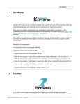
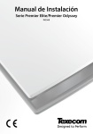
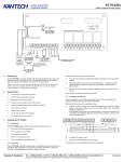
THANK YOU FOR VOTING TEXECOM
INSTALLATION MANUAL
Relay Module
Contents
Premier Relay Module Installation Manual
Contents
1. Overview............................................................................................ 3
General ..................................................................................................................3
Features ........................................................................................................3
Relay Module PCB Layout ...................................................................................3
2. Installation ......................................................................................... 4
General ..................................................................................................................4
Plugging on the Relay Module .....................................................................4
Testing on the Relay Module ........................................................................4
Connecting Outputs .............................................................................................5
Connecting Inputs ................................................................................................5
3. Specifications.................................................................................... 6
Electrical ................................................................................................................6
Environmental .......................................................................................................6
Physical .................................................................................................................6
Standards ..............................................................................................................7
Warranty ................................................................................................................7
2
INS191
Premier Relay Module Installation Manual
Overview
1. Overview
General
The Premier RM8 Relay Module is compatible with any control panels that have a
plug on RedCARE/Dualcom footprint.
Features
•
8 relay outputs (12V, 3Amp each)
•
8 Auxiliary inputs (-ve applied)
•
Auxiliary 12V output (protected by a 1 Amp fuse)
•
Relay ON indication via LED’s
Relay Module PCB Layout
Auxiliary Inputs 1 - 8 (-ve applied)
F1
Relay ON
Indicators
LED1
LED2
LED3
LED4
LED5
LED6
LED7
1 Amp
Aux 12V
Fuse
LED8
1 Amp
RLY1
RLY2
RLY3
RLY4
RLY5
Relay Outputs 1 - 8
INS191
RLY6
RLY7
RLY8
Aux 12V
3
Installation
Premier Relay Module Installation Manual
2. Installation
General
Before attempting to install the Premier RM8 relay module, isolate ALL power from
the control panel (AC Mains and Battery). Do not continue if there is power still
present on the control panel.
!"
Plugging on the Relay Module with power still present on the control panel
may damage the relay module, control panel or both and invalidate any
warranty.
Plugging on the Relay Module
1.
Ensure that the Relay Module is the correct way up (see page 3).
2.
Ensure that all pins on the control panel line up the sockets on the Relay
Module.
3.
Gently press down on the Relay Module until the relay Module is seated
correctly.
4.
Reconnect power to the control panel.
Testing on the Relay Module
4
1.
For plug on operation, test the Relay Module in accordance with the
control panel instructions.
2.
To test the auxiliary inputs, apply 0V to each input in turn and ensure that
the correct LED illuminates and a click is heard from the relay.
INS191
Premier Relay Module Installation Manual
Specifications
Connecting Outputs
The Premier RM8 Relay Module has 8 outputs. These outputs can be used to drive
auxiliary devices such as LED’s, sounders or communicators etc. Each output is a
clean contact relay rated at 3A @ 12V. The diagram below shows typical wiring
examples for the outputs:
Premier Rm8 Relay Module
Connecting Inputs
The Premier RM8 Relay Module has 8 auxiliary inputs. These inputs can be used to
activate the relays from an external source. Each input is -Ve applied and draws up to
30mA. The diagram below shows typical wiring examples for the inputs:
1
3
-Ve Outputs
from external
5 Source Outputs
6
4
Premier Rm8 Relay Module
INS191
7
8
5
Specifications
Premier Relay Module Installation Manual
3. Specifications
Electrical
Operating Voltage
10 - 13.7VDC
Current Consumption
Quiescent
One Relay ON
ALL Relays On
10mA
40mA
250mA
Outputs
O/P 1 to 8
3A @ 12V, Clean Contact (each)
Inputs
O/P 1 to 8
30mA -ve applied (each)
Environmental
Operating Temperature
-10°C (+14°F) to +50°C (+122°F)
Storage Temperature
-20°C (-4°F) to +60°C (+140°F)
Maximum Humidity
95% non-condensing
EMC Environment
Residential
Commercial
Light Industrial
Industrial
Physical
Dimensions
145mm x 75mm x 30mm
Packed Weight
100g approx.
6
INS191
Premier Relay Module Installation Manual
Specifications
Standards
Conforms to European Union (EU) Electro-Magnetic Compatibility (EMC) Directive
89/336/EEC (amended by 92/31/EEC and 93/68/EEC).
The CE mark indicates that this product complies with the European requirements
for safety, health, environmental and customer protection.
Warranty
All Texecom products are designed for reliable, trouble-free operation. Quality is
carefully monitored by extensive computerised testing. As a result the Premier RM8
relay module is covered by a two-year warranty against defects in material or
workmanship.
As the Premier RM8 relay module is not a complete alarm system but only a part
thereof, Texecom cannot accept responsibility or liability for any damages
whatsoever based on a claim that the Premier RM8 failed to function correctly.
Due to our policy of continuous improvement Texecom reserve the right to change
specification without prior notice.
Premier is a trademark of Texecom Ltd.
INS191
7
Texecom Limited, Bradwood Court, St. Crispin Way, Haslingden, Lancashire
BB4 4PW, England.
Technical Support:
Tel: +44 (0)1706 234833
Tel: +44 (0)1706 234811
Fax: +44 (0)1706 213187
INS191