1
AN-628
For Windows NT Systems
a. From the Windows NT Control Panel, select the
Devices icon. The Devices dialog box appears.
• For dual supplies, connect JP15 and JP12 to connect
the –5V pin to VSS of U1 and U3.
Warning: Apply +2.5 V to Pin +5V and –2.5 V to
Pin –5V instead.
• Select the states of PR and WP from the DIP switches
on the evaluation board.
• SDO can be monitored at TPSDO.
Step 5—Applying the Power Supply
Provide a power supply to the ADN2850 evaluation
board according to Step 4 for a single supply or for
dual supplies.
Step 6—Using the Evaluation Board
To open the ADN2850 software program, from Windows
click Start → Programs → ADN2850 Rev G.
b. Select dlportio and click the Startup button. The
device Startup Type dialog box appears. From the
option buttons, select Automatic, and then click OK.
Figure 2 shows the graphical interface. In the Direct Control pane, on the right, you can move the scroll bars or
click the buttons to control the device. In the top pane,
you can adjust the bit pattern and then click Run to program the device. In the bottom pane, you can
approximate RWA and RWB by first entering the measured
RAB after power is applied.
Step 7—Measuring the Result
Use a multimeter to measure the result of your program
applications on the ADN2850 evaluation board.
UNINSTALLING SOFTWARE
To uninstall the ADN2850 software and NTPORT driver,
use Add/Remove Programs in the Control Panel.
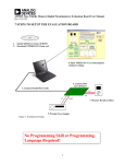
Step 3—Connecting the Parallel Port Cable
Connect the parallel port cable from LPT1 on your PC to
the ADN2850 evaluation board.
TECHNICAL SUPPORT
Due to the variations in computer platforms and configurations, Analog Devices, Inc., cannot guarantee the
software described in this application note to work on all
systems. If you encounter problems, send email to
[email protected] or call 1-408-382-3082 for
applications support. If you are interested in the
ADN2850 source code, send email to [email protected]
for more information.
Step 4—Configuring the Evaluation Board
Follow these requirements to configure the ADN2850
evaluation board:
• For a single supply, connect JP14 and JP13 to
ground V SS of U1 and U3. Apply 5 V to Pin +5V.
Note: Some boards do not come with jumper
caps. You should supply suitable caps or simply
short the jumpers for proper operation.
–4–
REV. 0