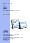
1
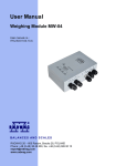
User manual
Weighing module MW-01
Manual number:
ITKU-29-04-03-12-A
BALANCES AND SCALES
RADWAG Wagi Elektroniczne, 26–600 Radom Bracka 28 Street - POLAND
Phone +48 48 38 48 800, phone/fax. +48 48 385 00 10
Selling department +48 48 366 80 06
www.radwag.com
MARCH 2012
2
CONTENT
1.
2.
3.
4.
APPLICATION ............................................................................................................................5
PRECAUTIONARY MEASURES................................................................................................5
WARRANTY CONDITIONS........................................................................................................5
TECHNICAL PARAMETERS .....................................................................................................6
4.1. INPUT/OUTPUT parameters ................................................................................................7
5. CONSTRUCTION .......................................................................................................................7
5.1. External view.........................................................................................................................8
5.2. Dimensions ...........................................................................................................................8
5.3. Diagrams of connection cables.............................................................................................9
6. INSTALLATION of “MwMANAGER” software.......................................................................11
6.1. Minimal hardware requirements..........................................................................................11
6.2. Installation procedure..........................................................................................................12
7. PC PROGRAM DESCRIPTION ................................................................................................15
7.1. Weighing window ................................................................................................................15
7.2. Application settings .............................................................................................................16
7.2.1. Connection settings...................................................................................................16
7.2.2. Language ..................................................................................................................18
7.2.3. Other .........................................................................................................................19
7.3. Parameters .........................................................................................................................19
7.3.1. User Parameters .......................................................................................................20
7.3.2. Communication settings ............................................................................................21
7.3.3. Functions I/O .............................................................................................................23
7.4. Functions ............................................................................................................................25
7.4.1. Dosing .......................................................................................................................25
7.4.2. Checkweighing ..........................................................................................................29
7.4.3. Input/output state.......................................................................................................30
8. WEIGHING................................................................................................................................31
8.1. Terms of use .......................................................................................................................31
8.2. Zeroing................................................................................................................................32
8.3. Tarring.................................................................................................................................33
8.4. Weighing on dual range scales...........................................................................................33
8.5. Toggling between weight units............................................................................................34
9. SCALE PARAMETERS ............................................................................................................35
9.1. Autozero function ................................................................................................................35
9.2. Median filter ........................................................................................................................36
9.3. Filter ....................................................................................................................................36
10. CHECKWEIGHING .................................................................................................................37
10.1. LO limit ..............................................................................................................................37
10.2. MIN/MAX limit ...................................................................................................................37
11. DOSING ..................................................................................................................................38
12. PARAMETERS IN FILE ..........................................................................................................39
12.1. Saving to file......................................................................................................................40
12.2. Uploading file data ............................................................................................................41
13. OFFLINE MODE .....................................................................................................................43
3
14. COMMUNICATION PROTOCOL............................................................................................44
14.1. General information ..........................................................................................................44
14.2. A set of commands ...........................................................................................................44
14.3. Respond message format .................................................................................................45
14.4. Command’s description ....................................................................................................45
14.4.1. Zeroing....................................................................................................................45
14.4.2. Tarring.....................................................................................................................46
14.4.3. Get tare value .........................................................................................................46
14.4.4. Set tare value..........................................................................................................46
14.4.5. Send the stable result in basic unit .........................................................................47
14.4.6. Send the result immediately in basic unit ...............................................................47
14.4.7. Send the stable result in current unit ......................................................................48
14.4.8. Send the result immediately in current unit.............................................................48
14.4.9. Switch on continuous transmission in basic unit.....................................................49
14.4.10. Switch off continuous transmission in basic unit...................................................49
14.4.11. Switch on continuous transmission in current unit ................................................49
14.4.12. Switch off continuous transmission in current unit ................................................50
14.4.13. Set lower threshold ...............................................................................................50
14.4.14. Set upper threshold...............................................................................................50
14.4.15. Read lower threshold ............................................................................................51
14.4.16. Read upper threshold ...........................................................................................51
14.4.17. Send all implemented commands.........................................................................51
15. COMUNICATION MODULE PROFIBUS ................................................................................52
15.1. General information ..........................................................................................................52
15.2. Setting instrument’s address in a Profibus network ..........................................................52
15.3. Memory map .....................................................................................................................53
15.3.1. Output address .......................................................................................................53
15.3.2. Input address ..........................................................................................................54
15.4. Description of variables.....................................................................................................54
15.4.1. Output variables......................................................................................................54
15.4.2. Input variables ........................................................................................................56
16. MODBUS COMMUNICATION PROTOCOL...........................................................................59
16.1. Basic information ..............................................................................................................59
16.2. Addressing a device in ModBus network ..........................................................................60
16.3. Register tables in ModBus network ..................................................................................60
16.3.1. Table of output registers .........................................................................................61
16.3.2. Table of input registers ...........................................................................................62
16.4. Software for controller PLC SIEMENS S7-300 .................................................................62
17. ERROR MESSAGES ..............................................................................................................63
4
1. APPLICATION
MW-01 weighing module is intended for constructing industrial load cell
scales. Depending on application, communication with the weighing module
can be carried out through the following interfaces: RS232, RS485, Ethernet,
Profibus or CAN. MW-01 is designed for cooperation with indicators series
PUE 5, PUE 7 or PC computers.
Operating of the weighing module MW-01 from a PC level is carried out with
a computer software “MwManager”. A detailed description of the application
is included in the further section of the MW-01 user manual.
2. PRECAUTIONARY MEASURES
A. Please, read carefully this user manual and use the device according
to its intended use;
B. Weighed loads should be placed possibly in the central setion of the
weighing platform;
C. The weighng platform should be loaded with objects which gross
weight does not exceed the maximal capacity of the scale;
D. Do not leave heavy loads on the weoghing patform for longer period
of time;
E. In case of failure, immediately disconnect the power supply;
F. Devices that are to be decommissioned should be utilized according
to valid legal regulations.
3. WARRANTY CONDITIONS
A. RADWAG is obliged to repair or change those elements that appear
to be faulty because of production and construction reason,
B. Defining defects of unclear origin and outlining methods of their
elimination can be carried out only in participation of the user and
the manufacturer representatives,
C. RADWAG does not take any responsibility connected with defecting
or loss deriving from unauthorized or inappropriate (not adequate
to manuals) production or service processes,
5
D. Warranty does not cover:
• Mechanical failures caused by inappropriate exploitation
of the device or failures of thermal or chemical origin or
• Defects caused by atmospheric discharge, overvoltage in mains
or other random event,
• Maintenance activities (cleaning of the weighing module).
E. Warranty loss appears if:
• A repair is carried out by an unauthorized service,
• Intrusion into mechanical or electronic construction
of unauthorized people,
• Removing or destroying protection stickers for the weighing module
F. The detailed warranty conditions are listed in the warranty certificate.
G. Contact with Authorized Service: +48 48 384 88 00 ext. 106 or 107.
4. TECHNICAL PARAMETERS
MODEL
MW-01 ver.1
MW-01 ver.2
Interface
RS232, RS485,
Ethernet
RS232, PROFIBUS,
Ethernet
Power Supply
8 ÷ 30VDC
Housing
IP rating
Working temperature
OIML class
Number of verification intervals
Max. increase of input signal
Min. voltage per verification division
Min. load cell impedance
Max. load cell impedance
metal
IP 66
-10°C ÷ 40°C
III
10 000
19,5mV
0,5µV
80Ω
1200Ω
Load cell excitation voltage
Load cell connectivity
Number of weighing platforms
2INE/3OUT
Transmission Speed RS232 RS485
5VDC
4 or 6 wire shielded cable
1
Standard
Default 57600 bit/s
6
4.1. INPUT/OUTPUT parameters
The module features 2 optoisolated inputs, 2 reed relay outputs
and fast transistorized output type open collector.
OUT1 – OUT2 Parameters
Number of outputs
Type of outputs
Conductor intersection
Maximum switchable current
Maximum conducted voltage
2
Reed operating contact
0.14 – 0.5mm2
200mA
50VDC
Output OUT3 Parameters
Number of outputs
Type of outputs
Umax
Imax
1
Transistor
5VDC
100mA
Input Parameters
Number of inputs
Type of inputs
Conductor intersection
Control voltage range
2
Optocoupled
0.14 – 0.5mm2
5 -24V DC
5. CONSTRUCTION
MW-01 weighing module features metal housing. The signal conductors are
let out through glands. MW-01 communicates with external devices through
one of accessible interfaces: RS485, RS232, Ethernet, Profibus or CAN.
The weighing module enables cooperation with indicators or PC computers.
It features 2 optoisolated inputs, 2 reed relay outputs and one fast transistor
output. The weighing module is supplied form 8÷30VDC.
7
5.1. External view
Fig.1 Weighing module MW-01
5.2. Dimensions
Fig.2 Dimensions of the MW-01
8
5.3. Diagrams of connection cables
RS232 cable
Fig. 3 PT0145 Cable
RS485 cable
Fig. 4 PT0012 Cable
9
Ethernet cable
Fig. 5 PT0014 Cable
IN/OUT cable
Fig. 6 PT0146 Cable
Power cable
Fig. 7 PT0147 Cable
10
6. INSTALLATION of “MwMANAGER” software
Caution:
• In order to install the program on the computer with older version
“MwManager” softwre, uninstall the previous version first,
• The installation instruction was made for Windows 7 and it is
compatibile with former versions of MS Windows
• Proper operation of the program reguires installing Microsoft .NET
Framework ver. 2.0 or higher. It is accessible on Microsoft website:
http://www.microsoft.com/downloads/details.aspx?displaylang=pl&
FamilyID=0856eacb-4362-4b0d-8edd-aab15c5e04f5
• Proper operation of the program reguires installing all accessible
ServicePacks for your operating system.
• Due to continuous software updates there may occur some
discrepancies between the instruction and the program,
• RADWAG takes no responsibility for the consequences of the
software operation, and any errors resulting from the incorrect
software operation,
• RADWAG takes no responsibility for loss or protection of any data
caused by the incorrect utilization of the software or computer.
6.1. Minimal hardware requirements
Proper operation of the software requires a computer with below specified
configuration:
• A PC computer with installed OS MS Windows 2000/XP/2003/Vista/7,
• processor 2.4 GHz or faster,
• RAM 512 MB or more (recommended 1 GB),
• At least 1 GB of free space on the hard drive,
• Display with minimum resolution 800 x 600,
• DVD drive.
11
6.2. Installation procedure
1. On receiving an installation file of MwManager x.x.x.x.exe software,
run installation file, select language version and press OK key.
2. Press
in the welcome window:
3. Browse window:
12
If necessary, change the software insallation folder, and press
.
4. Window for selecting tasks:
On marking / unmarking available option, press
13
key.
5. Installation window:
In order to install the software, press „Install” key.
6. Software installation completion window:
To finish installation process, press „Finish” key.
14
7. A shortcut will be created on computer’s desktop.
7. PC PROGRAM DESCRIPTION
Operation of the weighing module from PC computer level requires
application ”MwManager”. The application can operate in MS Windows
environment with installed add-on .NET framework 2.0. The program
enables calibrationg the module, displaying current mass indication, tarring,
zeroing, setting filters and functions for corresponding inputs and outputs.
Caution:
1. This manual complies with the software “MwManager” starting from
version 1.0.2.1 and weighing module program Prj215 from version 2.2.
2. The entered values are accepted by pressing Enter key. The changes
are saved in the weighing module on pressing Save key. All temporary
parameters settings that are not saved in the weighing module are
highlighte in red.
7.1. Weighing window
Fig.8 View of the software’s weighing window
On completing initializating procedure, the weighing window displays below
pictograms:
- precise zero indication
- stable measurement result
- weighing unit
- weighing platform number
15
If the indication is other than zero – press the zeroing key.
Function keys:
-
Zeroing
-
Taring
7.2. Application settings
comprises the settings for conneting the weighing
Tab
module, choosing interface language version and other software options.
7.2.1. Connection settings
,
key opens a window for establishing
In tab
connection with the weighing module.
Fig.9 Connection settings’ window
16
Description:
Means of connection
Interface for connecting to the weighing module
RS 232
Connection via port RS232
TCP/IP
Ethernet connection
RS 485
RS 485 connection
Offline
The offline mode is used for saving and editing all
indispensable parameters of the configuration file.
RS232:
Port
Choosing a COM port number to which the weighing
module is plugged
Baud rate
Baud rate for the RS232 interface. 57600 bps by default
Parity
Parity bit parameter. “None” by default
Data bits
Number of data bits. 8 by default
Stop bits
Number of stop bits. 1 by default
TCP/IP:
Adres IP
IP address of the device, default setting 192.168.0.2
Port
Port set in the weight module, default setting 4001.
RS485:
Port
Choosing a COM port number to which the weighing module is plugged
Baud rate
Baud rate for the RS485 interface. 57600 bps by default
Address
Weighing module address in the net
Caution:
1. The default baud rate of RS232 and RS485 interfaces in the MW-01
is set to 57600 bps;
2. If case of problems with establishing a connection to the weighing
module, set and check accessible baud rates or connect through
Ehternet interface;
3. If the display is set to port RS232, then connecting the computer software
through the same port is impossible. Display operation on this port is
restored on restarting the module (unplugging and repeated plugging
to mains).
17
Keys description:
Disconnect
Communication disconnected
Reconnect
Switching off and on (communication restart) communication with the device
Connect
Establishing connection with the weighing module
7.2.2. Language
Use tab
, and
key to open a window enabling
changing the language of the software.
Fig.10 Language selection window
On selecting the language version, press “Apply” key to save the changes.
Accessible language versions:
•
•
•
•
•
•
Czech
English
French
German
Polish
Spanish
18
7.2.3. Other
Use tab
,
key to start other software options.
Fig.11 Other options window
Tick “autostart” option, so that on switching on the software automatically
connects to the weighing module, by the default of last activated means of
connection.
7.3. Parameters
comprises all factory and user parameters, and also the
Tab
communication parameters of the weighig module and functions of 2 inputs
and 3 outputs.
19
7.3.1. User Parameters
,
key to open a window with user parameters
Use tab
of the weoghing module. The parameters are visible and edittable for each
software user.
Fig.12 User parameters window
List of user parameters:
Autozeroing
-
tick to enable autozeroing
Beep
-
Sound signal
Median filter
-
tick to enable median filter
Filter
-
tick to enable averaging filter
Current unit
-
Toggling between weighing units in the weighing window
20
7.3.2. Communication settings
Use tab
,
key to open a window with communication
parameters of the weighing module and configuration of peripheral devices.
The parameters are visible and edittable to all software users, who establish
cmmunication with the weighing module.
•
Ethernet
Fig. 13 Communication parameters window for Ethernet
List of fields with description:
IP address
-
Device’s IP address, default 192.168.0.2
Subnet mask
-
Ethernet subnet mask, default 255.255.255.0
Default gate
-
Ethernet default gate, default 192.168.0.1
Port
-
TCP communication port, default 4001.
Timeout
-
Inactivity time in which the device breaks communication,
expressed in seconds, range 0 – 300 [s].
21
•
RS 232/485
Fig.14 RS 232/485 comunication parameters window
List of fields with description:
Module address
-
Weighuing module address in RS 485 network (the network
requires setting different address for each of the devices),
default set to 1. Available range from 1 to 254.
Baud rate RS232
-
Baud rate setting for RS 232 communication interface.
Default 57600 bps
Baud rate RS485
-
Baud rate setting for RS 485 communication interface.
Default 57600 bps
Caution:
Indicator series PUE7 and other devices may use the address for Ethernet
connection (TCP/IP) and connection through RS232. In such case, set
parameter „Module address” to default value 1 for MW-01 and in the
settings of PUE7.
On changing the communication parameters, save the settings and restart
the weighing module (by unplugging and repeated plugging to mains), so that
the inserted changes are effective. Remember, that the new parameters are
inserted in the connection settings window with the weighing module.
22
•
Devices / Interface
List of fields with description:
Additional
display port
-
Interface setting for the additional display for the communication
protocol of LCD display.
Modbus
-
Selecting Modbus protocol type and operating interface,
Offset adr.
Modbus
-
Offsetting memory addressing for Modbus protocol,
Default value 1 for correct operation of PLC controller.
Caution! In case of testing software ProfiModBusTester set the value
to 0. Available values 0 - 255.
7.3.3. Functions I/O
The weighing module features two inputs and three outputs.
,
key to open a window enabling software
Use tab
user to access configurating functions of the weighing module inputs and
outputs.
23
Fig.15 I/O configuration window
• Inputs’ configuration
Accessible input functions:
No
Input inactive
Tarring
Platform tarring
Zeroing
Platform zeroing
Start dosing
Initiate batching process
Stop dosing
Stop batching process
• Outputs’ configuration
Accessible output functions:
None
Output inactive
Stable
Signalling stable weighing result over LO limit
MIN stable
Signalling stable weighing result over LO limit but below MIN limit
MIN
Signalling unstable weighing result over LO limit but below MIN limit
OK stable
Signalling stable weighing result between MIN and MAX limits
OK
Signalling unstable weighing result between MIN and MAX limits
24
MAX stable
Signalling stable weighing result over MAX limit
MAX
Signalling unstable weighing result over MAX limit
Notice:
If a function is assigned to a specific output and the same output is used
for bulk or fine dosing then on batching start and continuation, the outputs
will be activated compatibly to the dosing parameters. End of dosing process
causes switching over the functions to outputs.
7.4. Functions
Use tab
to functions of dosing (batching), checkweighing, inputs
and outputs status and simulation.
7.4.1. Dosing
Use tab
process.
,
key to open a window enabling setup of dosing
Fig.16 Window of dosing parameters
25
• Bar graph
The dosing window features a graphic bar visualizing mass indication
within the weighing range of the weighing module
Ticking the additional option extends bar graph scaling to 120 %
of the maximum dosing limit. If the fine dosing threshold is disabled,
then the bar graph is scaled according to the bulk dosing criteria.
Fig.17 Bar graph scaling for bulk dosing limit
Fig.18 Bar graph scaling for bulk and fine dosing limits
Fig.19 Bar graph for low weight without scaling
26
Fig.20 The same bar graph with enabled scaling option
•
Dosing parameters
Fig.21 Window for setting dosing parameters
The dosing process can consist of one or two phases depending on the
needs.
List of fields with description:
Bulk dosing limit
Mass value for which the high state of selected
outputs is set in the first dosing phase,
Output No. for bulk dosing
Selection of output or outputs numbers assigned
to the first dosing phase,
Fine dosing limit
Mass value for which the high state of selected
outputs is set in the second dosing phase,
Output No. for fine dosing
Selection of output or outputs numbers assigned
to the second dosing phase,
27
Accessible outputs for specific dosing phase:
1
High state on the first reed relay output
2
High state on the second reed relay output
3
High state on the third transistor output
1&2
Activating the first and second reed relay output
1&3
Activating the first reed relay output and the third transistor output
2&3
Activating the second reed relay output and the third transistor output
1&2&3
High state for all outputs
-
Dosing switched off for specific limit
• Dosing status
The dosing status window displays the current
status of dosing process
Description:
Dosing status
Dosing process status:
DOSING – dosing in progress
DISCONTINUED – dosing terminated by pressing STOP key.
STOP – dosing stoppage,
COMPLETED – Dosing completed.
• Simulation of inputs’ operation
Inputs simulation enables simulating the operation of a function assigned
to a specific input. The first input corresponds to the upper key, and the
bottom key simulates operation of a function assigned to the second
input.
28
• Dosing simulation
The lower part of the window comprises keys for starting and stopping
dosing process independently on the functions assigned to the inputs.
They enable starting and stopping the dosing process.
7.4.2. Checkweighing
Start option
and press
enabling checkweighing setting.
key to open a window
Fig.22 Checkweighing settings window
List of fields with description:
LO limit
Output signals MIN, OK, MAX only if it is over (net) LO limit
Min limit
Net mass value below which the MIN limit is signalled, above OK
Max limit
Net mass value for which the OK limit is signalled, above MAX
29
Signalling function with limits:
MIN
OK
MAX
Caution:
The checkweighing signalization in the software is accessible on setting
the functions to outputs.
7.4.3. Input/output state
and press
key to open a window enabling
Start option
setting the input and output signalling and setting output status.
Fig.23 Window of inputs and outputs status
30
Software inputs and outputs are numbered according the weighing module
documentation.
Active input / output (high state)
Inactive input / output (low state)
The simulation of output operation is possible on pressing the output number
which is activated immediately, provided there is no function assigned to the
output.
The simulation of inputs is accessible in the dosing window.
8. WEIGHING
Place weighed load on the weighing platform. As the stable measurement
is displayed, read the measurement result.
pictogram
8.1. Terms of use
In order to ensure a long lasting operation and correct measuring of weighed
loads it is advised to:
• Place the loads on the weighing platform gently and shocklessly:
• Place the loads in the centre of the weighing platform (eccentric
weighing errors are outlined in the norm PN-EN 45501 sections
3.5 and 3.6.2):
31
• Do not load the weighing platform with concentrated force:
• Avoid side loads and particularily side shocks:
8.2. Zeroing
In order to zero the mass indication in program „MwManager” press
key in the weighing window (the top right corner) or recall the zeroing
function. The display should indicate mass equal to zero and pictograms:
and
should be displayed.
Zeroing is equivalent to setting a new zero point comprehended by the
scale as a precise zero. Zeroing is possible only for stable display status.
Zeroing can be carried out by pressing the external push-button connected
to an input configured to zeroing function.
32
Caution:
Zeroing display status can only be carried out within the ±2% of the maximal
scale capacity. If a zeroed indication is beyond the range ±2% of maximal
scale indication, the display indicates error message Err2.
The procedure of defining inputs - keys is described in section 6.3.3
of this manual.
8.3. Tarring
In order to determine net weight place a container on the weighing platform
key or recall the tarring function.
and on indication staibilization press
The display should indicate mass equal to zero and pictograms: Net i
should be displayed.
While using tarring function pay attention not to exceed the maximal
measuring range of a scale. When taking the load and its packaging off the
weighing platform the display indicates value that is a sum of tarred weigts
preceded by minus sign.
Tarring can be carried out by pressing the external push-button connected
to an input configured to tarring function
Caution:
Tarring cannot be carried out if the scale display indicates zero or negative
values. In such case the display indicates error message Err3.
The procedure of defining inputs - keys is described in section 6.3.3
of this manual.
8.4. Weighing on dual range scales
Switching between the 1st range and the 2nd range takes place automatically,
without operator’s interference, at the point of reaching the Max of the 1st
range.
Weighing in range II is signalled by displaying pictogram
in the top left
corner of the display. When unloading the weighing platform, the indication
returns to zero. Weighing in the 2nd range continuous until the indication
returns to AUTOZERO zone.
33
Fig. 24 Weighing window in the 2nd range
When in AUTOZERO zone, the indication retirns to precise zero, which is
and pictogram of the 2nd range
disappears
signalled by pictogram
from the display. Weighing returns automatically to the 1st range.
8.5. Toggling between weight units
The weight unit can be changes in the main window of “MwManager”
software by pressing
key.
Fig. 25 The main window with changed weighing unit
Selection options:
• If the basic weighing unit [kg], the following units are accessible:
[kg, lb, oz, ct, N, g]. For verifies scales, [lb, oz, N] are not accessible;
• If the basic weighing unit is [g], the following units are accessible:
[g, kg, lb, oz, ct, N] For verifies scales, [lb, oz, N] are not accessible.
34
9. SCALE PARAMETERS
Users can adjust the scale to ambient conditions (filtering level) or user
needs (autozero operation) and also determine the minimum weight limit
for operation of some basic scale functions.
>
The parameters are accessible in tab
.
List of scale parameters:
•
•
•
Autozero
Median Filter
Filter
9.1. Autozero function
In order to ensure precise scale indications the software “AUTOZERO”
function has been introduced. It is designed to automatically control and
correct scale’s zero indication.
When autozero function is enabled, the subsequent results are compared in
constant time intervals. If two subsequent results differ less than the declared
AUTOZERO range the scale automatically sets new zero point and
and zero state –
are displayed.
pictograms of stability –
If AUTOZERO is enabled, then each measurement always starts from the
precise zero point. There are, however, cases in which the function may
disturb measuring process. It is for instance while very slow loading the
weighing platform (for instsance pouring a load). In such case the zero
correcting set can correct the actual indication of load placed on the
scale’s weighing platform.
Procedure:
key,
• Enter the User parameters window by pressing
choose parameter <Autozeroing> and set the appropriate value.
35
Accessible settings:
NO
YES
-
autozero disabled
autozero enabled
9.2. Median filter
The intended use of the median filtering is eliminating shortlasting
interference of impulse character (e.g. mechanical shocks).
Procedure:
key, choose
• Enter User parameters window by pressing
parameter <Median Filter> and set its appropriate value.
Accessible settings:
None - median filter disabled
0.5, 1, 1.5, 2, 2.5 - median filter enabled
9.3. Filter
The intended use of the averaging filter is adjustment to existing ambient
conditions.
Procedure:
• Enter User parameters by pressing
<Filter> and set its appropriate value.
key, choose parameter
Accessible settings:
No, Very Fast, Fast, Average, Slow
Caution:
The higher filtering level the longer stabilization time of measurement
result.
36
10. CHECKWEIGHING
Checkweighing is a function that aims at precise weighing
a sample with pre-defined low anf high weighing limits
(checkweighing thresholds (LO – sample mass too low,
HI – sample mass too high, OK – sample mass correct).
Such software solution is a very good means for quick mass value evaluation
with no need for contiinuous monitoring the measurement result. The above
mentioned weighing status (LO, OK, HI) have their graphic visualization
presented on scale’s display.
The status is also indicated by optical signalization or controlled by the set
of external devices.
>0<
Lo
MIN
Min thres.
Max thres. MAX
OK
HI
Fig. 26 Illustration of intervals for checkweighing function
Caution:
The checkweighing configuration is described in section 7.4.2 of this manual.
10.1. LO limit
Parameter <LO limit> determines the net weight indicated on the display
which activates opertaion of outputs for status MIN, OK, MAX.
Procedure:
• Enter parameter <LO limit>, insert the value of LO limit and press
key.
Enter key. Save changes using
10.2. MIN/MAX limit
Parameter <MIN limit> in checkweighing determines the net weight limit
for which the checkweighing status is switched between MIN and OK.
Parameter <MAX limit > in checkweighing determines the net weight limit
for which the checkweighing status is switched between OK and MAX.
37
Output signalization is activated over the set net value of LO LIMIT.
Procedure:
• Enter parameter <MIN threshold> or <MAX threshold>, insert the limit
value and press Enter key. Save changes using
key.
11. DOSING
Dosing is a function enabling precise load measurement
to a pre-defined target value.
Parameter <Bulk dosing limit> determines in fast (bulk) dosing
the value of net mass for which one or a few outputs
are activated.
Parameter <Fine dosing limit> determines in slow (fine) dosing the value
of net mass for which one or a few outputs are activated.
Procedure:
• Enter parameter <Bulk dosing limit> or <Fine dosing limit>, insert
the limit value and press Enter key. Save changes using
key.
• Changes are confirmed by a message box:
• If any changes in limits values are introduced and but not saved, then
it is possible to preview the currently set limits by pressing
key.
• The readout is confirmed by a message box:
38
Caution:
The dosing function and its parameters are described in section 7.4.1
of this manual.
12. PARAMETERS IN FILE
“MwManager” software features saving set parameters in a file format
*.sav. The function can be utilized for saving weighing module settings
in a backup copy, which is restorable in case of module defect or further
utilization of the parameters while configuring larger number of weighing
modules.
Fig.27 An instance of a windpw with accessible option for saving and uploading a file
39
File format:
MW01_(factory number)_YY-MM-DD_HH-MM.sav
12.1. Saving to file
Procedure:
•
As the weighing module parameters are set, press
key to save them in a file.
•
Then, using system operation window browse for file saving directory,
and press
key.
Fig.28 System window “Save as”
Default saving directory: C:\Program Files\RADWAG\MwManager\Save\
•
Correctly saved parameters cause displaying the below message box:
40
Caution:
The system window look depends on installed OS version, and may differ
fro mthe one visible in Fig.28.
12.2. Uploading file data
Procedure:
•
In order to upload parameters from a file, press
•
Then, using system dialogue window, see fig. 29, select an earlier
saved file, and press
key
Fig.29 System window „Open”
41
key,
•
Next, using window for uploading groups of parameters select one
or all parameters to be uploaded to the weighing module.
Fig.30 Window for selecting groups of parameters
The selected parameters are grouped according to their location
in the main software menu.
•
Parameters that are correctly uploaded are confirmed by the below
message box:
42
13. OFFLINE MODE
The Offline mode enables starting different software options with no need to
connect to a weighing module. This mode of connection is created to enable
saving parameters without phsycial connecting to a weighing device.
Fig. 31. Window for starting Offline mode.
Procedure:
•
On software start, enter connection settings tab and in the connection
settings options select Offline, and press
key,
•
The weighing window displays a communicate as presented in Fig. 31,
•
Set parameters and save them into a file according to description in
section 12.1 of this manual.
43
14. COMMUNICATION PROTOCOL
14.1. General information
A. Serial communication protocol “weighing module – terminal”
is designed for establishing communication between a MW-01
weighing module and a peripheral device through interfaces:
RS232, RS485, Ethernet;
B. The protocol consists of commands sent from a peripheral
device to the weighing module, and responses sent inversely;
C. The responses are sent from the weighing module on each receipt
of a command. Each response is a reaction for a specific command;
D. Commands which form serial communication protocol enable checking
device’s status, and trigger its reaction, e.g. obtaining measurement
result from the weighing module, preview mass displaying window, etc.
14.2. A set of commands
Commands
Description of commands
Z
T
OT
UT
S
SI
SU
SUI
C1
C0
CU1
CU0
DH
UH
ODH
OUH
PC
Zeroing
Tarring
Get tare value
Set tare value
Send the stable result in basic unit
Send the result immediately in basic unit
Send the stable result in current unit
Send the result immediately in current unit
Switch on continuous transmission in basic unit
Switch off continuous transmission in basic unit
Switch on continuous transmission in current unit
Switch off continuous transmission in current unit
Set lower threshold
Set upper threshold
Read lower threshold
Read upper threshold
Send all implemented commands
44
Notice:
1. Each command have to be terminated in CR LF;
2. The best Policy for communication is not sending another
command until the former answer has been received.
14.3. Respond message format
After sending a request message you can receive:
XX_A CR LF
command accepted and in progress
XX_D CR LF
command completed (appears only after XX_A)
XX_I CR LF
command comprehended but cannot be executed
XX _ ^ CR LF
command comprehended but time overflow error appeared
XX _ v CR LF
command comprehended but the indication below the
XX _ OK CR LF
Command done
ES_CR LF
Command not comprehended
XX _ E CR LF
error while executing command – time limit for stable result
exceeded (limit time is a descriptive parameter of the scale)
XX
_
- command name
- substitutes spaces
14.4. Command’s description
14.4.1. Zeroing
Syntax Z CR LF
Possible answers:
Z_A CR LF
Z_D CR LF
- command accepted and in progress
- command completed
Z_A CR LF
Z_^ CR LF
- command accepted and in progress
- command comprehended but zero range overflow appeared
Z_A CR LF
Z_E CR LF
- command accepted and in progress
- time limit for stable result exceeded
Z_I CR LF
- command comprehended but cannot be executed
45
14.4.2. Tarring
Syntax: T CR LF
Possible answers:
T_A CR LF
T_D CR LF
- command accepted and in progress
- command completed
T_A CR LF
T_v CR LF
- command accepted and in progress
- command comprehended but tare range overflow appeared
T_A CR LF
T_E CR LF
- command accepted and in progress
- time limit for stable result exceeded
T_I CR LF
- command comprehended but cannot be executed
14.4.3. Get tare value
Syntax: OT CR LF
Reply: OT_TARA CR LF – command executed
Frame format:
1
2
3
4-12
13
O
T
space
tare
space
Tare
Unit
-
14
15
16
unit
17
18
19
space
CR
LF
9 characters justified to the right
3 characters justified to the left
Notice:
Tare values are always send in calibration unit.
14.4.4. Set tare value
Syntax: UT_TARE CR LF, where TARE – tare value
Possible replies:
UT_OK CR LF
- command completed
UT_I CR LF
- command correct, but not accessible at the moment
ES CR LF
- command incorrect (e.g. incorrect tare format)
46
Notice:
Use dots as decimal points in tare values.
14.4.5. Send the stable result in basic unit
Syntax: S CR LF
Possible answers:
S_A CR LF
S_E CR LF
- command accepted and in progress
- time limit for stable result exceeded
S_I CR LF
- command comprehended but cannot be executed
S_A CR LF
MASS FRAME
- command accepted and in progress
- mass value in basic unit is returned
Frame format:
1
2-3
4
5
6
7-15
16
S
space
stability
space
sign
mass
space
17
18
19
unit
20
21
CR
LF
Example:
S CR LF – computer command
S _ A CR LF - command accepted and in progress
S _ _ _ _ - _ _ _ _ _ _ 8 . 5 _ g _ _ CR LF – command done, mass value
in basic unit is returned.
14.4.6. Send the result immediately in basic unit
Syntax: SI CR LF
Possible answers:
SI_I CR LF
- command comprehended but cannot be executed at the moment
MASS FRAME
- mass value in basic unit is returned
Frame format:
1
2
3
4
5
6
7-15
16
S
I
space
stability
space
sign
mass
space
47
17
18
unit
19
20
21
CR
LF
Example:
S I CR LF – computer command
S I _ ? _ _ _ _ _ _ _ 1 8 . 5 _ k g _ CR LF - command done, mass value
in basic unit is returned immediately.
14.4.7. Send the stable result in current unit
Syntax: SU CR LF
Possible answers:
SU_A CR LF
SU_E CR LF
- command accepted and in progress
- timeout while waiting for stable results
SU_I CR LF
- command comprehended but cannot be executed
SU_A CR LF
MASS FRAME
- command accepted and in progress
- mass value in current unit is returned
Frame format:
1
2
3
4
5
6
7-15
16
S
U
space
stability
space
sign
mass
space
17
18
unit
19
20
21
CR
LF
Example:
S U CR LF – computer command
S U _ A CR LF - command accepted and in progress
S U _ _ _ - _ _ 1 7 2 . 1 3 5 _ N _ _ CR LF - command done, mass value
in current unit is returned.
14.4.8. Send the result immediately in current unit
Syntax: SUI CR LF
Possible answers:
SUI_I CR LF
- command comprehended but cannot be executed
MASS FRAME
- mass value in current unit is returned immediately
48
Frame format:
1
2
3
4
5
6
7-15
16
S
U
I
stability
space
sign
mass
space
17
18
19
unit
20
21
CR
LF
Example:
S U I CR LF – computer command
S U I ? _ - _ _ _ 5 8 . 2 3 7 _ k g _ CR LF - command executed and mass
returned
14.4.9. Switch on continuous transmission in basic unit
Syntax: C1 CR LF
Possible answers:
C1_I CR LF
- command comprehended but cannot be executed
C1_A CR LF
MASS FRAME
- command comprehended and in progress
- mass value in basic unit is returned
Frame format:
1
2
3
4
5
6
7-15
16
S
I
space
stability
space
sign
mass
space
17
18
unit
14.4.10. Switch off continuous transmission in basic unit
Syntax: C0 CR LF
Possible answers:
C0_I CR LF
- command comprehended but cannot be executed
C0_A CR LF
- command comprehended and executed
14.4.11. Switch on continuous transmission in current unit
Syntax: CU1 CR LF
49
19
20
21
CR
LF
Possible answers:
CU1_I CR LF
- command comprehended but cannot be executed
CU1_A CR LF
MASS FRAME
- command comprehended and in progress
- mass value in current unit is returned
Frame format:
1
2
3
4
5
6
7-15
16
S
U
I
stability
space
sign
mass
space
17
18
19
unit
14.4.12. Switch off continuous transmission in current unit
Syntax: CU0 CR LF
Possible answers:
CU0_I CR LF
- command comprehended but cannot be executed
CU0_A CR LF
- command comprehended and executed
14.4.13. Set lower threshold
Syntax: DH_XXXXX CR LF, where: XXXXX – mass format
Possible answers:
DH_OK CR LF
- command executed
ES CR LF
- command not comprehended (wrong mass format)
14.4.14. Set upper threshold
Syntax:
UH_XXXXX CR LF, where: XXXXX – mass format
Possible answers:
UH_OK CR LF
- command executed
ES CR LF
- command not comprehended (wrong mass format)
50
20
21
CR
LF
14.4.15. Read lower threshold
Syntax: ODH CR LF
Possible answers: DH_MASA CR LF - command executed
Frame format:
1
2
3
4-12
13
D
H
space
mass
space
Mass
Unit
14
15
16
unit
17
18
19
space
CR
LF
17
18
19
space
CR
LF
- 9 characters justified to the right
- 3 characters justified to the left
14.4.16. Read upper threshold
Syntax: OUH CR LF
Possible answers: UH_MASA CR LF - command executed
Frame format:
1
2
3
4-12
13
U
H
space
mass
space
Mass
Unit
14
15
16
unit
- 9 characters justified to the right
- 3 characters justified to the left
14.4.17. Send all implemented commands
Syntax: PC CR LF
Possible answers:
PC_A_”Z,T,S,SI,SIA,SU,SUI,C1,C0,CU1,CU0,DH,ODH,UH,OUH,OT,UT,
PC" – command executed, the weighing module has sent all the implemented
commands.
51
15. COMUNICATION MODULE PROFIBUS
15.1. General information
Communication module Profibus ensures exchanging data between
a superordinate controlling unit (master) and a weighing module MW-01
(slave) in accordance with protocol Profibus DP.
The superordinate unit (master):
•
•
cyclically reads inputs signals fro mthe weighing module MW-01,
cyclically saves outputs status to the weighing module MW-01.
Functions of Profibus communication with the weighing module MW-01:
•
•
•
•
•
•
•
•
•
•
•
•
•
•
•
Mass readout from the weighing module
Tarring the weighing module
Zeroing the weighing module
Reading module’s status
Reading current measuring unit
Setting and reading tare value
Setting and reading LO threshold value
START / STOP of dosing process
Setting and reading the value of bulk (fast) dosing threshold
Setting and reading the value of fine (slow) dosing threshold
Setting outputs status
Reading the status of dosing process
Reading inputs status
Setting and reading Min threshold value
Setting and reading Max threshold value
15.2. Setting instrument’s address in a Profibus network
The address of the weighing module MW-01 in Profibus network has to be
set in accordance with module addressing specification. (See point 7.3.2
of this user manual – „Communication settings”). Field module address
is used to set corresponding address of the device in Profibus network.
52
15.3. Memory map
15.3.1. Output address
Address
0
1
2
3
4
5
6
7
8
9
Offset
0
M
M
M
M
T
T
T
T
J
J
1
S
S
LO
LO
LO
LO
-
-
-
-
2
-
-
-
-
-
-
-
-
-
-
3
-
-
-
-
-
-
-
-
-
-
4
-
-
-
-
-
-
-
-
-
-
5
-
-
-
-
-
-
-
-
-
-
6
-
-
-
-
ST
ST
SW
SW
MIN
MIN
7
MIN
MIN
MAX
MAX
MAX
MAX
DS
DS
DS
DS
8
DW
DW
DW
DW
-
-
-
-
-
-
9
-
-
-
-
-
-
-
-
-
-
Table. 1
M
T
J
S
LO
ST
SW
MIN
MAX
DS
DW
- Mass for a platform, 4 bytes, float
- Tare for a platform, 4 bytes, float
- Current measuring unit of a platform, 2 bytes, word
- Platform status, 2 bytes, word
- Lo threshold of a platform, 4 bytes, float
- Process status, 2 bytes, word
- Inputs status, 2 bytes, word
- MIN threshold, 4 bytes, float
- MAX threshold, 4 bytes, float
- Bulk (fast) dosing threshold, 4 bytes, float
- Fine (slow) dosing threshold, 4 bytes, float
53
15.3.2. Input address
Address
0
1
2
3
4
5
6
7
8
9
C
C
CP
CP
-
-
T
T
T
T
1
LO
LO
LO
LO
SW
SW
MIN
MIN
MIN
MIN
2
MAX
MAX
MAX
MAX
DS
DS
DS
DS
DW
DW
3
DW
DW
-
-
-
-
-
-
-
-
4
-
-
-
-
-
-
-
-
-
-
Offset
0
Table. 2
C
CP
T
LO
SW
MIN
MAX
DS
DW
- command, 2 bytes, word
- command with a parameter, 2 bytes, word
- Tare for a platform, 4 bytes, float
- Lo threshold of a platform, 4 bytes, float
- Outputs status, 2 bytes, word
- MIN threshold, 4 bytes, float
- MAX threshold, 4 bytes, float
- Bulk (fast) dosing threshold, 4 bytes, float
- Fine (slow) dosing threshold, 4 bytes, float
15.4. Description of variables
15.4.1. Output variables
Readout of output variables enables obtaining data on instrument’s status.
Notice:
All output values, except for mass, are displayed in adjustment/calibration
unit.
Name of output variable
mass
tare
unit
status
address
length [word]
0
4
8
10
2
2
1
1
54
data type
float
float
word
word
LO
process status
input status
MIN
MAX
bulk (fast) dosing threshold
fine (slow) dosing threshold
12
64
66
68
72
76
80
2
1
1
2
2
2
2
float
word
word
float
float
float
float
Table. 3
• mass – mass value in current unit is returned,
• tare – tare value in calibration/adjustment unit is returned,
• unit – determines current (displayed) measuring unit:
Byte no.
Unit
g
kg
ct
lb
oz
N
B5
B4
B3
B2
B1
B0
Dec
0
0
0
0
0
1
0
0
0
0
1
0
0
0
0
1
0
0
0
0
1
0
0
0
1
0
0
0
0
0
0
1
0
0
0
0
1
2
4
8
16
32
gram
kilogram
carat
pound
ounce
Newton
• status – determines scale’s status
Status
bytes
0
1
2
3
4
5
6
7
8
Task
Dec
correct measurement (no error message from scale)
stable measurement
scale in zero indication
scale tarred
scale in second measuring range
scale in third measuring range
scale reports NULL error
scale reports LH error
scale reports FULL error
1
2
4
8
16
32
64
128
256
For instance:
byte no.
value
B8
B7
B6
B5
B4
B3
B2
B1
B0
0
0
0
0
1
0
0
1
1
55
The scale does not report an error, the measurement is stable
in the second measuring range.
• LO – the value of LO threshold in calibration/adjustment unit is returned.
• Process status – determines the status of dosing process
Decimal value of
a variable (Dec)
byte no.
process status
process disabled (inactive)
dosing start
dosing stop
end of dosing process
0
1
2
3
B1
B0
0
0
1
1
0
1
0
1
• Inputs status – determines the status of inputs in a weighing module
MW-01:
input status
byte no.
In2
In1
B1
B0
Decimal value of
a variable (Dec)
OFF
OFF
ON
ON
OFF
ON
OFF
ON
0
0
1
1
0
1
0
1
0
1
2
3
• MIN – set value of MIN Threshold (in calibration/adjustment unit)
is returned.
• MAX – set value of MAX Threshold (in calibration/adjustment unit)
is returned.
• Bulk (fast) dosing threshold – set value of bulk (fast) dosing
threshold (in calibration/adjustment unit) is returned.
• Bulk (slow) dosing threshold – set value if fine (slow) dosing
threshold (in calibration/adjustment unit) is returned.
15.4.2. Input variables
Saving the input variables into the weighing module MW-01 enables
controlling module’s operation.
56
Notice:
All input values are set in reation to calibration/adjustment unit.
Name of input variable
address
length [word]
data type
command
0
1
word
complex command
2
1
word
tare
6
2
float
LO
10
2
float
output status
14
1
word
MIN
16
2
float
MAX
20
2
float
bulk (fast) dosing threshold
24
2
float
fine (slow) dosing threshold
28
2
float
Complex command parameters
Table. 4
• command – basic command. Setting of an appropriate command’s
byte is directly responsible for carrying out a task, in accordance with
below table:
command
bytes
0
task
Dec
scale zeroing
1
1
scale tarring
2
5
dosing process start
32
6
dosing process stop
64
For instance:
0000 0000 0010 0000 – command carried out, dosing process start
• complex command - Setting of an appropriate command’s byte
is directly responsible for carrying out a task, in accordance with
below table:
57
command
task
bytes
0
1
2
3
4
5
6
Dec
setting tare value
setting LO threshold value
setting outputs status
setting MIN threshold value
setting MAX threshold value
setting the value of bulk (fast) dosing threshold
setting the value of fine (slow) dosing threshold
1
2
4
8
16
32
64
For instance:
0000 0000 0000 0010 – command carried out, LO threshold set
to value given in LO parameter (address 10); See Table 4.
Notice:
A complex command requires setting an appropriate address
parameter from 6 to 28. See Table.4.
• tare – complex command parameter – tare value (in calibration /
adjustment unit).
• LO – complex command parameter – LO threshold value (in calibration
/ adjustment unit).
• outputs status – complex command parameter determining outputs
status of the weighing module MW-01.
Output status
byte no.
Out3
Out2
Out1
B2
B1
B0
OFF
OFF
OFF
OFF
ON
ON
ON
ON
OFF
OFF
ON
ON
OFF
OFF
ON
ON
OFF
ON
OFF
ON
OFF
ON
OFF
ON
0
0
0
0
1
1
1
1
0
0
1
1
0
0
1
1
0
1
0
1
0
1
0
1
58
Dec
0
1
2
3
4
5
6
7
• MIN - complex command parameter – MIN threshold value
(in calibration / adjustment unit).
• MAX - complex command parameter – MAX threshold value
(in calibration / adjustment unit).
• bulk (fast) dosing threshold – complex command parameter – the
value of bulk (fast) dosing threshold (in calibration / adjustment unit).
• fine (slow) dosing threshold – complex command parameter – the
value of fine (slow) dosing threshold (in calibration / adjustment unit).
Notice:
A command or a command with parameter is executed once on detecting its
corresponding byte setting. Should a command with the same byte be reexecuted, the byte must be reseted.
For instance:
command
address 1
address 0
tarring
zeroing command bytes
tarring
0000 0000
0000 0000
0000 0000
0000 0010
0000 0000
0000 0010
16. MODBUS COMMUNICATION PROTOCOL
16.1. Basic information
The weighing module MW-01 enables complete operation of programmable
controllers (PLC), which communicate through Modbus protocol class 0. The
weighing module in a network using modbus standard operates as slave on
an accessible interfaces, RS485 or Ethernet. According to the standard,
Modbus class 0, the device uses two functions:
• Read multiple registers (fc 3), for cyclic readout of signals from the
weighing module,
• Write multiple registers (fc 16), for cyclic record of the weighing module
statuses.
59
The weighing module MW-01 can operate in one of three modes:
• RS484 - RTU (device interface RS485, frame RTU),
• TCP/IP - RTU (device interface Ethernet, frame RTU),
• TCP/IP - Open ModBus (device interface Ethernet, frame Open
Modbus).
The functionalitz of Modbus protocol is based on a scheme used in Profibus
protocol, as described in point 15.3 and 15.4 of this user manual.
Caution:
Modbus address offset in the module that cooperates with PLC controller is
set to value 1, i.e. deafult setting. In case of a weighing module cooperating
with a test computer software, set the value to 0.
16.2. Addressing a device in ModBus network
Address of the weighing module MW-01 in modbus netowrk has to be set in
accordance to module addressing specification. (see point 7.3.2 of this user
manual – „Communication settings”). Use tab RS232/485, field module
address to set address of a device appropriate for the Modbus network.
The default port of the Ethernet interface (TCP/IP) in Modbus network is
set to 502.
16.3. Register tables in ModBus network
Numbers on the output and input register tables are described below,
and they are compatible with the Offset of Modbus address set for value
0. In case of a value setting from 0 do 255, add the set value of Offset of
Modbus address to the output or input register number.
60
16.3.1. Table of output registers
The weighing module uses 42 addresses for function Read Holding
Registers as listed in below table.
address
Length
[words
Data
type
Mass
0
2
float
Tare
4
2
float
Unit
Status
8
10
1
1
word
word
Lo
12
2
float
N. A.
16
2
float
N. A.
20
2
float
N. A.
N. A.
24
26
1
1
word
word
N. A.
28
2
float
N. A.
32
2
float
N. A.
36
2
float
N. A.
N. A.
40
42
1
1
word
word
N. A.
44
2
float
N. A.
48
2
float
N. A.
52
2
float
N. A.
N. A.
56
58
1
1
word
word
N. A.
60
2
float
Process status (Stop, Start)
Inputs status
64
66
1
1
word
word
Low threshold value
68
2
float
High threshold value
72
2
float
Bulk (fast) dosing threshold value
76
2
float
Fine (slow) dosing threshold
value
80
2
float
Name of output variable
N. A. – Register inactive.
61
Read Holding
Registers
0
1
2
3
4
5
6
7
8
9
10
11
12
13
14
15
16
17
18
19
20
21
22
23
24
25
26
27
28
29
30
31
32
33
34
35
36
37
38
39
40
41
16.3.2. Table of input registers
The weighing module uses 16 addresses for function Write Multiple
Registers as listed in below table.
Name of input variable
address
Length
[word]
1
1
1
Data type
Command
Command with parameter
N. A.
0
2
4
word
word
word
tare
6
2
float
Lo
10
2
float
Outputs status
14
1
word
MIN
16
2
float
MAX
20
2
float
Bulk (fast) dosing threshold
24
2
float
Fine (slow) dosing threshold
28
2
float
Write Multipe
Registers
0
1
2
3
4
5
6
7
8
9
10
11
12
13
14
15
N. A. - Register inactive.
16.4. Software for controller PLC SIEMENS S7-300
Description of software Siemens S7-300.
The software enables communicating of the weighing module MW-01
with the Siemiens S7-300 controller through Open Modbus TCP protocol.
The software is designed for below hardware specification.
Unit CUP: S7-313 2DP (6ES7 313-6CE00-0AB0 /V1.0)
Communication processor: CP 343-1 (6GK7 343-1EX10-0XE0 / V2.0)
Minimum software requirements:
Programming environment: STEP 7 V5.4 + SP3
Additional libraries: SIEMENS OPEN MODBUS TCP
Description:
Exchanging data with a weighing module MW01 is carried out through
data block DB1 of the following structure.
62
Name
Type
Description
Data acquired from the MW01 weighing module when a flag is set to
Read_Write = FALSE
Mass
REAL
Mass from the weighing module
Tare
REAL
Tare value from the weighing module
Unit
WORD
Measuring unit from the weighing module
Status
WORD
Weighing status from the weighing module
LO
REAL
LO threshold the weighing module
Data saved to the MW01 weighing module when a flag is is set to
Read_Write = TRUE
CMD
WORD
Command without a parameter sent to the module
CMD_PARAM
WORD
Command with a parameter sent to the module
RESERVED
WORD
N/A
Tara1
REAL
Tare value for a command with a parameter
LO1
REAL
Value of LO threshold with a parameter
OutPutsState
WORD
Output status for a command with a parameter
MIN
REAL
Min value for for a command with a parameter
MAX
REAL
Max value for a command with a parameter
FastDosing
REAL
Value of bulk (fast) dosing threshold for a command with
a parameter
SlowDosing
REAL
Value of fine (slow) dosing threshold for a command with
a parameter
Read_Write
BOOL
Flag for switching between date readout and record
17. ERROR MESSAGES
Err2
-
Value beyond zero range
Err3
-
Value beyond tare range
Err8
-
Exceeded time of tarring / zeroing operation
NULL
-
Zero value from A/D converter
FULL
-
Measuring range exceeded
HI
-
LH
-
Display range exceeded
Start mass error, indication out of range
(from -5% to +15% of start mass)
63
BALANCES AND SCALES
RADWAG BALANCSES AND SCALES
POLAND, 26 – 600 Radom, Bracka 28
Phone: +48 48 38 48 800, fax. + 48 48 385 00 10
[email protected]
www.radwag.com
64