1
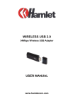
Wireless LAN PC Card
User’s Manual
Ver 1.4
Copyright © 2001 by manufacturer. All rights reserved.
No part of this documentation may be reproduced in any form or by any means or used to
make any derivative work (such as translation, transformation, or adaptation) without
written permission from the copyright owner.
All the other trademarks and registered trademarks are the property of their respective
owners.
Statement of Conditions
The content described in this manual may be improved or changed at any time and it is
subject to be changed without notice.
Manufacturer assumes no responsibility for errors contained herein or for direct, indirect,
special, incidental or consequential damages with the furnishing, performance, or use of
this manual or equipment supplied with it, even if manufacturer of its suppliers have been
advised of the possibility of such damages.
Electronic Emission Notices
This device complies with Part 15 of the FCC Rules. Operation is subject to the following
two conditions:
(1) This device may not cause harmful interference.
(2) This device will accept any interference received, including interference that may
cause undesired operation.
FCC Radio Frequency Interference Statement
This equipment has been tested and found to comply with the limits for a class B digital
device, pursuant to Part 15 of the FCC rules. These limits are designed to provide
reasonable protection against harmful interference when the equipment is operated in a
commercial environment. This equipment generates, uses, and can radiate radio frequency
energy and, if not installed and used in accordance with the instruction manual, may cause
harmful interference to radio communications. Operation of this equipment in a
residential area is likely to cause harmful interference in which case the user need to
correct the interference at his area. If the equipment causes interference to radio or
television reception, try to correct the interference by using one or more of the following
measures:
Ÿ Plug the equipment into an outlet that is on a different circuit from the television or
radio.
Ÿ Change the direction of the television or radio antenna until the interference
disappears.
Ÿ Move the equipment to one side or the other of the television or radio.
Ÿ Move the equipment farther away from the television or radio.
To assure continued compliance, any changes or modifications not expressly approved by
manufacturer could void the user’s authority to operate the equipment.
1
FCC Radiation Exposure Statement
This device and its antennas must operate with a separation distance of at least 5 cm from
all persons and must not be co-located or operating in conjunction with any other antenna
or transmitter. End users must be provided with specific operating instructions for
satisfying RF exposure compliance.
This product has been certified in France, Germany, Italy, Spain, Sweden, UK, and US.
2
LIMITED WARRANTY
This product is warranted by manufacturer to be free from defects in material and
workmanship for one (1) year from the date of purchase, unless otherwise stated.
During this period if this product is found to be defective in material or workmanship,
manufacturer or one of its authorized service facilities will at its option either repair or
replace this product without charge, subject to the following conditions, limitations and
exclusions:
1. This warranty extends to the original consumer purchaser only and is not
assignable or transferable.
2. This warranty shall not apply to any product which has been subjected to misuse,
abuse, abnormal use, negligence, alteration or accident, or has had its serial
number altered or removed.
3. This warranty does not apply to any defects or damage directly or indirectly
caused by or resulting from the use of unauthorized replacement parts and/or
service performed by unauthorized personnel.
4. This warranty does not apply to the software driver that accompanies this product.
This warranty is made expressly in lieu of all other warranties, expressed or implied,
including but not limited to any implied warranty of merchantability of fitness for a
particular purpose, and all other obligations on the part of Manufacturer provided,
however, that if the disclaimer of implied warranties is ineffective under applicable law,
the duration of any implied warranties arising by operation of law shall be limited to one
(1) year from the date of purchase or such longer period as may be required by applicable
law.
Manufacturer hereby disclaims any and all liabilities for consequential and incidental
damages arising out of or in connection with any breach of this warranty or any other
claim with respect to this product, including but not limited to claims of negligence, strict
liability in tort or breach of contract.
3
Table of Contents
1. INTRODUCTION ......................................................................................................................5
1.1 Features.................................................................................................................................5
1.2 Applications.........................................................................................................................5
1.3 Wireless LAN System.......................................................................................................6
1.3.1 802.11 Ad-Hoc Configuration ....................................................................................6
1.3.2 Infrastructure Configuration .......................................................................................6
2. INSTALLATION .......................................................................................................................9
2.1 Product Kit ...........................................................................................................................9
2.2 PC’s Minimum Requirements.........................................................................................9
2.3 Installing the Utility and Driver .....................................................................................9
2.3.1
2.3.2
2.3.3
2.3.4
Under MS Windows 95/98/Me/2000/XP ....................................................................9
Under MS Windows NT4.0 ......................................................................................10
Under MS Windows CE ...........................................................................................11
Under Linux ..............................................................................................................12
3. CONFIGURATION .................................................................................................................14
3.1 Under MS Windows 95/98/Me/NT/2000/XP ...........................................................14
3.2 Under MS Windows CE .................................................................................................20
4. SPECIFICATIONS ..................................................................................................................24
5. GLOSSARY...............................................................................................................................25
4
1. INTRODUCTION
Wireless LAN is local area networking without wires, which uses radio frequencies to
transmit and receive data between PC’s or other network devices. Wireless LAN is able to
configure independent networks and infrastructure networks. The former is suitable for
small or temporary peer-to-peer configurations, and the later is offering fully distributed
data connectivity via micro cells and roaming.
The WLAN PC Card is designed to meet the mobility, performance, security,
interoperability, management, and reliability requirements of IEEE 802.11b high data rate
standard. It is easy to install the WLAN PC Card on various devices with PCMCIA TYPE
II card slot. It is able to communicate with other IEEE 802.11b compatible products to
create a wireless LAN in your office or home.
1.1 Features
Ÿ Compliant with 11 Mbps 802.11b high-speed specification.
Ÿ Data rate 11/5.5/2/1 Mbps automatic fallback under noisy environment.
Ÿ Advanced Power Management for battery saving.
Ÿ Build PCB patch diversity antennas.
Ÿ Supports MS Windows 95/98/ME/NT/2000/XP/CE, and Linux.
Ÿ Interoperable with IEEE 802.11b compliant equipment.
Ÿ Supports full mobility and seamless roaming from cell to cell.
Ÿ Plug-and-play installation and easy client management with utility software
Ÿ Supports point-to-point and point-to-multipoint access.
Ÿ Direct Sequence Spread Spectrum (DSSS) technology provides robust,
interference-resistant and secure wireless connection.
Ÿ Wireless connection without the hassles and cost of cabling.
Ÿ Greater flexibility to locate or move networked PC’s.
1.2 Applications
Ÿ Home networking for device sharing - Remote access to corporate network
information email, file transfer and terminal emulation.
Ÿ Frequently changing environments - Retailers, manufacturers and banks that
frequently rearrange the workplace and change location.
Ÿ SOHO (Small Office and Home Office) users - SOHO users need easy and quick
installation of a small computer network functions.
Ÿ Inter-building connection - The wireless building-to-building network installs
quickly, requires no monthly lease fees, and provides the flexibility to reconfigure
easily.
Ÿ Typical applications include hard-to-wire buildings, campuses, hospitals/medical
offices, warehouse, security huts, exhibition centers, etc.
Ÿ Temporary LANs for special projects or occasions - Auditors require workgroups
at customer sites. Trade shows, exhibitions, retailers, airline, and shipping
companies need additional workstations for a peak period of data traffic.
5
1.3 Wireless LAN System
1.3.1 802.11 Ad-Hoc Configuration
An 802.11 Ad-Hoc wireless LAN is a group of computers, each equipped with one
WLAN PC Card, connected as an independent wireless LAN. Computers in a specific
802.11 Ad-Hoc wireless LAN must be configured at the same radio channel. 802.11
Ad-Hoc wireless LAN is applicable to a departmental scale for a branch or SOHO
operation.
Figure 1-1
802.11 Ad-Hoc Configuration
1.3.2 Infrastructure Configuration
An integrated wireless and wired LAN is called an infrastructure configuration. A group
of WLAN PC Cards and an Access Point (AP) is called a Basic Service Set (BSS). Each
WLAN PC Card in this BSS can be linked to any computer in the wired LAN
infrastructure via the AP.
Infrastructure configuration not only extends the accessibility of a WLAN PC Card to the
wired LAN, but also doubles the effective wireless transmission range between two
WLAN PC Cards.
BSS ID is, in essential, the ID of each independent WLAN PC Card. All WLAN PC
Cards configured without roaming options in this independent BSS must be configured
with BSS ID of that AP. You may need to check BSS ID of your AP by using its vendor
supplied program.
Infrastructure configuration is applicable to enterprise scale for wireless access to central
database, or wireless application for mobile workers.
Two APs can be used as a point-to-point link between two LANs. LAN interconnection is
applicable to a wireless backbone between buildings.
6
Figure 1-2
Infrastructure Configuration
The infrastructure configuration supports roaming capability for mobile workers. More
than one BSS can be jointly configured as an Extended Service Set (ESS). On account of
a continuous connection to the network, users within this ESS can roam freely. All
WLAN PC Cards and APs within one ESS must be configured with the same ESS ID.
Before setting up an ESS for roaming, it would be helpful to achieve good performance
by choosing a feasible radio channel and right places for APs.
7
Figure 1-3
Seamless Roaming
8
2. INSTALLATION
Use the procedures described in this chapter to install your WLAN PC Card under MS
Windows 95/98/Me/NT/2000 /XP/CE, and Linux.
2.1 Product Kit
Before starting installation, please make sure the WLAN PC Card package you purchased
includes the following items:
1) WLAN PC Card.
2) CD-ROM (including Driver/Utility and User’s Manual).
3) Quick Start Guide.
If anything is missing, please contact your vendor.
2.2 PC’s Minimum Requirements
To install the WLAN PC Card successfully, your PC (notebook, desktop, or PDA) should
meet the following minimum requirements:
1) A PCMCIA slot compliant with Release 2.1 of the PCMCIA specification.
2) Windows 95, 98, Me, NT, 2000, XP, CE or Linux operating system.
3) Minimum 10 Mbytes free disk space for installing the driver and the utility
program.
2.3 Installing the Utility and Driver
Depending on the operating system you use, please select one of the sections (2.3.1~2.3.4)
and follow the steps to install the Utility and Driver. Then go to Section 3 to continue the
procedure.
Note: Please do not plug your WLAN PC Card until the setup procedure has been
completed.
2.3.1 Under MS Windows 95/98/Me/2000/XP
Please follow the steps below to install the utility and driver.
1) Insert the supplied CD-ROM in the CD-ROM drive.
2) The InstallShield Wizard should start automatically. If Autorun is disabled in
your Windows settings, you will need to go to the Windows “Start” button,
choose “Run” and type “D:\setup.exe” in the text box, where D is the drive
letter of your CD-ROM drive.
3) Follow the InstallShield Wizard to install the driver and utility.
4) Reboot your PC after completing the installation process. (Recommended)
5) Plug your WLAN PC Card. The “Add New Hardware Wizard” automatically
loads the driver, then a new application (the Configuration & Monitor Utility)
icon will be displayed in the task bar.
6) Go to Section 3 for Configuration.
Note: In the MS Windows 2000/XP installation procedure, an extra window prompts you
to select the options whether you would like to install the “Digital Signature Not Found”
or not. You can safely select “YES”.
9
2.3.2 Under MS Windows NT4.0
What You Need to Know About MS Windows NT4.0
Although Windows NT 4.0 is similar in appearance with Windows 95/98/Me, and
Windows 2000, they have different philosophy when installing a new hardware.
Throughout this section it is assumed that you have the basic working knowledge of
Windows NT 4.0 and installing new network cards on this OS. Some specific features
of Windows NT 4.0 are briefly explained in this paragraph. Unlike Windows
95/98/Me, and Windows 2000, Windows NT 4.0 does not support the “Plug & Play”
and “Hot Swapping” features. In Windows NT 4.0 you need to inform the operating
system about the existence of the new card in order to start installing the driver. Also,
if you want to swap cards, you need to restart the PC to recognize the card.
Note: Being able to install the WLAN PC Card on to your PC running under Windows
NT 4.0, you will need to log on as “Administrator”. Also you will need to have at least
NT Service Pack 4 installed.
Installing the Utility
Please follow the steps below to install the utility.
1) Insert the supplied CD-ROM in the CD-ROM drive.
2) The InstallShield Wizard should start automatically. If Autorun is disabled in
your Windows settings, you will need to go to the Windows “Start” button,
choose “Run” and type “D:\setup.exe” in the text box, where D is the drive
letter of your CD-ROM drive.
3) Follow the InstallShield Wizard to install the utility.
4) Go to next step for installing the driver when completing the installation
process.
Installing the Driver
Since MS Windows NT4.0 does not support “Plug & Play”, you must enable the
detection of PC cards by the operating system in the following steps:
1) Click Start -> Settings -> Control Panel.
2) Double-click the “Devices” icon.
3) Select “PCMCIA” from the list and click the “Startup” button.
4) Set the Startup type to “Boot” and click “OK”.
5) Click “Close” on the “Devices” window, you must enable the Network support
By following the next steps to let the operating system know your new card.
1) Click Start -> Settings -> Control Panel.
2) Double-click the “Network” icon.
3) In the “Network Settings” window you will be prompted to install Windows
NT Networking if networking has not been installed yet. Click “Yes” and
follow the instruction on the screen. If networking has already been installed,
10
you will see a dialog with several tabs. Click the “Add” button in the
“Adapters” tab. Windows NT Networking Setup will determine the type of
network adapter card that you are going to use.
4) Locate and select the driver with the supplied CD-ROM to respond the prompt
of selecting a driver.
5) During the installation, a dialog box prompts for the I/O Base and IRQ
resource information. Go to Start -> Programs -> Administrative Tools ->
Windows NT Diagnostics -> select the “Resources” tab -> press the “IRQ”
button. Select one free IRQ from the list. Next, press the button “I/O Port” and
choose an 0x20 free I/O space. Add these values into the dialog box. If at any
point after the installation you want to change these values, go to the Control
Panel -> Network, select the Adapters tab, press the Properties button, and fill
in the new values.
6) Next Windows will start copying the files. If there is a version conflict, you
should normally keep the latest version between one or more of the files that
are being copied and the files in your system.
7) Restart your computer when completing the installation process.
Note: If the card is not working properly, make sure that your system has free resources
that show their availability after a restart procedure.
2.3.3 Under MS Windows CE
Please follow the steps below to install the utility and driver.
1) Insert the supplied CD-ROM in the CD-ROM drive.
2) Click “Start” button, choose “Run” and type “D:\wince\setup.exe” in the text
box, where D is the drive letter of your CD-ROM drive.
3) Follow the InstallShield Wizard to install the driver and utility.
4) Insert the WLAN PC card. When the PC card is installed after completing the
installation process. A window that has two WIN TCP/IP options will
automatically appear as shown in Figure 2-1.
11
Figure 2-1
A typical Screen with TCP/IP Options
5) Use the first option if you have plans to connect to an Access Point (become
associated) that is connected to a network, where a DHCP Server is available,
then an unique IP Address will be automatically assigned to your PC card.
Select the second option and assign an unique IP Address to your PC card in
any other case.
6) Go to Section 3 for Configuration.
2.3.4 Under Linux
Please follow the steps below to install the utility and driver.
1) Unpack the ATMEL_linux_drivers.tgz package (anywhere you like).
# tar xzvf ATMEL_linux_drivers.tgz
2) In the setup directory, run:
# make config
# make
to install the driver patch and the necessary files.
make sure that you logged on from root directory.
3) Enable CONFIG_NET_RADIO in the kernel to run the applications.
in /usr/src/linux
# make menuconfig
Select Network Device Support
|--->Wireless LAN (non-hamradio)
|--->Wireless LAN (non-hamradio)
12
4) PCMCIA NOTE
If you are installing the PCMCIA driver after the installation run :
#/etc/init.d/pcmcia restart
Note: FOR MORE DETAILS SEE THE README INSIDE THE vnetsetup PACKAGE
13
3. CONFIGURATION
The Configuration & Monitor Utility is a powerful application that helps you to configure
the WLAN PC Card and monitor the statistics of the communication. Unlike the standard
method of configuring the card via the operating system utilities ( e.g. Control Panel), this
application permits the dynamic modification of configuration parameters while the card
is operating. This application also offers more configuration options.
3.1 Under MS Windows 95/98/Me/NT/2000/XP
The Configuration & Monitor Utility appears as an icon in the task bar of Windows while
the card is running (see Figure 3-1). You can open it by double-clicking on this icon.
While the station is in infrastructure mode and not associated to an Access Point, the color
of icon is red. As soon as the station is associated itself to an Access Point, the color of
icon automatically turns to blue. In Ad-Hoc mode the color is always blue, except that it
turns to red when the card is going through the reset and initialization procedure.
Figure 3-1
Configuration & Monitor Utility Icon
If you want to use the utility to configure wireless network settings in Windows XP,
please click the “Properties” command (see Figure 3-2), and uncheck the “use Windows
to configure my wireless network settings” (see Figure 3-3), then click “OK” button.
Figure 3-2
Wireless Network Connection Status
14
Figure 3-3
Wireless Network Connection Properties
The following options (tabs) are available for starting the application: Monitor, Statistics,
Site Survey, Encryption, Advanced, Profiles, Info.
Monitor
A typical screen of the application in infrastructure mode is shown in Figure 3-4. The
configuration parameters are shown on the screen from top to bottom (Operation Mode,
Channel, SSID, Tx Rate, and Radio). In the middle of the screen there is information
about the status of the communication (the BSSID of Access Point to which the card is
associated, Signal Strength, and Link Quality). Press the “Change” button and make your
changes, then press “ Submit” to save the changed configuration parameters.
15
Figure 3-4
Monitor Utility in Infrastructure Mode.
Note: In Ad-Hoc mode, the Channel and SSID must be the same among stations so that
the computers can communicate within the local LAN properly. Moreover, all connected
computers should have the same netid and subnetid.
Statistics
This option enables you to view the available statistics information (Data packets,
Management Packets and Rejected packets). Press the “Reset” button to renew or update
this list of statistics. Press the “Exit” button at the bottom of the screen to exit.
Figure 3-5
Statistic Information Available
16
Site Survey
By choosing the Site Survey option in any of the two modes, you can scan all the channels
to find all the access points within the range of your card. In Figure 3-6, the card can see
four access points. The list includes information about the BSSID and SSID of each
access point and its signal strength, the channel where the access point operates, and
whether WEP encryption is used. In order to update this list, press the “Re-scan” button. If
you want to associate with any of the access point listed, double click on your choice (on
the BSSID field), and the system will take you back to the Monitor screen that shows the
parameters of newly established connection.
Figure 3-6
Site Survey Option
Encryption
By choosing this option in any of the two modes, you can set four different WEP keys and
specify which one of them to be used. First, either enable or disable encryption from the
appropriate “Encryption” field (see Figure 3-7). If encryption is enabled, you can choose
any of the available WEP keys (1 to 4). If you select “Mandatory” from the WEP mode
(Mandatory/Optional), then not only will WEP key be used, but also any other station
needs to use WEP encryption in order to establish a communication with your station.
This requirement is in line with the IEEE 802.11b standard. If, on the other hand, you
choose “Optional”, then your station can communicate with other stations regardless if
they use WEP or not. Keep in mind that the WEP keys must be in HEX format. Finally,
you have the option to select whether Open System or Shared Key authentication will be
used. Press the “Submit” button at the bottom of the screen to take effect your changes.
17
Figure 3-7
Encryption
Advanced
By choosing the Advanced option in any of the two modes, you can change advanced
configuration settings, such as the Preamble Type, Fragmentation Threshold, and
RTS/CTS Threshold (Figure 3-8). Figure 3-8 shows the recommended configuration for
the advanced settings. Before selecting Short Preamble, make sure that the other stations
and APs are also supporting this feature.
Figure 3-8
Advanced Settings
18
Note: The WLAN PC Card has an auto-detection feature therefore it automatically selects
the Preamble Type depending on the Access Point Preamble type. Move the slide bars to
enable the parameters of Fragmentation and RTS/CTS Threshold with your mouse and
then use right and left arrow keys of your keyboard to select an exact number.
Profiles
By choosing this option, you can save your settings (SSID, Mode, Channel, Tx Rate… etc)
here (Figure 3-9). You can use “New” command to create a new profile. If you want to
modify the old profile, you must use “”Save” command to update the old profile. You can
also use “Delete” and “Rename” commands to manage profiles.
Figure 3-9 Profiles Settings
Info
By choosing this option, you can check the basic information about the Utility versions of
Driver, Firmware and Application. Use the “Exit” button to exit the application.
19
Figure 3-10
Information
3.2 Under MS Windows CE
The following options (tabs) are available for starting the application: Status, Encryption,
Advanced, Version.
Status
A typical screen of the application in Ad-hoc Mode is shown in Figure 3-11. The
configuration parameters are shown on the screen from top to bottom (Operation Mode,
Channel, SSID, TxRate, Power Management Mode and MAC Address of the PC card).
Press the “Change” button, make your changes and then press “Submit” to save the
changed configuration parameters.
20
Figure 3-11
A Typical Screen of the Monitor Utility in Ad-hoc Mode
Encryption
By choosing this option in any of the two operational modes, you can set four different
WEP keys and specify which one of them to be used. First, either enable or disable
encryption from the appropriate “Encryption” field (see Figure 3-12 below). If encryption
is used, you can choose any of the available WEP keys (1 to 4). You also have the option
to select the WEP mode (Mandatory/Optional). If you select “Mandatory”, then not only
WEP will be used, but also any other station needs to use WEP encryption in order to
establish communication with your station. This requirement is in line with the IEEE
802.11b standard. If, on the other hand, you choose “Optional”, then your station can
communicate with other stations regardless if they use WEP or not. Keep in mind that the
WEP keys must be in HEX format. Finally, you have the option to select whether Open
System, Shared Key, or Auto authentication will be used. Press the “Submit” button at the
bottom of the screen to take effect the changes you wish to make.
21
Figure 3-12
Encryption
Advanced
By Choosing the Advanced option in any of the two operational modes, you can change
the advanced configuration settings, such as the Preamble Type, Fragmentation
Threshold, and RTS/CTS Threshold (Figure 3-13). Figure 3-13 shows the recommended
configuration for the advanced settings. The PC card has an auto-detection feature when
selecting “Auto” for the preamble Type is selected.
Figure 3-13 Advanced Settings
22
Version
By choosing this option, you can view the basic information about the Utility version of
Driver, Firmware and Application (see Figure 3-14). Use the “ok” button (circled in top
right corner) to exit the application.
Figure 3-14
Version Information
23
4. SPECIFICATIONS
General
Standard compliance
Security
Hardware
RF Range
Data rate
Modulation
Coding
Number of channels
Host Interface
Transmit power
Receive sensitivity
Software
Driver Support
Utility
Mechanical
Dimensions
Weight
Environmental
Temperature
Relative Humidity
Certificate
EMC
Compliant IEEE 802.11b Standard
WEP 64-bit, 128-bit, encryption MD5
Frequency range: 2.4 ~ 2.4835GHz
11Mbps / 5.5Mbps / 2Mbps / 1Mbps
DSSS (Direct Sequence Spread Spectrum)
DBPSK/DQPSK
1, 2Mbps: 11 chip/bit Barker Coding
5.5, 11Mbps: Complementary Code Keying
Europe: 13 (3 non-overlapping)
US: 11 (3 non-overlapping)
France: 4 (1 non-overlapping)
Japan: 14 (3 non-overlapping)
PC Card 95 , PCMCIA type II 16 bit
+13dBm (Typ.)
-83dBm (Typ.) for 11Mbps; -86dBm (Typ.) for 5.5Mbps;
-89dBm (Typ.) for 2Mbps; -91dBm (Typ.) for 1Mbps (@BER
10E-5)
MS Windows 95/98/Me/NT/2000/XP/CE
User setup and diagnostic tool
4.8” x 2.1” x 0.2”
1.2 oz.
0 ~ 55°C (operation),
-20 ~ +65°C (storage)
95% (non-condensing)
U.S.: FCC Part 15, sections 15.247, 15.205, 15.209
Europe: ETS 300 328, ETS 300 826, CE Marked
24
5. GLOSSARY
The following glossary is for your reference only, and is not need for the installation of
your Wireless LAN PC Card.
Wireless Access Point (AP) – Any entity that has station functionality and provides
¨
access to the distribution services via the wireless medium (WM) for associated
stations.
Ad-Hoc – A network is composed solely of stations within mutual communication
¨
range of each other via the wireless medium (WM). An ad hoc network is typically
created in a spontaneous manner. The principal distinguishing characteristic of an ad
hoc network is its limited temporal and spatial extent. These limitations allow the act
of creating and dissolving the ad hoc network to be sufficiently straightforward and
convenient so as to be achievable by non-technical users of the network facilities; i.e.,
no specialized technical skills are required and little or no investment of time or
additional resources is required beyond the stations that are to participate in the ad hoc
network. The term ad hoc is often used as slang to refer to an independent basic
service set (IBSS).
BSS (Basic Service Set) – An AP associated with several wireless stations.
¨
ESS (Extended Service Set) – More than one BSS can be configured as an Extended
¨
Service Set. An ESS is basically a roaming domain.
¨
Ethernet – A popular local area data communications network, originally developed
by Xerox Corp., which accepts transmission from computers and terminals. Ethernet
operates on 10 Mbps baseband transmission over shielded coaxial cable or over
shielded twisted pair telephone wire.
Infrastructure – The infrastructure includes the distribution system medium (DSM),
¨
AP, and portal entities. It is also the logical location of distribution and integration
service functions of an extended service set (ESS). An infrastructure contains one or
more APs and zero or more portals in addition to the distribution system (DS).
IEEE – Institute of Electrical and Electronic Engineering
¨
LAN – Local Area Network
¨
¨
Roaming – A function that allows one to travel with a mobile end system (wireless
LAN mobile station, for example) through the territory of a domain (an ESS, for
example) while continuously connecting to the infrastructure.
¨
RTS (Request To Send) Threshold – Transmitters contending for the medium may not
hear each other. RTS/CTS mechanism can solve this “Hidden Node Problem”.
SOHO – Small Office Home Office
¨
SSID – Service Set Identifier
¨
¨
Wired Equivalent Privacy (WEP) – The optional cryptographic confidentiality
algorithm specified by IEEE 802.11 is used to provide data confidentiality that is
subjectively equivalent to the confidentiality of a wired local area network medium
that does not employ cryptographic techniques to enhance privacy.
25