1
User Manual
Interroll DriveControl
HC-EC100
HC-EC110
Manufacturer
Interroll Corporation
3000 Corporate Drive
USA-Wilmington, NC 28405
Tel. +1 910 799 11 00
Fax. +1 910 392 38 22
www.interroll.com
Copyright
The copyright of this manual remains with Interroll Corporation. This manual
includes regulations and technical drawings which may not be copied or
duplicated either whole or in part. Unauthorized use, publication or application
of this document is prohibited.
Version 1.0 (11/2007) en
Original language
DriveControl HC-EC100 / HC-EC110
Table of contents
Introduction
Table of contents
Handling of the user manual . . . . . . . . . . . . . . . . . . . . . . . . . . . . . . . . . . . . 2
Warning notices in this manual . . . . . . . . . . . . . . . . . . . . . . . . . . . . . . . . . . 2
Further symbols . . . . . . . . . . . . . . . . . . . . . . . . . . . . . . . . . . . . . . . . . . . . . 3
Safety
General safety instructions
Intended use . . . . . . . . . . .
Unintended use. . . . . . . . .
Qualified persons . . . . . . .
Risks . . . . . . . . . . . . . . . . .
Interfaces . . . . . . . . . . . . .
.
.
.
.
.
.
.
.
.
.
.
.
.
.
.
.
.
.
.
.
.
.
.
.
.
.
.
.
.
.
.
.
.
.
.
.
.
.
.
.
.
.
.
.
.
.
.
.
.
.
.
.
.
.
.
.
.
.
.
.
.
.
.
.
.
.
.
.
.
.
.
.
.
.
.
.
.
.
.
.
.
.
.
.
.
.
.
.
.
.
.
.
.
.
.
.
.
.
.
.
.
.
.
.
.
.
.
.
.
.
.
.
.
.
.
.
.
.
.
.
.
.
.
.
.
.
.
.
.
.
.
.
.
.
.
.
.
.
.
.
.
.
.
.
.
.
.
.
.
.
.
.
.
.
.
.
.
.
.
.
.
.
.
.
.
.
.
.
.
.
.
.
.
.
.
.
.
.
.
.
.
.
.
.
.
.
.
.
.
.
.
.
.
.
.
.
.
.
.
.
.
.
.
.
.
.
.
.
.
.
.
.
.
.
.
.
.
.
.
.
.
.
4
4
4
4
5
5
Product information
Versions of the HC-DriveControl . . . .
Components . . . . . . . . . . . . . . . . . . .
Dimensions . . . . . . . . . . . . . . . . . . . .
ZPA technology . . . . . . . . . . . . . . . .
Product description . . . . . . . . . . . . .
Incline and decline applications . . . .
Inputs and outputs . . . . . . . . . . . . . .
Peer-to-peer communication . . . . . .
DIP switches . . . . . . . . . . . . . . . . . . .
Meaning of the LEDs. . . . . . . . . . . . .
DriveControl label . . . . . . . . . . . . . . .
Technical data . . . . . . . . . . . . . . . . .
Speed settings . . . . . . . . . . . . . . . . .
Setting options and wiring diagrams .
...
...
...
...
...
...
...
...
...
...
...
...
...
...
....
....
....
....
....
....
....
....
....
....
....
....
....
....
...
...
...
...
...
...
...
...
...
...
...
...
...
...
....
....
....
....
....
....
....
....
....
....
....
....
....
....
...
...
...
...
...
...
...
...
...
...
...
...
...
...
...........
...........
...........
...........
...........
...........
...........
...........
...........
...........
...........
...........
...........
...........
. 6
. 6
. 7
. 8
. 9
10
11
13
14
15
16
16
17
19
Transport and storage
Transport . . . . . . . . . . . . . . . . . . . . . . . . . . . . . . . . . . . . . . . . . . . . . . . . . 32
Storage . . . . . . . . . . . . . . . . . . . . . . . . . . . . . . . . . . . . . . . . . . . . . . . . . . . 32
Assembly
Warning notices concerning assembly . . . . . . . . . . . .
Warning notices concerning the electrical installation .
Installing the HC-DriveControl in a conveyor system .
Electrical installation . . . . . . . . . . . . . . . . . . . . . . . . . .
.
.
.
.
.
.
.
.
.
.
.
.
.
.
.
.
.
.
.
.
.
.
.
.
.
.
.
.
.
.
.
.
.
.
.
.
.
.
.
.
.
.
.
.
.
.
.
.
.
.
.
.
.
.
.
.
.
.
.
.
33
33
33
34
Initial startup and operation
Initial startup . . . . . . . . . . . . . . . . . . . . . . . . . . . . . . . . . . . . . . . . . . . . . . . 35
Operation . . . . . . . . . . . . . . . . . . . . . . . . . . . . . . . . . . . . . . . . . . . . . . . . . 35
Procedure in case of accident or malfunction . . . . . . . . . . . . . . . . . . . . . . 35
Maintenance and cleaning
Warning notices concerning maintenance and cleaning . . . . . . . . . . . . . . 36
Maintenance . . . . . . . . . . . . . . . . . . . . . . . . . . . . . . . . . . . . . . . . . . . . . . . 36
Cleaning . . . . . . . . . . . . . . . . . . . . . . . . . . . . . . . . . . . . . . . . . . . . . . . . . . 36
Troubleshooting
Error search . . . . . . . . . . . . . . . . . . . . . . . . . . . . . . . . . . . . . . . . . . . . . . . 37
Abandonment and disposal
Abandonment . . . . . . . . . . . . . . . . . . . . . . . . . . . . . . . . . . . . . . . . . . . . . . 41
Disposal . . . . . . . . . . . . . . . . . . . . . . . . . . . . . . . . . . . . . . . . . . . . . . . . . . 41
Appendix
Accessories . . . . . . . . . . . . . . . . . . . . . . . . . . . . . . . . . . . . . . . . . . . . . . . 42
Glossary . . . . . . . . . . . . . . . . . . . . . . . . . . . . . . . . . . . . . . . . . . . . . . . . . . 43
Manufacturer's declaration . . . . . . . . . . . . . . . . . . . . . . . . . . . . . . . . . . . . . . . 45
Version 1.0 (11/2007) en
Original language
1
DriveControl HC-EC100 / HC-EC110
Introduction
Handling of the user manual
Introduction
In this manual the DriveControls HC-EC100 and HC-EC110 are referred to as
HC-DriveControl.
Content of the manual
This manual contains important advice, notes and information about the
HC-DriveControl in all phases of its lifecycle:
• Transport, assembly and commissioning
• Safe operation, maintenance and troubleshooting, disposal
• Accessories
Validity of the manual
The manual describes the HC-DriveControl as it is delivered by Interroll.
Special application designs require validation from Interroll and additional
technical instructions.
The manual is part of the
product
¾ For trouble-free, safe operation and warranty claims, read the manual and
follow the instructions before handling the HC-DriveControl.
¾ Keep the manual near to the HC-DriveControl.
¾ Pass the manual on to any subsequent operator or occupant of the
HC-DriveControl.
¾ Interroll does not accept any liability for malfunctions or defects due to nonobservance of this manual.
¾ If you have any questions after reading the user manual, feel free to contact
our customer service. See the last page for contact information.
Warning notices in this manual
The warning notices in this document refer to risks which may arise during
usage of the HC-DriveControl. For relevant warning notices, see "Safety",
page 4 and the warning notices at the beginning of each chapter.
There are three categories of danger. The following signal words are used in the
document as required:
• Danger
• Warning
• Caution
Signal word
Meaning
Danger
Indicates a hazardous situation which, if not
avoided, will result in death or serious injury.
Warning
Indicates a hazardous situation which, if not
avoided, could result in death or serious injury.
Caution
Indicates a hazardous situation which, if not
avoided, may result in minor or moderate injury.
Structure of warning notices
DANGER
Nature and source of the hazard
Possible consequence of non-observance
¾ Information about how to avoid the hazard.
2
Version 1.0 (11/2007) en
Original language
DriveControl HC-EC100 / HC-EC110
Introduction
Further symbols
This symbol identifies possible material damage.
¾ Information about how to avoid the damage.
Important
This symbol displays safety instructions.
Hint
This symbol marks useful and important information.
¾ This symbol marks the steps that have to be carried out.
Version 1.0 (11/2007) en
Original language
3
DriveControl HC-EC100 / HC-EC110
Safety
General safety instructions
Safety
The HC-DriveControl is designed according to the technical state of the art and
is reliable in operation, once distributed. However, risks may still arise.
• Risks of physical injury to the user or bystanders.
• Adverse effects of the DriveControl and other material.
Important
Disregarding the warning notices in this manual may lead to serious injury.
¾ Always read the entire operating and safety instructions before starting to
work with the DriveControl and follow the information contained therein in
full.
¾ Only instructed and qualified persons may work with the DriveControl.
¾ Always keep the user manual at hand when working at the DriveControl so
you can consult it quickly if required.
¾ Always comply with relevant national safety regulations.
¾ If you have any questions after reading the operation manual, feel free to
contact our customer service. See the last page for contact information.
Intended use
The HC-DriveControl may only be used for industrial applications and in an
industrial environment to control a RollerDrive EC1xx. It must be integrated in a
conveyor module or a conveying system. Any other use is considered
inappropriate.
Use of the HC-DriveControl is only allowed in the areas described under product
information.
Any changes that affect the safety of the product are not allowed.
The HC-DriveControl may only be used within the given operation limits.
Unintended use
Applications not according to the intended use of the HC-DriveControl require
approval from Interroll.
Qualified persons
Qualified persons are persons who read and understand the manual and, taking
national regulations into account, can competently execute incidental work.
Only instructed and qualified persons may work with the DriveControl, taking the
following into account:
• the relevant manuals and diagrams,
• the warning and safety instructions in this manual,
• the system specific regulations and requirements,
• national or local regulations and requirements for safety and accident
prevention.
4
Version 1.0 (11/2007) en
Original language
DriveControl HC-EC100 / HC-EC110
Safety
Risks
Important
The following list informs you about the various types of danger or damage that
may occur while working with the HC-DriveControl.
Persons
Electricity
Working environment
Avoiding malfunctions in
operation
Maintenance
¾ Maintenance or repair work must only be executed by authorized and
qualified persons in accordance with the applicable regulations.
¾ Before using the DriveControl, ensure that no unauthorized persons are near
the conveyor.
¾ Only perform installation and maintenance work after you have switched off
the power. Ensure that the power cannot be turned on accidentally.
¾ Do not use the DriveControl in explosive atmospheres.
¾ Remove equipment or material which is not required from the workspace.
¾ Regularly check the DriveControl for visible damage.
¾ In case of fumes, turn off the power at once and ensure that it cannot be
turned on accidentally.
¾ Contact qualified personnel immediately to find the source the malfunction.
¾ As the product is maintenance free, you only need to check regularly for
visible damage and that all leads and screws are still tightened.
Interfaces
By assembling the DriveControl in a conveyor module, potential hazards may
occur. These are not part of this manual and have to be analyzed during the
design, installation and startup of the conveyor module.
¾ After assembling the DriveControl in a conveyor module, check the whole
system for a new potential dangerous spot before turning on the conveyor.
Version 1.0 (11/2007) en
Original language
5
DriveControl HC-EC100 / HC-EC110
Product information
Versions of the HC-DriveControl
Product information
Version
HC-EC100
Characteristics
Part #
HybridControl for RollerDrive EC100
1)
9000
HC-EC100 Full
Like HC-EC100, but with digital I/O handshake
HC-EC110
HybridControl for RollerDrive EC110
1)
2)
9001
9004
1)
The HybridControl has ZPA and motor control functionality on board. If no
peer-to-peer port is connected and DIP switches 4 and 5 are set to OFF, it
switches automatically from ZPA-mode to motor control mode only.
2)
The HC-EC100 Full has two pins per signal and all four signals are isolated. In
this version, the digital signals are used instead of Smart I/O for exit and entry.
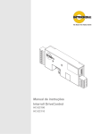
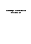
Components
05052 01925
9000
V 1.00
1
2
3
4
5
6
7
6
Fuse
Speed potentiometer
Label
Motor cable of RollerDrive
Sensor connection
Upstream connection
Digital I/O handshake (only on
HC-EC100 Full)
8
9
bl
bm
bn
bo
bp
USA
HC-EC100
REV: 0
Downstream connection
DIP switches
Warning LED (amber)
Fault LED (red)
Power LED (green)
Fuse LED (red)
Power input and I/O terminal
Version 1.0 (11/2007) en
Original language
DriveControl HC-EC100 / HC-EC110
Product information
PPLQ
PPLQ
PPLQ
PPLQ
9
86$
PPLQ
PPLQ
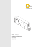
Dimensions
+&(&
5(9
Û
PPLQ
Mounting hardware
Version 1.0 (11/2007) en
Original language
PP
LQ
The following mounting hardware is supplied:
• 2x button head screw 10-32 UNF x 0.5"
• 2x nut with captive star washer 10-32 UNF
7
DriveControl HC-EC100 / HC-EC110
Product information
ZPA technology
ZPA is short for zero pressure accumulation. The HC-DriveControl provides true
zero pressure accumulation and other control options to a conveyor system.
Each HC-DriveControl controls a RollerDrive unit, which in turn drives idler
rollers using O-rings or other belts. The HC-DriveControl, the RollerDrive, and
the idler rollers (with associated sensors and switches) are assembled into a
short conveyor section – a zone.
Zero pressure accumulation occurs as zones hold packages until the next
downstream zone clears its sensor. When accumulation occurs, a low signal is
passed upstream until each consecutive zone is occupied. Packages never push
each other, and no line pressure occurs.
A logic-controlled, zero pressure conveyor is created when a number of zones
are connected together and a simple six-wire phone cable links each
HC-DriveControl electronically. The RollerDrives only operate when a package is
detected by a photoeye. If the downstream zone is empty, the package moves
forward.
Principle of zones
&
%
$
Typical ZPA conveyor configuration
1
2
3
4
Zone
Direction of travel
Load
RollerDrive
5
6
7
8
Photoeye
HC-DriveControl
Peer-to-peer communication cable
+24 VDC / GND
Zone A has a package at the photoeye. The HC-DriveControl of zone A
recognizes its presence, checks zone B for availability and requests permission
to transfer the package to zone B. Since zone B has also a package, its
HC-DriveControl denies the permission until this package has been transfered to
zone C (singulation mode), or has at least started being transfered (enhanced
singulation mode). The singulation method depends on the setting of DIP switch
SW3.
The HC-DriveControl of zone A will only start to operate the RollerDrives in its
zone after it gets permission from the HC-DriveControl of zone B.
8
Version 1.0 (11/2007) en
Original language
DriveControl HC-EC100 / HC-EC110
Product information
Product description
Features
Operation modes
Version 1.0 (11/2007) en
Original language
• Zone-to-zone communication: Activities in upstream and downstream
zones are monitored by photoeyes to permit control in various situations.
• Diagnostics: LEDs provide motor, sensor, and jam diagnostics as well as
power, fuse, and temperature status.
• Reverse or jog entire system: Switch settings and connections on the
board allow the user to reverse the zone-to-zone logic, jog the entire system,
or reverse or jog parts of the system, or bypass those functions altogether
(default) without the use of external cards.
• NPN or PNP: All inputs and outputs can be switched, collectively, for NPN or
PNP with one switch. Only "No fault output" is always active high (failsafe
function with 24 VDC in "No fault status").
• Multiple dependent RollerDrives in one zone: Up to three RollerDrives can
be run from one HC-DriveControl (and two dependent cards) to achieve
multiple RollerDrives in a single zone. This signal can also be used by a PLC
as a "motor running" status input.
• Smart braking: Depending on upstream and downstream zone occupancy,
the RollerDrive will brake if needed, and coast if no braking is required. This
saves on power, heat, and vibration in the RollerDrive and ultimately in the
system. When no photoeyes are blocked in the system, all RollerDrives are in
coast mode.
• Dynamic braking: RollerDrive acts like a generator and DriveControl feeds
back current into the RollerDrive windings.
• Zero motion hold: When the DriveControl has no start signal, the RollerDrive
will be held in place.
• Advanced braking: The combination of dynamic braking followed by zero
motion hold provides superior braking and holding for many applications.
The operation modes of a RollerDrive conveyor with HC-DriveControls include:
• Standby: The RollerDrives are turned off if the zone is empty.
• Accept: When a load reaches the sensor at the upstream end of the zone,
the RollerDrives turn on to accept it.
• Transfer: The RollerDrives continue to run to ensure that the load entering
the upstream end of the zone is transferred to the downstream end. This
creates a smooth transition and high throughput.
• Discharge: The RollerDrives in the zone continue running to discharge the
load if no accumulation command is received from the downstream zone.
9
DriveControl HC-EC100 / HC-EC110
Product information
Safety and stall functions
There are different levels of over-temperature or stall-related functions:
• Jam protection: If the HC-DriveControl detects a jam or obstruction at the
downstream end of the zone, it sends an accumulation signal to the
upstream zone, preventing a build-up of accumulation pressure that could
cause product damage or personal injury.
• Motor temperature foldback: At a motor temperature of 80 °C (176 °F) the
DriveControl will fold back peak current down to continuous current. This is
indicated by the amber LED lighting up constantly. When the RollerDrive
cools down, the amber LED extinguishes, and the maximum peak current is
now possible again. The motor can run at this reduced current limit
indefinitely without harming the DriveControl or motor.
• Motor temperature shutdown: At a motor temperature of 100 °C (212 °F)
the HC-DriveControl will shut down the motor and the motor will go into
dynamic braking. This is indicated by the red led flashing five times. When
the RollerDrive cools back down, the red LED stops flashing and motor
operation will resume.
• Motor stall current limiting: When the motor is stalled, the current will fold
back to 1.4 A until the stall is cleared.
• DriveControl temperature foldback: At a card temperature of 70 °C (158 °F)
the DriveControl will foldback peak current down to continuous current. This
is indicated by the amber LED lighting up constantly. When the DriveControl
cools down, the amber LED extinguishes, and the maximum peak current is
now possible again. The DriveControl can run at this reduced current limit
indefinitely without harming the DriveControl or motor.
• DriveControl temperature shutdown: At a DriveControl temperature of
90 °C (194 °F) the DriveControl will shutdown the motor and the motor will go
into dynamic braking. This is indicated by the red LED flashing four times.
When the DriveControl cools back down the red LED stops flashing and
motor and DriveControl operation will resume.
Incline and decline applications
Due to the zero motion hold and regenerative braking features, the
HC-DriveControl and RollerDrive EC1xx can be used for incline and decline
applications up to an angle of 15°.
10
Version 1.0 (11/2007) en
Original language
DriveControl HC-EC100 / HC-EC110
Product information
Inputs and outputs
Power input and I/O
connections
6SHHGDQDORJLQSXW
([WHUQDOSRW
6PDUW):'LQSXW
5(9LQSXW
1RIDXOWRXWSXW
6PDUWRXWSXW
&RPPRQJURXQGLQSXW
9'&LQSXW
8
7
6
5
4
3
2
1
Speed analog input: External speed control down to approximately 33% of
the maximum speed. When using a 10 kΩ external potentiometer, the wiper
must be connected here. The on-board potentiometer should be set to
maximum (CW) so it will not affect the external speed setting (for the wiring
diagrams see page 18).
External pot+: An external 10 kΩ potentiometer can be used to adjust the
speed down to approximately 33% of the maximum speed. The on-board
potentiometer should be set to maximum (CW) so it will not affect the
external speed setting (for the wiring diagrams see page 18).
Smart 1 / FWD input: Has various functions depending on zone type:
• In entry zone: acts as a start signal for the handshake with previous
machines or conveyors.
• In exit zone: acts as a start signal to discharge the conveyor as
handshake to following systems.
• In transport zone: acts as jog signal for the specific zone or the whole
conveyor (depending on the DIP switch settings)
• In dependent zone: acts as jog command to run the motor.
This input is PNP/NPN selectable (with DIP switch 1).
REV input: Invokes the system reverse function, causing all interconnected
controls to operate in reverse transport mode while the signal is active.
When in dependent mode, the motor will simply run in reverse while this
signal is active. This input is PNP/NPN selectable (with DIP switch 1).
No fault output: Active high (+24 VDC) when either in NPN or PNP mode.
Signal goes low only when system faults occur.
Smart 1 output: Has various functions depending on zone type:
• In entry zone: reflects the status of the zone (occupied or free) for
handshake with previous systems.
• In exit zone: reflects the status of the zone (occupied or free) for
handshake with following systems.
• In transport zone: is the connection to control a second RollerDrive in
the zone by interfacing with Smart 1 IN of the dependent zone.
• In dependent zone: reflects the status of the sensor.
This output is PNP/NPN selectable (with DIP switch 1).
Common ground input: Must be connect to the main power ground.
+24 VDC input: Main power supply 24 VDC (voltage range see "Technical
data", page 16).
Hint
The HC-DriveControl is protected against reverse polarity, but the power supply
must provide a short circuit or over current protection and a voltage ripple
tolerance of less than 5%.
Version 1.0 (11/2007) en
Original language
11
DriveControl HC-EC100 / HC-EC110
Product information
Sensor connection
$FFXP/VWRSLQSXW
6HQVRULQSXW
6HQVRULQSXW
6HQVRUIDXOWLQSXW
6HQVRUFRPPRQJURXQGRXWSXW
6HQVRU9'&RXWSXW
6
5
4
3
2
1
Accum (L-stop) input: An active signal (NPN/PNP switchable) on this
terminal input will cause the HC-DriveControl to accumulate in this zone until
the signal is removed. A manual switch or a PLC controller can provide the
signal referenced to a common DC ground (NPN) or +24 VDC (PNP). This
input is PNP/NPN selectable (with DIP switch 1).
Sensor 2 input: Used as a start sensor. It is located at the upstream edge of
the zone and tells the first zone in a conveyor to run. This input is PNP/NPN
selectable (with DIP switch 1).
Sensor 1 input: Located at the downstream edge of the zone. This input is
PNP/NPN selectable (with DIP switch 1).
Sensor fault input: If sensor 1 has a fault output for low gain, it can be
connected to this input. This input is PNP/NPN selectable (with DIP switch 1).
Sensor common ground output: Power ground connection for sensor 1 and
sensor 2.
Sensor +24 VDC output: +24 VDC power supply for sensor 1 and sensor 2.
Hint
Only the sensors mentioned below may be chosen: (sensor supply current from
the board is 50 mA max)
• NPN retro reflective (reflector required) - dark operate, normally open (NO)
contact
• NPN diffused (no reflector) - light operate, normally closed (NC) contact
• PNP retro reflective (reflector required) - dark operate, normally open (NO)
contact
• PNP diffused (no reflector) - light operate, normally closed (NC) contact
12
Version 1.0 (11/2007) en
Original language
DriveControl HC-EC100 / HC-EC110
Product information
Peer-to-peer communication
Even though all of the external inputs and outputs are NPN and PNP switchable,
the HC-DriveControl peer-to-peer communications always use NPN TTL logic.
This means that if a signal passing from board to board is high, it is not in
operation. If it is low (grounded), it is either performing its designated function or
sending the function signal to a nearby board.
All logic operates from a regulated and filtered 5 VDC power supply on the
HC-DriveControl. The 5 VDC power is delivered by a converter on the board
which converts the 24 VDC power that the board receives into 5 VDC for the
internal logic and peer-to-peer board communications (For communication
cable hardware see "Accessories", page 42).
Downstream peer-to-peer
6
5
4
3
2
1
Jog (I/O) [left]
Reverse (I/O)
Accumulation (I/O)
B sensor (OUT)
Ground
NPN (IN) [right]
Upstream peer-to-peer
1
2
3
4
5
6
Jog (I/O) [right]
Reverse (I/O)
Accumulation (I/O)
C sensor (IN)
NPN (IN)
Ground [left]
Hint
While different segments of a system may operate at different input voltages, the
DC ground for each system must be held at the same potential (0 VDC) to
ensure good operation and clean signals. In other words, when multiple power
supplies are used, the DC grounds must always be connected together.
Hint
When a peer-to-peer port is connected to another ZPA product, the NPN (in)
signal is pulled low except for the case where a HC-DriveControl is upstream.
Version 1.0 (11/2007) en
Original language
13
DriveControl HC-EC100 / HC-EC110
Product information
DIP switches
The DIP switches allow the selection of various types of control operations. The
default DIP switch settings are all OFF. This would provide:
• Standard HC-DriveControl connectivity upstream and downstream (SW4,
SW5)
• In standard singulate mode (SW3)
• Motor running counter clockwise (SW2)
• All NPN inputs and outputs (SW1)
Hint
DIP switch settings are read at reset (power-up) only.
/.
DIP switch settings
6:'RZQVWUHDP
6:8SVWUHDP
6:6LQJXODWLRQ
6:5RWDWLRQ
6:/RJLF
21
2YHUULGH
2YHUULGH
(QKDQFHG
&:
313
2))
6WDQGDUG
6WDQGDUG
6WDQGDUG
&&:
131
The following table shows the switch position for different situations:
14
DIP switch
ON (left position)
OFF (right position)
SW5
Downstream
Override: the downstream
peer-to-peer cable is
connected to another
HC-DriveControl and the jog/
reverse signal is transmitted
Standard: the jog/reverse
signal is not transmitted
SW4
Upstream
Override: the upstream peerto-peer cable is connected to
another HC-DriveControl and
the jog/reverse signal is
transmitted
Standard: the jog/reverse
signal is not transmitted
SW3
Singulation
Override: enhanced
singulated release (see
"Glossary", page 43) is needed
Standard: singulated release
(see "Glossary", page 43) is
needed
SW2
Rotation
Clockwise (rotation of the
RollerDrive seen from the cable
end)
Counter clockwise (rotation
of the RollerDrive seen from
the cable end)
SW1
Logic
PNP: all external inputs,
photoeye inputs and outputs
are active high (24 VDC)
NPN: all external inputs,
photoeye inputs and outputs
are active low (0 VDC ground).
This excludes the "No fault
output" which is always active
high (+24 VDC) when in either
NPN or PNP mode.
Version 1.0 (11/2007) en
Original language
DriveControl HC-EC100 / HC-EC110
Product information
Hint
• Local jog and reverse are always enabled, but upstream and downstream
propagation are controlled by DIP switch 4 and DIP switch 5 respectively.
• It is now simple to use DIP switch 4 and DIP switch 5 to define jog/reverse
groups, or to defeat jog and reverse completely (recommended whenever not
in use).
• If the RollerDrive is mounted with the cable exiting the opposite side of the
conveyor frame, switch SW2 has to be set in the opposite position to
maintain equal direction of travel.
• For special cases see "Setting options and wiring diagrams", page 19
Meaning of the LEDs
The LEDs provide motor, sensor, and jam diagnostics as well as power, fuse,
and temperature status. The following table shows the meaning of the LEDs
(flashes are ¼ second on, and ¼ second off, in a fixed 4 second time period):
LED
Color
Status
Meaning
Fuse
red
on steady (all other
LEDs are off)
Fuse blown
Power
green
on steady
Power ok
Fault
red
on steady
Stalled motor
Jam at or between sensors
flashing once
Motor or motor cable open or
disconnected
flashing twice
Over-voltage detection
29 VDC ± 0.2 VDC (will cease
normal operation)
flashing three times
Under-voltage detection
19 VDC ± 0.2 VDC (will cease
normal operation)
flashing four times
DriveControl severe temperature
shut-down (will cease normal
operation until cool)
flashing five times
Motor severe temperature shutdown (will cease normal
operation until cool)
flashing six times
Low gain or bad sensor (sensor
with fault output connected)
flashing once
Motor current is limited to
maximum continuous current due
to motor over-temperature
flashing twice
Motor current is limited to
maximum continuous current due
to card over-temperature
Warning
amber
Hint
There is no error output if the amber LED is flashing.
Version 1.0 (11/2007) en
Original language
15
DriveControl HC-EC100 / HC-EC110
Product information
DriveControl label
The specifications on the DriveControl label are used to identify the
HC-DriveControl. This is required to use the DriveControl as intended.
86$
9
1
2
3
+&(&
5(9
Serial number
Country of production
Product name
4
5
6
Revision information
Article number
Identification barcode
The serial number contains the following information about the production date:
05052 01925
1
2
3
Year
Day of the year
Sequential number of the produced units on that day
Technical data
16
Nominal voltage
24 VDC
Voltage range
22 to 28 VDC
Voltage ripple tolerance
< 5%, < 1% recommended
Continuous current
HC-EC100: 1.8 A
HC-EC110: 2.5 A
Peak current
4.1 A
Fuse
5 A slow blow Littlefuse 0452005
Protection classification
IP20
Ambient temperature for operation
0 °C to 40 °C (32 °F to 104 °F)
Ambient temperature for transport
and storage
-20 °C to 75 °C (-4 °F to 167 °F)
Ambient temperature changes
max. 1 °K/min; 3 h; two cycles
according to IEC 68-2-14
Ambient humidity
max. 90% not condensing
Installation altitude above sea level
max. 1000 m (max. 3300 ft)
Version 1.0 (11/2007) en
Original language
DriveControl HC-EC100 / HC-EC110
Product information
Speed settings
On board speed setting
The speed can be continuously adjusted (between 100% and approximately
10% for the HC-EC100 and 33% for the HC-EC110) by the potentiometer on the
DriveControl. Default setting is maximum.
Gear ratio
Speed range
EC100 + HC-EC100
EC110 + HC-EC110
4:1
–
2.41 to 0.8 m/s
(475 to 157 fpm)
9:1
–
1.07 to 0.36 m/s
(211 to 70 fpm)
12:1
1.32 to 0.15 m/s
(260 to 30 fpm)
0.8 to 0.26 m/s
(158 to 52 fpm)
16:1
1.03 to 0.1 m/s
(202 to 20 fpm)
0.6 to 0.2 m/s
(119 to 39 fpm)
24:1
0.69 to 0.13 m/s
(135 to 14 fpm)
0.4 to 0.13 m/s
(79 to 26 fpm)
36:1
0.44 to 0.05 m/s
(88 to 9 fpm)
0.27 to 0.09 m/s
(53 to 17 fpm)
48:1
0.35 to 0.04 m/s
(68 to 7 fpm)
0.2 to 0.07 m/s
(40 to 13 fpm)
64:1
0.25 to 0.03 m/s
(50 to 5 fpm)
0.15 to 0.05 m/s
(30 to 10 fpm)
96:1
0.17 to 0.02 m/s
(34 to 3 fpm)
–
Hint
If more than one DriveControl has to run with reduced speed, it is recommended
to set the speed externally (by PLC or external potentiometer; see "External
speed setting", page 18) and activate peer-to-peer communication using
DIP switch 4 (Upstream) and DIP switch 5 (Downstream).
Version 1.0 (11/2007) en
Original language
17
DriveControl HC-EC100 / HC-EC110
Product information
External speed setting
Apart from the potentiometer on the DriveControl, there are other ways to set
the speed.
Hint
When the DIP switch settings ON / OFF are stated, both settings are possible for
the shown wiring (for the meaning of the settings see "DIP switches", page 14).
'LUHFWLRQRIWUDYHO
52//(5
'5,9(
External speed set by potentiometer
6SHHGDQDORJLQSXW
([W3RW
6HQVRULQ
*1'
9'&
*1'LQSXW
9'&LQSXW
WRGRZQVWUHDP=3$FDUG
WRXSVWUHDP=3$FDUG
9'&
*1'
3RWHQWLRPHWHU
NƄ 3RWDWPLQLPXPHTXDOVRIUDWHGVSHHGIRU+&(&DQGRIUDWHGVSHHGIRU+&(&
DIP switch settings:
• SW5: ON / OFF (If SW5 is ON, speed setting is transferred downstream.)
• SW4: ON / OFF (If SW4 is ON, speed setting is transferred upstream.)
• SW3: ON / OFF
• SW2: ON / OFF
• SW1: ON / OFF
'LUHFWLRQRIWUDYHO
52//(5
'5,9(
External speed set by PLC
6SHHGDQDORJLQSXW
6HQVRULQ
*1'
9'&
*1'LQSXW
9'&LQSXW
WRGRZQVWUHDP=3$FDUG
9'&
*1'
WRXSVWUHDP=3$FDUG
9'&
*1'
3/&DQDORJVSHHGRXWSXW9'&
9 RIUDWHGVSHHGIRU+&(&
9 RIUDWHGVSHHGIRU+&(&
9 RIUDWHGVSHHG
DIP switch settings:
• SW5: ON / OFF (If SW5 is ON, speed setting is transferred downstream.)
• SW4: ON / OFF (If SW4 is ON, speed setting is transferred upstream.)
• SW3: ON / OFF
• SW2: ON / OFF
• SW1: ON / OFF
18
Version 1.0 (11/2007) en
Original language
DriveControl HC-EC100 / HC-EC110
Product information
Setting options and wiring diagrams
This chapter explains the DIP switch settings for different applications.
Hint
When the DIP switch settings ON / OFF are stated, both settings are possible for
the shown wiring (for the meaning of the settings see "DIP switches", page 14).
HC-DriveControl is between
two HC-DriveControls
Upstream device
HC-DriveControl
Downstream device
HC-DriveControl
DIP switch 4
Off
On
Off
On
DIP switch 5
Off
On
On
Off
Upstream peer-to-peer
jog/reverse
Disabled
Functional
Disabled
Functional
Downstream peer-to-peer
jog/reverse
Disabled
Functional
Functional
Disabled
Zone type
ZPA-mode ZPA-mode ZPA-mode ZPA-mode
Smart 1 (in)
Jog
Jog
Jog
Jog
Reverse (in)
System
reverse
System
reverse
System
reverse
System
reverse
Smart 1 (out)
Motor run
Motor run
Motor run
Motor run
Sensor 2
Another
C sensor
Another
C sensor
Another
C sensor
Another
C sensor
'LUHFWLRQRIWUDYHO
*1'
9'&
WRGRZQVWUHDP=3$FDUG
9'&
*1'
52//(5
'5,9(
Standard configuration
6HQVRULQ
*1'
9'&
WRXSVWUHDP=3$FDUG
9'&
*1'
DIP switch settings:
• SW5: ON / OFF
• SW4: ON / OFF
• SW3: ON / OFF
• SW2: ON / OFF
• SW1: ON / OFF
Version 1.0 (11/2007) en
Original language
19
DriveControl HC-EC100 / HC-EC110
Product information
'LUHFWLRQRIWUDYHO
52//(5
'5,9(
Accumulation (L-stop) in PNP mode
$FFXPLQ/VWRS
6HQVRULQ
*1'
9'&
*1'
9'&
WRGRZQVWUHDP=3$FDUG
WRXSVWUHDP=3$FDUG
9'&
*1'
9'&
*1'
DIP switch settings:
• SW5: ON / OFF
• SW4: ON / OFF
• SW3: ON / OFF
• SW2: ON / OFF
• SW1: ON
'LUHFWLRQRIWUDYHO
52//(5
'5,9(
Accumulation (L-stop) in NPN mode
$FFXPLQ/VWRS
*1'
9'&
WRGRZQVWUHDP=3$FDUG
9'&
*1'
6HQVRULQ
*1'
9'&
WRXSVWUHDP=3$FDUG
9'&
*1'
DIP switch settings:
• SW5: ON / OFF
• SW4: ON / OFF
• SW3: ON / OFF
• SW2: ON / OFF
• SW1: OFF
20
Version 1.0 (11/2007) en
Original language
DriveControl HC-EC100 / HC-EC110
Product information
'LUHFWLRQRIWUDYHO
5HYHUVHGLUHFWLRQRIWUDYHO
52//(5
'5,9(
External direction set in PNP mode
6PDUW)ZGLQ
5HYLQ
6HQVRULQ
*1'
9'&
*1'
9'&
WRGRZQVWUHDP=3$FDUG
5(9LQ
WRXSVWUHDP=3$FDUG
9'&
*1'
):'LQ
DIP switch settings:
• SW5: ON / OFF (If SW5 is ON, direction setting is transferred downstream.)
• SW4: ON / OFF (If SW4 is ON, direction setting is transferred upstream.)
• SW3: ON / OFF (If REV signal is active, SW3 has to be OFF.)
• SW2: ON / OFF
• SW1: ON
Start options:
• FWD connected to 24 VDC at PNP mode causes ccw rotation.
• REV connected to 24 VDC at PNP mode causes cw rotation.
• FWD and REV connected to 24 VDC at PNP mode causes coast mode.
Hint
• FWD signal acts like a jog signal, disregarding ZPA functionality and
photoeye signals.
• REV signal reverses motor and logic direction; upstream becomes
downstream and C sensor becomes B sensor.
Version 1.0 (11/2007) en
Original language
21
DriveControl HC-EC100 / HC-EC110
Product information
'LUHFWLRQRIWUDYHO
5HYHUVHGLUHFWLRQRIWUDYHO
52//(5
'5,9(
External direction set in NPN mode
6PDUW)ZGLQ
5HYLQ
6HQVRULQ
*1'
9'&
*1'
9'&
WRGRZQVWUHDP=3$FDUG
5(9LQ
WRXSVWUHDP=3$FDUG
9'&
*1'
):'LQ
DIP switch settings:
• SW5: ON / OFF (If SW5 is ON, direction setting is transferred downstream.)
• SW4: ON / OFF (If SW4 is ON, direction setting is transferred upstream.)
• SW3: ON / OFF (If REV signal is active, SW3 has to be OFF.)
• SW2: ON / OFF
• SW1: OFF
Start options:
• FWD connected to GND at NPN mode causes ccw rotation.
• REV connected to GND at NPN mode causes cw rotation.
• FWD and REV connected to GND at NPN mode causes coast mode.
Hint
• FWD signal acts like a jog signal, disregarding ZPA functionality and
photoeye signals.
• REV signal reverses motor and logic direction; upstream becomes
downstream and C sensor becomes B sensor.
22
Version 1.0 (11/2007) en
Original language
DriveControl HC-EC100 / HC-EC110
Product information
'LUHFWLRQRIWUDYHO
WRXSVWUHDP=3$FDUG
WRGRZQVWUHDP=3$FDUG
9'&
*1'
6HQVRULQ
*1'
9'&
52//(5
'5,9(
Left to right conveyor
9'&
*1'
*1'
9'&
DIP switch settings:
• SW5: ON / OFF
• SW4: ON / OFF
• SW3: ON / OFF
• SW2: ON / OFF
• SW1: ON / OFF
Hint
Works like a standard configuration, only the HC-DriveControl is turned upsidedown.
Version 1.0 (11/2007) en
Original language
23
DriveControl HC-EC100 / HC-EC110
Product information
6PDUWRXW
*1'
9'&
52//(5
'5,9(
52//(5
'5,9(
'LUHFWLRQRIWUDYHO
52//(5
'5,9(
Multiple RollerDrives in one zone
=RQH'ULYH&RQWURO
6HQVRULQ
*1'
9'&
WRGRZQVWUHDP
=3$FDUG
WRXSVWUHDP
=3$FDUG
6PDUWLQ
*1'
9'&
'HSHQGHQW
'ULYH&RQWUROV
6PDUWLQ
*1'
9'&
9'&
*1'
9'&
*1'
Hint
A reverse command to the Zone DriveControl will not be communicated to the
dependent DriveControls.
Zone DriveControl DIP switch settings:
• SW5: OFF
• SW4: OFF
• SW3: ON / OFF
• SW2: ON / OFF
• SW1: ON / OFF
Dependent DriveControl DIP switch settings:
• SW5: OFF
• SW4: OFF
• SW3: OFF
• SW2: ON / OFF
• SW1: ON / OFF (must have the same switch setting as zone DriveControl
(logic mode NPN or PNP))
24
Version 1.0 (11/2007) en
Original language
DriveControl HC-EC100 / HC-EC110
Product information
'5,9(
'LUHFWLRQRIWUDYHO
52//(5
HC-DriveControl as motor control board
6PDUWLQ):'FRPPDQG
!IRU131*1'LQ
!IRU3139'&LQ
5(9FRPPDQG
!IRU131*1'LQ
!IRU3139'&LQ
*1'
9'&
9'&
*1'
DIP switch settings:
• SW5: OFF
• SW4: OFF
• SW3: OFF
• SW2: ON / OFF
• SW1: ON / OFF
Start options:
• FWD connected to 24 VDC causes ccw rotation.
• REV connected to 24 VDC causes cw rotation.
• FWD and REV connected to 24 VDC causes coast mode.
Version 1.0 (11/2007) en
Original language
25
DriveControl HC-EC100 / HC-EC110
Product information
HC-DriveControl is entry zone
Upstream device
-
-
Downstream device
-
-
HC-DriveControl
DIP switch 4
Off
On
Off
On
DIP switch 5
Off
On
On
Off
Upstream peer-to-peer
jog/reverse
Disabled
Functional
Disabled
Functional
Downstream peer-to-peer
jog/reverse
Disabled
Functional
Functional
Disabled
Zone type
Smart I/O
entry
ZPA-mode Smart I/O
entry
ZPA-mode
Smart 1 (in)
Request
Jog
Request
Jog
Reverse (in)
System
reverse
System
reverse
System
reverse
System
reverse
Smart 1 (out)
Perm.
Motor run
Perm.
Motor run
Sensor 2
Not used
(smart I/O)
Another
C sensor
Not used
(smart I/O)
Another
C sensor
'LUHFWLRQRIWUDYHO
52//(5
'5,9(
Standard configuration with PLC or photoeye start command
3/&VWDUW
FRPPDQG
*1'
9'&
6HQVRULQ
6HQVRULQ
*1'
9'&
WRGRZQVWUHDP=3$FDUG
9'&
*1'
DIP switch settings:
• SW5: ON / OFF
• SW4: ON / OFF (specifies if this zone is a transport or entry zone; if
sensor 2 IN is used, SW 4 must be set to ON)
• SW3: ON / OFF
• SW2: ON / OFF
• SW1: ON / OFF
Sensor 2 IN start signal (by PLC or photoeye):
• Start signal for PNP: 24 VDC
• Start signal for NPN: GND
Hint
If you are using a photoeye as a starting signal, connect sensor 2 IN with the
photoeye.
26
Version 1.0 (11/2007) en
Original language
DriveControl HC-EC100 / HC-EC110
Product information
HC-DriveControl is exit zone
Upstream device
HC-DriveControl
Downstream device
-
-
-
-
DIP switch 4
Off
On
Off
On
DIP switch 5
Off
On
On
Off
Upstream peer-to-peer
jog/reverse
Disabled
Functional
Disabled
Functional
Downstream peer-to-peer
jog/reverse
Disabled
Functional
Functional
Disabled
Zone type
Smart I/O
entry
ZPA-mode ZPA-mode Smart I/O
entry
Smart 1 (in)
Perm.
Jog
Jog
Perm.
Reverse (in)
System
reverse
System
reverse
System
reverse
System
reverse
Smart 1 (out)
Request
Motor run
Motor run
Request
Sensor 2
Another
C sensor
Another
C sensor
Another
C sensor
Another
C sensor
'LUHFWLRQRIWUDYHO
52//(5
'5,9(
Standard configuration with "Smart 1 IN" start command
6PDUWLQ
*1'
9'&
6HQVRULQ
*1'
9'&
WRXSVWUHDP=3$FDUG
9'&
*1'
9'&
*1'
DIP switch settings:
• SW5: ON / OFF (specifies if this zone is a transport or exit zone)
• SW4: ON / OFF
• SW3: ON / OFF
• SW2: ON / OFF
• SW1: ON / OFF
Smart 1 IN signal (by PLC or photoeye):
• Start signal for PNP: 24 VDC
• Start signal for NPN: GND
Version 1.0 (11/2007) en
Original language
27
DriveControl HC-EC100 / HC-EC110
Product information
HC-EC100 Full in conjunction
with Z-Cards EC
Only the HC-EC100 Full (Art. # 9001) is equipped with a digital I/O-handshake
terminal. It is specially designed for easy Z-Card EC connection. HC-EC110 is
not available with digital I/O-handshake terminal.
HC-EC100
Full between
Z-Cards
HC-EC100 Full before Z-Card
Upstream device
Z-Card EC
Downstream device
Z-Card EC
Z-Card EC
Z-Card EC
DIP switch 4
Off
Off
On
Off
Off
DIP switch 5
Off
Off
Off
Off
On
Upstream peer-to-peer jog/reverse
Disabled
Disabled
Functional
Disabled
Disabled
Downstream peer-to-peer jog/
reverse
Disabled
Disabled
Disabled
Disabled
Functional
Digital I/O on board
Yes
Yes
Yes
Yes
Yes
Zone type
Digital
I/O
dependent
Digital
I/O exit
Digital
I/O exit
Digital
I/O entry
Digital
I/O entry
Smart 1 (in)
Jog
Jog
Jog
Jog
Jog
Reverse (in)
System
reverse
System
reverse
System
reverse
System
reverse
System
reverse
Smart 1 (out)
B sensor
B sensor
B sensor
B sensor
B sensor
Sensor 2
Not used
(digital I/O)
Another
C sensor
Another
C sensor
Not used
(digital I/O)
Not used
(digital I/O)
Req (out)
N/C
N/C
N/C
In use
In use
Perm (in)
N/C
N/C
N/C
In use
In use
Req (out)
In use
In use
In use
N/C
N/C
Perm (in)
In use
In use
In use
N/C
N/C
Upstream digital I/O
Downstream digital I/O
28
HC-EC100 Full
HC-EC100 Full after Z-Card
Z-Card EC
Z-Card EC
HC-EC100 Full
Version 1.0 (11/2007) en
Original language
DriveControl HC-EC100 / HC-EC110
Product information
52//(5
'5,9(
Standard configuration
'LUHFWLRQRIWUDYHO
=&DUG(&
0RW
'R7
6SHHG6HOHFWRU
0RW
+7%/+3%/
0RW
):'5(9
6HQV
)XVH
6HQV
):'5(9
96XS
6HQV
6(16,19
6HQV
96XS
6(16,19
6HQV
6HQV
'R7
+7%/+3%/
)XVH
6HQV
6HQV
96XS
'R7
6SHHG6HOHFWRU
0RW
96XS
3*0
3*0
313131
313131
8S
636
6HQV
636
'RZQ
636
8S
636
636
6HQV
636
/('
636
'RZQ
636
0RW
=&DUG(&
'R7
0RW
0RW
0RW
6HQVRULQ
*1'
9'&
*1'
9'&
=&DUG(&
=&DUG(&
/('
636FRQQHFWRU
636FRQQHFWRU
'LJLWDO,2KDQGVKDNHFRQQHFWRU
9'&
*1'
9'&
*1'
DIP switch settings:
• SW5: ON / OFF
• SW4: ON / OFF
• SW3: ON / OFF
• SW2: ON / OFF
• SW1: ON / OFF
Digital I/O connection to Z-Card
'LUHFWLRQRIWUDYHO
=&DUG(&
'R7
=&DUG(&
'R7
6SHHG6HOHFWRU
0RW
+7%/+3%/
6HQV
):'5(9
)XVH
6HQV
'R7
+7%/+3%/
):'5(9
96XS
6HQV
6(16,19
6HQV
96XS
6HQV
3*0
6(16,19
6HQV
'R7
6SHHG6HOHFWRU
6HQV
)XVH
6HQV
96XS
0RW
0RW
0RW
0RW
96XS
3*0
313131
313131
8S
636
6HQV
636
'RZQ
8S
636
636
636
636
6HQV
636
'RZQ
636
0RW
0RW
0RW
/('
/('
,QSXW
9'&2XWSXW
(PLWWHU
&ROOHFWRU
=&DUG(&
,QSXW
9'&2XWSXW
(PLWWHU
&ROOHFWRU
636FRQQHFWRU
=&DUG(&
636FRQQHFWRU
+&(&)XOO
Version 1.0 (11/2007) en
Original language
29
DriveControl HC-EC100 / HC-EC110
Product information
HC-DriveControl in
conjunction with PLChandshakes
HC-DriveControl after
PLC-handshake (entry zone)
Upstream device
Downstream device
HC-DriveControl before
PLC-handshake (exit zone)
HC-DriveControl
between PLChandshakes
PLC
HC-DriveControl
PLC
HC-DriveControl
PLC
PLC
DIP switch 4
Off
Off
Off
On
Off
DIP switch 5
Off
On
Off
Off
Off
Upstream peer-to-peer jog/reverse
Disabled
Disabled
Disabled
Functional
Disabled
Downstream peer-to-peer jog/
reverse
Disabled
Functional
Disabled
Disabled
Disabled
Zone type
Smart I/O
entry
Smart I/O
entry
Smart I/O exit Smart I/O exit Smart I/O
dependent
Smart 1 (in)
Request
Request
Perm.
Perm.
Run
Reverse (in)
System
reverse
System
reverse
System
reverse
System
reverse
System reverse
Smart 1 (out)
Perm.
Perm.
Request
Request
B sensor
Sensor 2
Not used
(smart I/O)
Not used
(smart I/O)
Another
C sensor
Another
C sensor
Not used
'LUHFWLRQRIWUDYHO
52//(5
'5,9(
HC-DriveControl after PLC-handshake (entry zone)
6PDUWLQXSVWUHDPUHTXHVW
9'&LQIRU313*1'IRU131
6PDUWRXWXSVWUHDPSHUPLVVLRQ
9'&RXWIRU313*1'IRU131
*1'
9'&
6HQVRULQ
*1'
9'&
WRGRZQVWUHDP
=3$FDUG
9'&
*1'
DIP switch settings:
• SW5: ON / OFF
• SW4: OFF
• SW3: ON / OFF
• SW2: ON / OFF
• SW1: ON / OFF
Hint
• A smart I/O based handshake is required at the interface
• DIP switch 4 must be OFF to make this zone into an entry zone
• Jog and reverse are enabled only if DIP switch 5 is ON
30
Version 1.0 (11/2007) en
Original language
DriveControl HC-EC100 / HC-EC110
Product information
52//(5
'5,9(
HC-DriveControl before PLC-handshake (exit zone)
'LUHFWLRQRIWUDYHO
6PDUW,1GRZQVWUHDPSHUPLVVLRQ
9'&,1IRU313*1'IRU131
6PDUW287GRZQVWUHDPUHTXHVW
9'&287IRU313*1'IRU131
6HQVRULQ
*1'
9'&
*1'
9'&
WRXSVWUHDP
=3$FDUG
9'&
*1'
9'&
*1'
DIP switch settings:
• SW5: OFF
• SW4: ON / OFF
• SW3: ON / OFF
• SW2: ON / OFF
• SW1: ON / OFF
Hint
• A smart I/O based handshake is required at the interface
• DIP switch 5 must be OFF to make this zone into an exit zone
• Jog and reverse are enabled only if DIP switch 4 is ON
'5,9(
'LUHFWLRQRIWUDYHO
52//(5
HC-DriveControl between two PLC-handshakes
6PDUWLQUXQVLJQDO
9'&LQIRU313DQG*1'IRU131
6PDUWRXWGRZQVWUHDQHGJHSUHVHQFHVHQVRU
9'&RXWIRU313DQG*1'IRU131
*1'
9'&
6HQVRULQ
*1'
9'&
9'&
*1'
DIP switch settings:
• SW5: OFF
• SW4: OFF
• SW3: ON / OFF
• SW2: ON / OFF
• SW1: ON / OFF
Hint
• A smart I/O based handshake is required at both interfaces
• DIP switch 4 and DIP switch 5 must both be OFF to make this zone into a
dependent zone.
Version 1.0 (11/2007) en
Original language
31
DriveControl HC-EC100 / HC-EC110
Transport and storage
Transport
Transport and storage
• Each DriveControl is packed in its own carton case.
CAUTION
Risk of injury due to improper transport
¾ Transport may only be carried out by qualified and
authorized persons.
¾ Observe the following notices.
¾
¾
¾
¾
¾
¾
Do not stack more than four carton boxes.
Check the fixation of the DriveControls before transport.
Avoid hard shocks during transport.
Check each DriveControl visually for damage after transport.
In case of damage, take photos of the damaged parts.
To maintain the warranty, report any damage caused by transport instantly to
the transport company and Interroll.
¾ Do not transfer the DriveControls between warm and cold environments. This
may cause condensing water.
Storage
CAUTION
Risk of injury due to improper storage
¾ Do not stack more than four carton boxes.
¾ Check each DriveControl for damage after storage.
32
Version 1.0 (11/2007) en
Original language
DriveControl HC-EC100 / HC-EC110
Assembly
Warning notices concerning assembly
Assembly
Risk of damage leading to failure or shortened life
expectancy of the DriveControl
¾ Observe the following notices.
¾ Do not drop or mishandle the DriveControl to avoid internal damage.
¾ Check each DriveControl visually for damage before assembly.
Warning notices concerning the electrical installation
Risk of damage to the DriveControl
¾ Observe the following notices.
¾ The electrical installation may only be executed by qualified and authorized
persons.
¾ Disconnect the power before installing, removing or rewiring the
DriveControl.
¾ Do not apply AC current to the RollerDrive or DriveControl device at any time
as this will cause irreparable damage.
¾ Do not apply too much stress to the connector pins. Bending the wires at the
connector can cause damage to the insulation of the wires, which could
result in failure of the DriveControl or the RollerDrive.
¾ Ensure that the RollerDrive, the DriveControl and the 24 VDC power source
are properly earthed through the frame or supporting structure in which the
RollerDrive and the DriveControl are installed. Failure to do so could cause
the buildup of static electricity or ground loops and can cause the motor or
DriveControl to malfunction or fail prematurely.
¾ Do not spin the RollerDrive manually, as this generates an induction voltage
which could damage the DriveControl.
Installing the HC-DriveControl in a conveyor system
¾ Use the DriveControl as a template and mark the center of the two mounting
holes. For the distance between the holes, see "Dimensions", page 7.
¾ Drill two ø 5.6 - 6 mm (0.22 - 0.24 in) mounting holes at the marked spots.
¾ Insert the button head screws in the holes on the opposite side the
DriveControl is to be mounted.
¾ Install the DriveControl to the frame with the screws protruding through the
mounting holes.
¾ Slip the nuts to the screws and tighten.
¾ Ensure that there is a ground path between the DriveControl and the
conveyor frame it is mounted to.
Hint
The DriveControl and conveyor frame should be at the same potential
referenced to earth ground.
Version 1.0 (11/2007) en
Original language
33
DriveControl HC-EC100 / HC-EC110
Assembly
Electrical installation
The connector supplied with the RollerDrive EC1xx mates up with the header on
the DriveControl.
The connectors "Power input and I/O terminal" and "Sensor connection" are
cage clamp terminals.
¾ To actuate the cage clamp, use the supplied tool or insert a small
screwdriver.
¾ Plug in the RollerDrive connector.
¾ Plug in the peer-to-peer connection cable, if applicable.
34
Version 1.0 (11/2007) en
Original language
DriveControl HC-EC100 / HC-EC110
Initial startup and operation
Initial startup
Initial startup and operation
Inspections before initial
startup
¾ Ensure that all bolts are tightened according to the specifications.
¾ Ensure that no additional dangerous areas arise due to interfaces to other
components.
¾ Ensure that the wiring is in accordance with the specification and legal
directives.
¾ Check all protection devices.
¾ Ensure that no bystanders are in dangerous areas around the conveyor.
Operation
Damage to the DriveControl or the motor of the
RollerDrive due to induction
¾ Do not push items along the roller conveyor by hand.
¾ Do not spin the RollerDrive manually.
Inspections before every
startup
¾ Check the position of the DIP switches (see "DIP switches", page 14).
¾ Check the speed settings at the speed potentiometer. It is recommended to
run the RollerDrive at maximum speed.
¾ Check the DriveControl for visible damage.
¾ Check all protection devices.
¾ Ensure that no bystanders are in dangerous areas around the conveyor.
¾ Clearly specify and monitor the way goods are placed on the conveyor.
Changing settings
¾ To reduce the speed manually, turn the potentiometer counterclockwise with
a small screwdriver.
¾ To increase the speed manually, turn the potentiometer clockwise with a
small screwdriver.
¾ To set the DIP switches, carefully use a small screwdriver.
Procedure in case of accident or malfunction
¾
¾
¾
¾
¾
Version 1.0 (11/2007) en
Original language
Stop the conveyor at once and ensure that it cannot be started accidentally.
In case of an accident: Provide first aid and make an emergency call.
Inform the responsible person.
Have the malfunction repaired by qualified persons.
Start the conveyor only after this has been approved by qualified persons.
35
DriveControl HC-EC100 / HC-EC110
Maintenance and cleaning
Warning notices concerning maintenance and cleaning
Maintenance and cleaning
CAUTION
Risk of injury due to improper handling or accidental
motor starts
¾ Maintenance work and cleaning may only be executed
by qualified and authorized persons.
¾ Only perform maintenance work after switching off the
power. Ensure that the DriveControl cannot be turned
on accidentally.
¾ Set up signs indicating maintenance work.
Maintenance
Checking the DriveControl
The DriveControl must be checked at regular intervals to avoid malfunctions.
¾ Monthly check the DriveControl and its leads for visible damage.
¾ Annually ensure that the screws of the DriveControl are still tight and that the
cables are still laid properly and connected to the terminals.
Replacing the DriveControl
If a DriveControl is damaged, it has to be replaced.
¾ Install a new DriveControl (see "Abandonment", page 41 and see
"Assembly", page 33).
Replacing fuse
¾ Carefully use tweezers to remove and insert the fuse. Ensure you do not
damage the fuse holder, the circuit board or its devices.
Cleaning
Dust and dirt in combination with humidity may bridge the electric circuit.
Therefore, in a dirty environment, periodic cleaning will help to avoid shortcircuits which could damage the DriveControl.
¾ Regularly blow off dust and dirt with low compressed air.
36
Version 1.0 (11/2007) en
Original language
DriveControl HC-EC100 / HC-EC110
Troubleshooting
Error search
Troubleshooting
When troubleshooting the conveyor system, keep in mind that each
HC-DriveControl controls a zone. If a problem exists in a zone or a section of
zones, the symptoms might exist either in the zone or in the neighboring zone.
Hint
Keep in mind that information travels downstream. The cause of most control
problems can be found upstream.
Symptom
Possible cause
Help
System is not operating
No power supply
Check whether the output voltage of
the power supply is within the specified
voltage range.
Wrong polarity of the bus line inputs
Verify the polarity of the bus line inputs
to DriveControl (see "Inputs and
outputs", page 11).
Wrong position of the DIP switch 1
Verify that the position of the DIP switch
1 Logic (NPN or PNP) matches the
sensor type (see "DIP switches",
page 14).
Fuse is blown
Replace the fuse (see "Replacing fuse",
page 36).
Wrong sensor output
Check the type of sensor output (see
"Sensor connection", page 12).
Wrong alignment of sensors
Verify the alignment of the sensors.
Align the photoeyes to see the conveyor
field only, no overhead lights, side
frames, etc.
Jog command by an inadvertently
grounded Smart 1 / FWD input
command
Check the connection of Smart 1 / FWD
input
Communication cable is twisted or
defective
Check the communication cable
upstream
Photoeye is not connected properly
Check the connection of the photoeye
to HC-DriveControl. Verify the photoeye
pin assignment (see "Sensor
connection", page 12).
Photoeye is damaged
Replace the photoeye.
If the zone continues to run without
any communication cables
connected and no photoeye input,
HC-DriveControl is damaged.
Replace HC-DriveControl. Assembly of
the DriveControl see "Assembly",
page 33.
Zone runs without package
Version 1.0 (11/2007) en
Original language
37
DriveControl HC-EC100 / HC-EC110
Troubleshooting
Symptom
Possible cause
Help
Multiple zones run continuously
Communication cable is defective,
sending a jog command
Find the farthest zone in the upstream
direction that is running continuously.
Check the communication cables of this
zone.
Different ground of a multiple power
supply
Verify that a common ground is shared
by all supplies.
Fuse is blown
If DIP switch 4 and 5 are ON for all
cards, a blown fuse or loss of power
in one DriveControl sends a reverse
jog command to all DriveControls in
the system.
Check the fuses in all DriveControls of
the system and replace the blown one
(see "Replacing fuse", page 36).
Miswired communication cable
Check the communication cables in the
entry zone of the system. Replace the
miswired cables.
System reverses or jogs without
prompting
Zone stops when package arrives
Zone does not accept package
Package stops within a zone
38
Zone receives the accumulate signal Check that the zone is not receiving the
accumulate signal from the downstream
zone.
Ensure that there is no jumper installed
from ground to the Accum (L-stop)
input terminal on the HC-DriveControl
of the zone where the package stops. If
a switch is used instead of a jumper,
check that the switch is off.
Communication cable to or between
the zones is miswired
Check the communication cables and
replace them if they are miswired.
No power supply of the
HC-DriveControl
Check the power input to
HC-DriveControl
No power supply of the RollerDrive
EC1xx
Verify that the motor wires are
terminated properly.
Communication cable is miswired
between the zone that is operating
and the zone that is not
Replace the cable.
Photoeye is not aligned properly
Check the alignment of the photoeye.
Speed of the RollerDrive EC1xx is
too slow
Calculate the speed and the distance to
ensure the time limit is not exceeded.
The package has max. 4.5 seconds to
clear the upstream photoeye and reach
the next downstream photoeye.
Adjust the speed of the RollerDrive.
Jammed package
Remove jammed packages.
Jammed roller
Remove the cause of the jam or replace
the roller.
Version 1.0 (11/2007) en
Original language
DriveControl HC-EC100 / HC-EC110
Troubleshooting
Symptom
Possible cause
Help
Package coasts into the next zone
instead of stopping immediately
Package is heavy or has a low
coefficient of friction
Move the photoeye further back into the
zone.
Apply a coating that increases the
friction between the rollers and the
packages.
Zone does not reverse
Communication cable to upstream
zone is miswired
Replace the communication cable.
Signal has not been sent and
received properly
Check the output of the upstream
DriveControl and the input to the
DriveControl.
Different ground of the zones
Check that a common ground exists
between both zones.
System turns off when several zones
are in use at the same time
Power supply is not sufficient
Ensure that the 24 VDC power supply
has adequate power for the system
requirements.
Check that the AC voltage source and
DC voltage power supply are installed
correctly.
DriveControl does not recognize the
start sensor
Sensor and reflector are not aligned
properly
Check the alignment of the sensor and
reflector.
Check the settings of DIP switch 4
and 5.
RollerDrive EC1xx is not in braking
mode without any packages on the
conveyor system
This is not an error. It is a powersaving feature. The RollerDrive
EC1xx is in coast mode until it is
commanded to run or accumulate.
Version 1.0 (11/2007) en
Original language
39
DriveControl HC-EC100 / HC-EC110
Troubleshooting
The following errors are reported by illuminated LEDs:
(also see "Meaning of the LEDs", page 15)
Symptom
Possible cause
Help
Motor is in brake mode, red fault
LED flashes once and error output is
active ("No fault output" is active).
Invalid state of motor hall effect
sensor
• Broken wire
• Failed hall effect sensor
Replace the RollerDrive.
Voltage over or under limits
• Power supply fluctuations, failure
or overload condition
Check the power supply.
On a decline, motor is in brake mode
momentarily. Red fault LED flashes
twice ("No fault output" is active) or
power supply shutdown or fuse
blown on card.
Overvoltage detection (caused by
over speed or excessive back EMF)
• decline angle too high
• package weight too high
• Reduce decline angle
• Use brake roller to keep speed low
Motor overrun, overset speed
• Package enters zone at a higher
than anticipated speed
Reduce the package entry speed.
Red fault LED flashes six times and
error output is active ("No fault
output" is active).
Low gain signal from sensor
• Dirty sensor lens or misaligned
Clean the sensor lens and align the
sensor.
Current folds back to maximum
continuous current, amber fault LED
is on.
Card or motor over temperature
• Excessive load or duty cycle
Reduce the load of packages or
throughput of the zone
Current folds back to approximately
1.5 A while applying consistent
torque. Red fault LED is on and error
output is active ("No fault output" is
active).
Motor stall condition
• Obstruction or load too heavy to
be conveyed
Once the stall condition is removed, the
RollerDrive will resume normal
operation.
40
Version 1.0 (11/2007) en
Original language
DriveControl HC-EC100 / HC-EC110
Abandonment and disposal
Abandonment
Abandonment and disposal
CAUTION
Risk of injury due to improper handling
¾ Abandonment may only be executed by qualified and
authorized persons.
¾ Only abandon the DriveControl after switching off the
power. Ensure that the DriveControl cannot be turned
on accidentally.
¾ Disconnect all cables from the DriveControl.
¾ Unscrew the screws attaching the DriveControl to the conveyor frame.
¾ Extract the DriveControl from the conveyor frame.
Disposal
The operator is responsible for the proper disposal of the DriveControl. In doing
so, industry-specific and local provisions must be observed for the disposal of
the DriveControl and its packaging.
Version 1.0 (11/2007) en
Original language
41
DriveControl HC-EC100 / HC-EC110
Appendix
Accessories
Appendix
DriveControls
Plugs and cables
Part
Part #
Z-Card EC Easy
89Z2
Z-Card EC Full
89Z3
Part
Description
Power and I/O plug
• 8-pin cage clamp type connector, Wago part #
231-308/026-004
• Wire diameter:
– Minimum 0.08 mm2 (AGW 28)
– Maximum 2.5 mm2 (AGW 12)
Sensor plug
• 6-pin cage clamp type connector, Wago part #
734-106/000-004
• Wire diameter:
– Minimum 0.08 mm2 (AGW 28)
– Maximum 1.5 mm2 (AGW 14)
Peer-to-peer cable
• Cable: 6 pos flat cable, SPC technology part #
TXW6205-WF
• Two plugs: 6 pos AMP modular connector plug,
AMP part # 5-641337-3
• Conductor Size AWG: 24
• Assembly tool: AMP part # 2-231652-8
Dig. I/O plug (only on
HC-EC100 Full #9001)
• Double-stack header on the board, Phoenix
Contact socket, part # 1961164
• Plugs: Phoenix Contact part # 1881341
Motor plug
• The motor plug for the RollerDrive consists of a
plug and terminal pins
– Plug: AMP part # 175778-8
– Terminal pins: AMP part # 1-175102-1
• Crimping tool AMP part # 9184381
42
Version 1.0 (11/2007) en
Original language
DriveControl HC-EC100 / HC-EC110
Appendix
Glossary
Back EMF
Electromotive force (voltage) generated by a package arriving at high speed at
a powered RollerDrive under no load prior to the package’s arrival. EMF is a
counter-voltage phenomenon that is always present in a motor. Excessive
back EMF can cause a current backlash that may damage the DriveControl or
power supply. Care should be taken to minimize excessive back EMF by
minimizing the speed differences between the gravity conveyor and/or
different zones of powered conveyor sections.
B sensor
Downstream edge presence sensor of own zone
C sensor
Downstream edge presence sensor of upstream zone
Coast mode
Digital I/O
The RollerDrive is running freely without power or braking.
Software automatically detects if circuitry is on board
(Digital I/O handshake only on HC-EC100 Full available)
DIP switch 4
Affects upstream peer-to-peer propagation of speed, jog and reverse signals
for certain scenarios.
DIP switch 5
Affects downstream peer-to-peer propagation of speed, jog and reverse
signals for certain scenarios.
Downstream
Normally this is the zone to the left of another given zone. The reference is
always that packages move from upstream to downstream.
Dynamic braking
EC1xx
For DC motors, dynamic braking is a method of stopping a motor by applying
a resistive load across the motor winding leads after disconnection from the
DC supply. The motor operates as a generator. By its nature, dynamic braking
has no holding power by itself, i.e. the motor can still be rotated by outside
forces. Interroll has added zero motion hold to achieve this.
Short form for Interroll 24 VDC brushless RollerDrive versions:
• EC100
• EC110
Edge full
Also referred to as "product waiting". It indicates that an upstream zone has a
product at its downstream edge sensor waiting to be moved into the next
downstream zone. Edge full is a signal transmitted across the peer-to-peer
cable used by the HC-DriveControl for zone-to-zone communication.
Enhanced Singulated release
Also called wave release. A method of release which allows the upstream
release of a package as soon as the downstream package blocks the
photoeye of the downstream zone with its leading edge. This dramatically
increases throughput over singulated release but can sometimes result in lost
packages. There is also a short delay that is propagated upstream to eliminate
all packages starting at the exact same time.
Foldback current
Maximum allowable current is decreased by the DriveControl.
HC-DriveControl
Short form for a single zone DriveControl for Interroll 24 VDC brushless
RollerDrives:
• HC-EC100: Can be used as DriveControl (motor control) and as ZPA zone
control for RollerDrives EC100
• HC-EC110: Can be used as DriveControl (motor control) and as ZPA zone
control for RollerDrives EC110
Version 1.0 (11/2007) en
Original language
43
DriveControl HC-EC100 / HC-EC110
Appendix
Idler rollers
Jam protection
A method of protecting packages that are possibly jammed in a zone. If the
HC-DriveControl detects a jam or obstruction at the downstream end of the
zone, it sends an accumulation signal to the upstream zone preventing a
buildup of accumulation pressure.
Jog
RollerDrive runs continuously as long as the command is set. If jog mode is
activated, DriveControl disregards ZPA or photoeye signals.
N/C
No care; affects nothing
NPN-override
O-rings
Perm
Photoeye
Req
RollerDrive
Singulated release
DIP switch 4 is for upstream, DIP switch 5 is for downstream.
O-rings made of materials such as polyurethane that connect RollerDrives to
their associated idler rollers.
Permission: Signal to upstream zone to discharge zone (send load).
An ON/OFF sensor that uses light to sense the presence of objects. If the light
beam is broken, an object is present. Usually the light is reflected back to the
sensor via a reflector placed on the opposite side of the conveyor frame from
the sensor itself. The HC-DriveControl can use either NPN type or PNP type
photoeyes. NPN sensors indicate an active state by a grounded connection
being made (NPN mode) or a 24 VDC connection being made (PNP mode).
Request from upstream zone to discharge zone in downstream direction.
One of several types of DC powered rollers manufactured by Interroll
Corporation.
A method of releasing packages where packages are allowed into downstream
zone only after the trailing edge of the package currently occupying that
downstream zone clears the zone's downstream edge sensor.
Singulation
DIP switch 3 chooses either standard or enhanced singulation, significant for
all zone types except smart I/O dependent.
Upstream
The opposite of "downstream" (see definition). Typically, the zone to the right
of another zone.
Zero motion hold
For DC motors, zero motion hold is a method of holding a motor by applying a
small amount of current to the motor winding leads. When the
HC-DriveControl is commanded to stop and accumulate, the braking action is
twofold. First, the motor/package is stopped using dynamic braking. Second,
the motor is held in place by zero motion hold. In this state the
HC-DriveControl will resist being rotated by outside forces.
Zone
ZPA
44
Non-powered rollers attached to a RollerDrive typically via O-rings or multi-rip
belts.
A segment of conveyor typically comprised of one RollerDrive and multiple
idler rollers interconnected by O-rings or some other device for driving the
idlers.
Zero pressure accumulation: The process of moving packages on a conveyor
in such a manner that they do not touch each other (also see "ZPA
technology", page 8).
Version 1.0 (11/2007) en
Original language
DriveControl HC-EC100 / HC-EC110
Appendix
Manufacturer's declaration
in terms of the EC-Machine Directive 98/37/EC and its amendment 98/79/
EC, Annex II B
The manufacturer:
Interroll Corporation
3000 Corporate Drive
Wilmington, NC 28405
hereby declares with sole responsibility that the product range
• DriveControl HC-EC100
• DriveControl HC-EC100 Full
• DriveControl HC-EC110
is not a ready-to-use assembly in terms of the EC-Machine Directive and
therefore does not fully comply with the requirements of this directive. It
must not be put into service until the machinery into which it is to be
incorporated has been declared to conform with the provisions of the
Machine Directive.
Applied EC Directives:
Machine Directive 98/37/EC and its amendment 98/79/EC
Low Voltage Directive 2006/95/EC
EMC Directive 2004/108/EC
RoHS Directive 2002/95/EC
Applied harmonized norms:
EN ISO 12100 Part1 and Part2
Wilmington, November 7th 2007
Richard Keely
(VP of Manufacturing)
(This declaration can be obtained at www.interroll.com, if needed.)
Version 1.0 (11/2007) en
Original language
45
(XURSH1RUGLF
'HQPDUN
,QWHUUROO1RUGLF$6
+DPPHUKROPHQ
'.+YLGRYUH'HQPDUN
7HO
)D[
GNVDOHV#LQWHUUROOFRP
,QWHUUROO6HUYLFH
,VODQGVYHM
'.1\N¡ELQJ0
7HO
)D[
GNVDOHV#LQWHUUROOFRP
,FHODQG
,%+HKI
'XJJXYRJXU
5H\NMDYLN
,FHODQG
7HO
)D[
LQJL#LEKHKILV
8QLWHG.LQJGRP
7XUNH\
,QWHUUROO/WG
%UXQHO5RDG
(DUOVWUHHV,QGXVWULDO(VWDWH
*%&RUE\1RUWKDQWV118;
7HO
)D[
JEVDOHV#LQWHUUROOFRP
5ROOHU0DNLQD6DQ9H7LF/WG6WL
=LKQL6DNDU\DOL$OL6RN
8IXN$SW1R'
(UVR\6DKLO6LWHVL
6XDGL\H
,VWDQEXO
7HO
)D[
WUVDOHV#LQWHUUROOFRP
,QWHUUROO)|UGHUWHFKQLN*PE+
+|IHUKRI
':HUPHOVNLUFKHQ
7HO
)D[
GVDOHV#LQWHUUROOFRP
$XVWULD
7HO
)D[
1HDU(DVW
,VUDHO
-DSDQ
&RP7UDQV7HFK/WG
32%
7HO$YLY
,VUDHO
7HO
)D[
LOVDOHV#LQWHUUROOFRP
,QWHUUROO-DSDQ&R/WG
6KLPRNX]DZD
6DJDPLKDUDVKL
-31.DQDJDZD
7HO
)D[
MSQVDOHV#LQWHUUROOFRP
.RUHD
%HOJLXP
$IULFD
)LQODQG
7HO
)D[
6RXWK$IULFD
7HO
)D[
/X[HPERXUJ
1RUZD\
7HO
)D[
7HO
)D[
1HWKHUODQGV
6ZHGHQ
7HO
)D[
7HO
)D[
6ZLW]HUODQG
1RUWK6RXWK$PHULFD
7HO
)D[
86$
:HVWHUQ6RXWKHUQ(XURSH
%HQHOX[
)UDQFH
,QWHUUROO6$6
=,GH.HUDQQRX
%3
)6DLQW3ROGH/pRQ
7HO
)D[
IVDOHV#LQWHUUROOFRP
,QWHUUROO7URPPHOPRWRUHQEY
9HOGZHJ
1/+HUNHQERVFK
7HO
)D[
QOGUXPPRWRUV#LQWHUUROOFRP
(DVWHUQ(XURSH
,WDO\
5XOOL5XOPHFD6S$
9LD$7RVFDQLQL
,$OPq%J
7HO
)D[
LVDOHV#LQWHUUROOFRP
&]HFK5HSXEOLF
,QWHUUROO&=VUR
*âLPND
&=%ĜHFODY
7HO
)D[
F]VDOHV#LQWHUUROOFRP
3RUWXJDO
5XOPHFD,QWHUUROOGH3RUWXJDO/GD
$SDUWDGR&HQWUR&LYLFR
3&RYLOKm
7HO
)D[
SVDOHV#LQWHUUROOFRP
6SDLQ
,QWHUUROO(VSDxD6$
&,6DQWLJD
&3XLJGHOV7XGRQV
(%DUEHUjGHO9DOOqV
7HO
)D[
HVDOHV#LQWHUUROOFRP
+XQJDU\
7HO
)D[
,QWHUUROO3ROVND6S]RR
XO-DJLHOORĔVND
ORN
3/:DUV]DZD
7HO
)D[
SOVDOHV#LQWHUUROOFRP
6ORYDNLD
7HO
)D[
7HO
)D[
Original language
,QWHUUROO6$3W\/WG
32%R[
,VDQGR
=$*DXWHQJ
7HO
)D[
]DVDOHV#LQWHUUROOFRP
,QWHUUROO&RUSRUDWLRQ
&RUSRUDWH'ULYH
86$:LOPLQJWRQ1&
7HO
)D[
XVDVDOHV#LQWHUUROOFRP
&DQDGD
,QWHUUROO&DQDGD/WG
*RUKDP6WUHHW
&'11HZPDUNHW
2QWDULR/<<&DQDGD
7HO
)D[
FGQVDOHV#LQWHUUROOFRP
$UJHQWLQD
,QWHUUROO6RXWK$PHULFD
&DOOH1R
%1586DQ0DUWLQ
3URYLQFLDGH%XHQRV$LUHV
7HO
)D[
DUVDOHV#LQWHUUROOFRP
3RODQG
6ORYHQLD
Version 1.0 (11/2007) en
&KLQD
,QWHUUROO6X]KRX&R/WG
8QLW%0RGHUQ,QGXVWULDO6TXDUH
1R;LQJ3X5RDG
6X]KRX,QGXVWULDO3DUN
6X]KRX-LDQJVX3URYLQFH
3HRSOH¶V5HSXEOLFRI&KLQD
3RVWDO&RGH
7HO
)D[
FQVDOHV#LQWHUUROOFRP
&HQWUDO(XURSH
*HUPDQ\
$VLD
%UDVLO
,QWHUUROO%UDVLO
$Y3RUWXJDO
&(3
,WDSHYL63
7HO
)D[
EUVDOHV#LQWHUUROOFRP
,QWHUUROO.RUHD&RUSRUDWLRQ
5RRP'RQJVDQ%OGJ
6KLQGDQJ'RQJ&KRRQJNX
6HRXO
7HO
)D[
NUVDOHV#LQWHUUROOFRP
6LQJDSRUH
,QWHUUROO$VLD3WH/WG
-DODQ$KPDG,EUDKLP
6LQJDSRUH
5HSXEOLFRI6LQJDSRUH
7HO
)D[
VJSVDOHV#LQWHUUROOFRP
7KDLODQG
,QWHUUROO7KDLODQG&R/WG
0RR%DQJFKDORQJ
%DQJSOHH
6DPXWSUDNDUQ
7HO
)D[
WKVDOHV#LQWHUUROOFRP
$XVWUDOLD1HZ=HDODQG
$XVWUDOLD
&RQYH\RU6ROXWLRQV$XVWUDOLD3W\/WG
.HRQ3DUDGH
7KRPDVWRZQ
0HOERXUQH
7HO
)D[
DXVVDOHV#LQWHUUROOFRP
1HZ=HDODQG
$QWKRQ\*URXS1=/WG
3DUNZD\'ULYH
0DLUDQJL%D\
1=$XFNODQG
7HO
)D[
Q]VDOHV#LQWHUUROOFRP
)RURWKHUFRXQWULHVSOHDVH
VHHFRQWDFWVDW
ZZZLQWHUUROOFRP