1
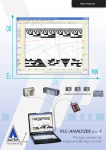
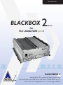
User Manual BLACKBOX 2 Rev.IV for PLC-ANALYZER pro 5 BLACKBOX 2 www.autem.de Long-term PLC process data recording and remote maintenance with PLC-ANALYZER pro 5 Mini-PC for integration in a switching cabinet User Manual BLACKBOX for PLC-ANALYZER pro 5 Copyright 1995 - 2011 AUTEM GmbH. All rights reserved. No part of this user manual, including excerpts, may be reproduced, photocopied, or electronically stored without express written permission by AUTEM. The software described in this manual is subject of a software licensing agreement and may be used only according to the terms of this agreement. AUTEM GmbH Dithmarscher Straße 29 D - 26723 Emden Germany Telephone Telefax eMail http:// +49-4921-9610-0 +49-4921-9610-96 [email protected] www.autem.de AUTEM issues no guarantee for this manual. This includes both expressly given or tacit guarantees for commercially accepted quality and suitability for a particular use. AUTEM accepts no liability for errors in the manual or for damages that may occur as a result of using or applying this material. The names of particular software and hardware products mentioned in this book are mostly registered trademarks whose usage is subject to the terms of appropriate law. We are thankful for any comments, suggestions or ideas you care to write to us. 1st Edition 2011 SIMATIC, SIMATIC-NET, S7-300, CP5611 are trademarks of Siemens AG ! ! ! ! ! WARNING Errors that can occur in the automated facility endangering humans or causing large-scale material damage must be prevented by additional external measures. These measures (e.g. independent limit monitors, mechanical interlocks) must guarantee safe operation even in the case of dangerous errors. WARNING If you use the BLACKBOX within an unprotected network you should install Windows security updates regularly. WARNING For some types of signal recording (e. g. cycle-precise acquisition) PLCANALYZER pro has to modify the PLC program. An influence of this modification on the behaviour of the PLC can not be eliminated entirely. See driver addendum of the PLC driver for further information. Caveat emptor The warranty on BLACKBOX is 12 months. The warranty no longer applies if the product is tampered with, or if the product is not handled properly, or if the product is stored under adverse conditions. The warranty also no longer applies if the device is used in a fashion that does not correspond to the manufacturer's intended use, or if used after wear-and-tear has taken effect, or if used with incorrect current or voltage, or if used after damage by surge, lightning, fire, water (dampness). The warranty no longer applies if the guaranty seal is removed or rendered unreadable. Non-warranty In no event shall AUTEM or its suppliers be liable for any damages whatsoever (including without limitation damages through loss of business profits, business interruption, loss of business information or other pecuniary loss) arising out of the use of or inability to use this AUTEM product even if AUTEM has been advised of the possibility of such damages. In any case, AUTEM´s entire liability under any provision of this agreement shall be limited to the amount actually paid for the software. This exclusion is not applicable to damages that were caused with intent or culpable negligence on sides of AUTEM. Claims also remain untouched, that are based on inalienable legal rules about product liability. Table of Contents iii Table of Contents 1 INTRODUCTION 1.1 1.2 1.3 1.4 1.5 2 Overview Field of application Performance characteristics Typical operation Help / Support INSTALLATION 2.1 2.2 2.3 3 Installation LIFE-INDICATOR for external indication of operating status Installation of additional hardware STARTING UP AND OPERATION 3.1 3.2 Operation using keyboard, mouse and screen Remote operation of BLACKBOX 3.2.1 Remote operation via LAN 3.2.2 Remote operation via Internet (VPN) 3.2.3 Remote operation using remote data transmission (via modem) 3.3 Set up the language of operating system 3.4 Watchdog 4 4.1 4.2 4.3 4.4 4.5 5 1-1 1-1 1-2 1-2 1-3 1-3 2-1 2-1 2-2 2-3 3-1 3-1 3-2 3-2 3-5 3-5 3-6 3-7 OPERATION WITH PLC-ANALYZER PRO 5 4-1 Creating the project for signal recording Start signal recording Start parameters for PLC-ANALYZER pro 5 Reading out recorded signal files Status Messages via REMOTE-STATUS-INDICATOR 4.5.1 Configure SMS dispatching 4.5.2 Configure E-mail dispatching 4-1 4-2 4-3 4-4 4-5 4-7 4-7 TROUBLESHOOTING (FAQ) 5-1 Table of Diagrams Fig. 2-1 Fig. 2-2 Fig. 2-3 Fig. 3-1 Fig. 3-2 Fig. 3-3 Fig. 3-4 Fig. 3-5 Fig. 4-1 Fig. 4-2 Fig. 4-3 Fig. 4-4 Fig. 4-5 Fig. 4-6 BLACKBOX dimensions Pinout Power Supply Floating contact jack (LIFE-INDICTOR) LAN connection via hub/switch Direct connection with LAN patch cable + crossover adapter Establish a Remote Desktop Connection Enable access to the local drives of the external PC Set up Language of Windows XP RECORDING LED Changing the PLC-ANALYZER pro 5 start parameters REMOTE-STATUS-INDICATOR - status messages Configure a status message SMS settings E-mail settings 2-1 2-2 2-2 3-2 3-2 3-3 3-4 3-6 4-2 4-4 4-5 4-5 4-7 4-7 Introduction 1-1 1 Introduction 1.1 Overview The BLACKBOX from AUTEM provides an ultra-compact data acquisition computer for the long-term recording of PLC signals and external electrical values (PLC process data archiving) and also remote maintenance using the PLC-ANALYZER pro 5. Due to its small dimensions, the system can be integrated in a switching cabinet without any problem. The BLACKBOX can continuously record and archive PLC signals over a longer period of time; typically more than 3 years1. The BLACKBOX is connected to the PLC by means supported by the PLC-ANALYZER pro 5, i.e. via connection to the PU interface or an automation network (MPI, PROFIBUS, Industrial Ethernet TCP/IP, Modbus+ …). The recording of any electrical signal outside the PLC is also possible by means of the AD_USB-Box (optional). The BLACKBOX automatically begins recording signals after being switched on and then archives the requested data. NOTE The BLACKBOX is equipped with a special version of PLC-ANALYZER pro 5. This version has special features that make an automated operation possible. These additional functions includes e. g. the automatic starting of the data acquisition, the supervision of the data acquisition by watchdog functionality, the "LIFEINDICATOR" contact for external indication of operating status or the possibility of dispatching status messages via "REMOTE-STATUS-INDICATOR". ! 1 WARNING In any case use the „LIFE-INDICATOR“ and, if necessary, also the „ REMOTESTATUS-INDICATOR “ to supervise the status of the BLACKBOX. This is the only way to recognize possible problems during data acquisition at an early stage. Depending on the number of recorded signals and signal value changes, the recording capacity may be considerably lower. Introduction 1-2 1.2 Field of application Long-term PLC process data recording Failure diagnosis Determine cause of production loss / warranty case Objective inspection of operating parameters Preventive maintenance / Condition monitoring System documentation (QA), TPM, QEE, CMS PLC Remote-Service 1.3 Performance characteristics Massive aluminium case (FANless) Fanless Mini-PC Celeron M 1.86 GHz 320 GB HDD / 2 GB RAM Dimensions (WxDxH): 195 x 268 x 80 mm / 4,4 kg Control LEDs for RECORDING, POWER, HDD, LAN Connections: PS/2 keyboard & mouse, VGA, DVI, Mic-IN, Speaker OUT, 6 x USB, 3 x RS232, 1 x RS232/RS422/485, 2 x RJ45 LAN 10/100/1000 Power supply 12 ~ 30 V DC, 40 W Ext. power adapter 100 ~ 240 V AC, 2 A, 50 ~ 60 Hz Plug with cable for ext. DC power supply Environment: Operating temperature: 5°C ~ 45°C, Relative humidity: 10 % ~ 93 % (NonCondensing) Signal recording capacity typ. 3 years Watchdog monitoring External, free floating contact (“LIFE-INDICATOR”) for external indication of operating status (plug is scope of delivery) Status messages via E-mail or SMS („REMOTE-STATUS-INDICATOR“); optional via GSM-modem Remote maintenance SW (Win9x/ 2000/XP/Vista/7) and 3 m LAN patch cable + crossover adapter for direct remote control by external PC Windows 7 Ultimate operating system (multi-lingual) Remote control via LAN, dial-up networking (modem) or internet (VPN) possible BLACKBOX-license PLC-ANALYZER pro 5 with PLC-driver Siemens SIMATIC S7 MPI/PPI/PROFIBUS cycle-precise, incl. documentation; other PLC-driver optional Siemens CP 5611 - SIMATIC-NET PROFIBUS/MPI adapter in internal PCI-slot; other PLCadapter optional (e.g. PCI85 for Modbus+) Software is completely installed, preconfigured and ready to use 48-hour burn-in, CE certificate 12 months warranty Introduction 1-3 1.4 Typical operation Create a project with PLC-ANALYZER pro 5 and save it in the BLACKBOX directory Switch off BLACKBOX Connect BLACKBOX to PLC Switch on BLACKBOX Check RECORDING-LED (flashes when signal recording is running successfully) Process data recording is running 1.5 Help / Support Should problems occur when using the BLACKBOX for the PLC-ANALYZER pro 5, please read this user manual thoroughly for assistance. Refer especially to chapter 5 Troubleshooting (FAQ). You can also find information and hints unter http://www.autem.de. Please contact our technical support if you cannot solve the problem: Technical Support AUTEM: Tel. Fax E-mail +49-(0)4921-9610-0 +49-(0)4921-9610-96 [email protected] Please have the following information at hand in addition to an exact error description: Serial number of the BLACKBOX Version and serial number of PLC-ANALYZER pro If necessary PLC model and CPU type (e.g. SIMATIC S7-300 / CPU 314) and release number Installation 2-1 2 Installation 2.1 Installation Due to the small dimensions, the BLACKBOX can be installed directly in a switching cabinet. It can be installed either horizontally or vertically. Please refer to Fig. 2-1 for the exact dimensions. The BLACKBOX should be protected against vibration and impacts. If necessary, use rubber vibration damper (part-no. ANA9055E) to protect the BLACKBOX from ambient vibration. An electric potential separation is also accomplished thereby. Fig. 2-1 BLACKBOX dimensions Installation 2-2 Connect the BLACKBOX to power supply. The BLACKBOX requires a power supply of 12 ~ 30 Volt DC, 40 watt. An appropriate DC connector is part of the material supplied. Connect [red + yellow] wire to + 12 ~ 30 V of DC. The [black + blue] wire must be connected with ground. The single anthracite colored wire is the housing screen and can be connected to ground too. Fig. 2-2 Pinout Power Supply Alternatively, the power adapter supplied can be used in order to operate the BLACKBOX with 100 ~ 240 Volt AC, 50 ~ 60 Hz. Now connect the data cable between the BLACKBOX and the PLC. NOTE The electric potential of the aluminum case of BLACKBOX is equal to electric ground of power supply. Use rubber vibration damper (part-no. ANA9055E) to achieve a potential separation between BLACKBOX and the environment. 2.2 LIFE-INDICATOR for external indication of operating status A floating contact located on the rear of the BLACKBOX provides the option of externally monitoring the operating status of the BLACKBOX. When signal recording is operating properly, the LIFE-INDICATOR contact is closed. In the case of an interruption of the recording or computer malfunctions or crashes, the contact opens. The electrical load of the contact is max. 15 W (max. switching voltage is 200 V DC.) Fig. 2-3 Floating contact jack (LIFE-INDICTOR) Installation 2-3 2.3 Installation of additional hardware Other hardware and software components may need to be connected, depending on the purpose for which the BLACKBOX is being used. Examples of this are a modem for remote maintenance, a GSM modem for dispatching of SMS- or e-mail status messages or an external DVD drive to backup signal files. Usually the BLACKBOX is supplied with the requested software configuration ready installed. Starting up and operation 3-1 3 Starting up and operation There are two methods to start up the BLACKBOX for the first time for configuration purposes. These are explained in the following sections. NOTE The BLACKBOX is equipped with a watchdog which monitors the signal recording. In case of an unforeseen interruption of the recording or a computer crash, the BLACKBOX is automatically rebooted because of the watchdog. See section 3.4 for a detailed description of the watchdog and hints for how to disable it. NOTE The BLACKBOX clock is defaultly adjusted to CET/MEZ (central european time). Check time and date during putting into operation and adjust to local time if necessary. NOTE If the BLACKBOX is installed at a place far away from your location, the remote operation (s. section 3.2 Remote operation of BLACKBOX) is a good possibility to avoid long access routes for maintenance work. By this means you can also install software updates comfortably or download signal files for analysis. 3.1 Operation using keyboard, mouse and screen Connect the keyboard, mouse and screen to the corresponding connections on the BLACKBOX. Switch on the BLACKBOX. The power-on button is located on the front panel of the BLACKBOX . Press and hold the <Ctrl> key during the entire boot routine so that the activation of the Watchdog is prevented (also refer to section 3.4). The BLACKBOX can then be operated as a normal PC running under Windows. NOTE The operation system of the BLACKBOX (Windows 7 Ultimate) is multi-lingual, i. e. the language can be changed during runtime. See section 3.3 for further infor- Starting up and operation 3-2 mation. 3.2 Remote operation of BLACKBOX 3.2.1 Remote operation via LAN For remote operation via LAN (network) connect the BLACKBOX by use of enclosed LAN patch cable directly to a network hub/switch. Fig. 3-1 LAN connection via hub/switch Alternatively establish a direct connection between BLACKBOX and external PC by use of enclosed LAN patch cable + crossover adapter. Fig. 3-2 Direct connection with LAN patch cable + crossover adapter Ensure that the corresponding LAN connection of the BLACKBOX is assigned to an IP address appropriate to your network address scheme. Starting up and operation 3-3 For remote operation of the BLACKBOX, a PC or Notebook with Win9x / NT / 2000 / XP / Vista / 7 is required. Establish a connection between the right LAN port of the BLACKBOX and a hub/switch or LAN port of the external PC. Ensure that crossover adapter must be used for a direct connection without network hub/switch. Set the IP address for the network connection of the PC to 192.168.0.2. Since the hard disk C: of the BLACKBOX is enabled in the network, access is already available to the drive (Explorer / My Network Places), e.g. to copy PLC-ANALYZER pro 5 signal or project files. If Windows XP or higher is not installed on the PC, the client for remote operation must be installed on the external PC first of all. Otherwise, skip the following instruction: The client is located on the BLACKBOX´s hard disk (c:\blackbox\client\msrdpcli.exe). Start the file and follow the instructions in order to install the client. Start the remote client. It is located under: Start / All Programs / Accessories / Remote Desktop Connection Fig. 3-3 Establish a Remote Desktop Connection Starting up and operation 3-4 Enter the Logon settings: Computer: 192.168.0.1 (IP address of the BLACKBOX) User name: Blackbox Select Local Resources / Local devices and resources / More and select the Drives checkbox. This is useful because it enables access to the local drives of the external PC during remote operation of the BLACKBOX. Fig. 3-4 Enable access to the local drives of the external PC Press the Connect button. The remote desktop connection is established. Enter the logon password: Password: Blackbox Now the BLACKBOX can be controlled by remote operation. NOTE NOTE If necessary, you can assign any other IP addresses to the LAN connections of the BLACKBOX. Write down any change made to the IP address of the right LAN connection because it is essential for establishing a connection for remote operation. More detailed information on network parameter settings in Windows is available in the Windows Help. If necessary, the user name and password of the BLACKBOX (Default: "Blackbox") can be modified under Start / Control Panel / User Accounts. Note down any changes to the settings clearly. More information is available in the Windows Help. Starting up and operation 3-5 3.2.2 Remote operation via Internet (VPN) Remote operation of the BLACKBOX can also be performed via Internet. Normally, a VPN (Virtual Private Network) is set up for this purpose. Modern Windows versions (e.g. Windows 7) are already prepared for this. Define the necessary settings under Start / Control Panel / Network and Internet (Window 7). More detailed information on network parameter settings in Windows is available in the Windows Help. 3.2.3 Remote operation using remote data transmission (via modem) Remote operation of the BLACKBOX can also be performed via a modem (DFÜ/ Rempte data transmission). To do this, a modem or an ISDN adapter must be connected to the BLACKBOX. Define the necessary settings under Start / Control Panel / Network and Internet / Network and Sharing Center (Windows 7). More detailed information on network parameter settings in Windows is available in the Windows Help. 3.2.3.1 Settings BLACKBOX Click „Change Apapter settings“ Press the <Alt> key and select “File – New incoming connection”. Select user account “Blackbox”. Next Click “Through a dial up modem” and select a modem. Next1 Open the properties of the TCP/IP-connection. Set via „Specify IP address“ the TCP/IPaddress from 192.168.0.1 to 192.168.0.10. Activate the control field „Allow calling computer to specify its own IP address“. OK. Click “Allow access” 3.2.3.2 Settings PC, which will be connected with the BLACKBOX for remote control Click “Set up a new connection or network” in the Network and Sharing Center. Select „Set up a dial-up connection“. Next Enter name for the connection (e.g. „BLACKBOX - BMW, USA“). Enter via „Dial-up phone number“ the phone number of the BLACKBOX-modem. Enter “User Name” Blackbox Click “Create”. Finish By left click on the monitor symbol in the right task bar you can choose the new connection symbol. Click “Connect“ to open the connection window. Enter user name „Blackbox“ and password „Blackbox“. Under „Connect“ the phone number of the modem should be registered already. 1 If you use an ISDN adapter choose „PPP over ISDN“ („PPP“, „PPPoE“) as DFÜ device Starting up and operation 3-6 Now press „Connect“. The connection to the BLACKBOX is established. After connection is established, open „Remote Desktop Connection“ (via „Start / All programs / Accessories “). 3.3 Set up the language of operating system The operation system of the BLACKBOX (Windows 7 ultimate) is multi-lingual, i. e. the language can be changed during runtime. Fig. 3-5 Set up Language of Windows 7 Change the language by clicking Change display language in Start / Control Panel / Clock, Language and Region. Choose the desired language under Choose a display language and confirm with OK. Log off the user „Blackbox“ (Start / Shut down / log off). After re-login the user „Blackbox“ (password: Blackbox) the menus and dialogs are displayed in the selected language. Starting up and operation 3-7 3.4 Watchdog The BLACKBOX is equipped with a watchdog which monitors the signal recording. In case of an unexpected recording interruption or a computer crash, the watchdog makes sure, that the PLC-ANALYZER pro is stopped and the BLACKBOX is automatically rebooted. Watchdog is always activated when the PLC-ANALYZER pro 5 is started with the -watchdog parameter active (setting in Startup). There are three ways in which to disable the BLACKBOX Watchdog function for maintenance work and remote operation: Hold the <Ctrl> key pressed during the boot routine (only with a keyboard which is connected directly). Manual termination of signal recording in PLC-ANALYZER pro 5. Availability of a PC for remote operation of the BLACKBOX in the network whose IP address (network address) was made known to the PLC-ANALYZER pro 5 during startup with the -cip:<ip-address> parameter (refer to section 4.3) Operations with PLC-ANALYZER pro 5 4-1 4 Operation with PLC-ANALYZER pro 5 Before beginning long-term data acquisition, the PLC-ANALYZER pro 5 must be appropriately configured. The most important steps are described, briefly, below. More information on the PLC-ANALYZER pro 5 is available in PLC-ANALYZER pro 5 User Manual. NOTE The BLACKBOX is equipped with a special version of PLC-ANALYZER pro 5. This version has special features that make an automated operation possible. 4.1 Creating the project for signal recording Start the PLC-ANALYZER pro 5 and create a project file for recording the signals. The PLCANALYZER pro 5 is configured in such a way that the signal recording defined in the project begins automatically after starting the BLACKBOX. Information on the PLC-ANALYZER pro 5 start parameters is provided in section 4.3. For reasons of data integrity, it is recommended to limit the size of the signal files created for long-term recording. We recommend a size of 60 minutes. Select Project / Project Options / Acquisition Mode and set Signalfile Size to 60 minutes. NOTE Avoid large signal files to prevent possible data loss in case of e. g. unexpected powering off the BLACKBOX during data acquisition. Small signal files have additional advantages. They can be transferred more easily during a remote session. If not specified otherwise, signal files are stored to the hard disk up to 300 MB free space. Thereafter the oldest signal files are being automatically deleted step by step (FIFO ring buffer). With –d you can specify a period of time in days, after that the oldest signal file is being deleted gradually (refer to section 4.3). Save the project on the BLACKBOX hard disk in the c:\blackbox\project folder under the name blackbox.prj. ! WARNING For some types of signal recording (e. g. cycle-precise acquisition) PLCANALYZER pro has to modify the PLC program. An influence of this modification on the behaviour of the PLC can not be eliminated entirely. See driver addendum of the PLC driver for further information. Operations with PLC-ANALYZER pro 5 4-2 4.2 Start signal recording Open c:\blackbox\project and check whether a valid project file blackbox.prj is available. Terminate the Windows session and switch the BLACKBOX off. Check that the connections to the PLC and power supply are correct. If the BLACKBOX should operate autarkic, disconnect the connections to the keyboard, mouse and screen. Switch on the BLACKBOX. The system is booted and signal recording should start, fully automatically, after about 1 minute. The red RECORDING LED (see Fig. 4-1) flashes at intervals of one second when signal recording has been started successfully. The system is now active. Signal files are subsequently recorded according to the project settings. The bottom status bar of PLC-ANALYZER pro continously displays the number of Reboots caused by watchdog, the Reconnects, the Created signal files, the Trigger and the duration of recording. The BLACKBOX enables a practically continuous recording of signals over a very long time. When the capacity has been reached, the oldest signal file is automatically deleted to create space for new signal data. Fig. 4-1 RECORDING LED NOTE NOTE If the red RECORDING LED does not start to flash at intervals of one second after 2 minutes, signal recording has not been started successfully. Also, permanent rebooting of the BLACKBOX ("Beep") indicates that signal recording has not been successfully started. We recommend to monitor the LIFE-INDICATOR (s. section 2.2) electrically e.g. by integrating it into process visualisation (HMI / SCADA). Thereby the machine operator is informed immediately about a possible interrupt in data acquisition. Operations with PLC-ANALYZER pro 5 4-3 NOTE A further means to monitor data acquisition is dispatching status messages via REMOTE-STATUS-INDICATOR. See section 4.5 for further information. 4.3 Start parameters for PLC-ANALYZER pro 5 The PLC-ANALYZER pro 5 is started automatically through an entry in the Windows Startup folder after the BLACKBOX has been booted. The syntax of the PLC-ANALYZER pro 5 start parameters is explained below: anawin [–run] [-watchdog] [-wrd:<minutes>] [-d:<days>] [-cip:<clientIP>] [<projectfile>] Example (BLACKBOX default setting): anawin -run -watchdog -wrd:10 –d:60 -cip:192.168.0.2 blackbox.prj Parameter Description -run Signal recording in the project <projectfile> is started automatically after starting the PLC-ANALYZER pro 5. -watchdog Enables the watchdog feature when the PLC-ANALYZER pro 5 is started (also refer to section 3.3). -wrd:<minutes> Delay in minutes the watchdog waits for, until the BLACKBOX is rebooted after an interruption of signal recording. If not specified, the delay time is 5 minutes. -d:<days> Specifies the size of the „ring buffer“. Signal files, which are older than the number of days specified, are being deleted. For this, PLCANALYZER pro 5 only cares for those signal files, which were created during the current session (also refer to section 4.1) -cip:<client-IP> If a PC with this IP address is available in the network on starting the PLC-ANALYZER pro, watchdog is not enabled (also refer to section 3.3). This can be helpful for maintenance purposes. <projectfile> Project file with predefined settings for recording signals. Table 4-1 PLC-ANALYZER pro 5 start parameters for BLACKBOX Operations with PLC-ANALYZER pro 5 4-4 The start parameters can be changed by opening Start / All Programs / Startup. Position the mouse on PLC-ANALYZER pro 5 and click the right mouse. The start parameters can then be modified in Properties / Shortcut / Target. Fig. 4-2 Changing the PLC-ANALYZER pro 5 start parameters 4.4 Reading out recorded signal files Signal files can be copied at any time from the c:\blackbox\project folder - even when signal recording is actually running. For more information on operation, refer to section 3. Operations with PLC-ANALYZER pro 5 4-5 4.5 Status Messages via REMOTE-STATUS-INDICATOR It is possible to monitor the operation of the BLACKBOX from a distance. Therefore the PLCANALYZER pro 5 for BLACKBOX provides the possibility of dispatching status messages via SMS or E-mail. Besides any text also some different variables (signal- and status values) can be sent. Fig. 4-3 REMOTE-STATUS-INDICATOR - status messages To create or change a status message choose REMOTE-STATUS-INDICATOR in menu Extras. The window shows all status messages defined. Inactive status messages are displayed grey. Click New in order to create a new status message. Select Change in order to change an existing one. Fig. 4-4 Configure a status message Operations with PLC-ANALYZER pro 5 4-6 Choose a meaningful Description for the message. Define whether the message should be sent as SMS or E-mail. Click on Configure to select the options for SMS or E-mail dispatching (s. 4.5.1 Configure SMS and 4.5.2 Configure E-mail ). Enter the the telephone number or the E-mail address of the Recipient of the status message. To ensure that all settings are correct, press Test in order to send the SMS or E-mail for evaluation purposes to the recipient. Adjust the Sending interval accordingly. NOTE Pay attention to the fact that high costs may incur depending on sending interval and transmission path. Enter the message in the textbox Text. Besides normal text also variables can be used. Drag the desired variable (s. Table 4-2 status variables) from the list of Variables to the textbox or use and . Variable Description <FREEDISKSPACE> Free space on current disk drive <GSMQUALITY> GSM signal strength (0 - 100 %) <LASTSIGFILE> Current signal file name <REBOOTS> Number of BLACKBOX reboots (watchdog) <RECONNECTS> Number of reconnects after acquisition interrupt <RECORDTIME> Current duration of acquisition <SIGFILES> Number of created signal files <SIGVALUE(X)> Current value of PLC signal X <SYSTIME> System time and date in the time of message dispatching <TRIGGER> Number of trigger events Table 4-2 status variables An SMS status message is limited to 160 characters. The size of an E-mail status message is not limited. After configuration of a status message, you can activate the message with check box Message active. Otherwise the configured message is only stored for now. The message can be activated anytime later. Accept the settings with OK. All active status messages are now dispatched with the specified Sending Interval. Operations with PLC-ANALYZER pro 5 4-7 4.5.1 Configure SMS dispatching Choose the device over which the SMS should be dispatched. The installation of a modem (GSM / wired) or an ISDN-CAPI (ISDN adapter) is required for that. Select the SMS Center. You can use SIM card settings or enter manually. If you coose enter manually type in the number of the SMS Center. If necessary enter the MSN number und activate Modem at an extension line, if your modem/ISDN adapter is connected to an extension line. If applicable enter also the exchange code. Confirm with OK. Fig. 4-5 SMS settings 4.5.2 Configure E-mail dispatching Choose, whether E-mails should be dispatched by installed standard mail program (e.g. Outlook) or by SMTP-Server. For dispatching by SMTP-Server you must specify, whether the connection to SMTP-Server should be established via LAN or Modem. A suitable dial-up connection is assumed. See windows help for more information on how to set up a dial-up connection. Besides SMTP-Server address enter also the forwarder e-mail address. If necessary enter a user name and a password. Click on the corresponding checkbox if the SMTP-server requires a secure connection (SSL). Confirm with OK. Fig. 4-6 E-mail settings Troubleshooting 5-1 5 Troubleshooting (FAQ) This chapter provides hints for troubleshooting the BLACKBOX. Symptom Help BLACKBOX reboots permanently Reason: The watchdog is enabled and signal recording could not be established successfully. Disable the watchdog (see 3.4 Watchdog), if you want to do maintenance work. Check the connection with the PLC, if the problem occurs during data recording. Black screen, when VGA-display is Reason: External VGA port is automatically disabled, if connected the BLACKBOX is booted without a display connected. Enable the external display by pressing <Ctrl> <Alt> F1 Table 5-1 Troubleshooting