1
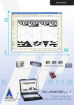
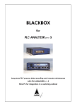
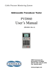
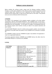
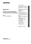
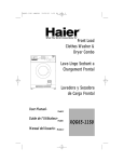
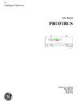
Driver-Addendum
PLC-Driver
Siemens SIMATIC S5
Industrial Ethernet TCP/IP
PLC-ANALYZER pro 5
www.autem.de
The logic analyzer for
programmable
logic controls
Driver Addendum
Siemens SIMATIC S5 - Industrial Ethernet TCP/IP
© Copyright 1995 - 2009 AUTEM GmbH. All rights reserved. No part of this user manual, including excerpts,
may be reproduced, photocopied or electronically stored without the expressive written permission of AUTEM.
The software described in this manual is subject of a software license agreement and may only be used according
to the terms of this agreement.
AUTEM GmbH
Dithmarscher Straße 29
D-26723 Emden
Germany
Telephone
Telefax
Email
Web
+49 (0)4921 9610-0
+49 (0)4921 9610-96
[email protected]
www.autem.de
AUTEM does not give any warranty for this manual as well as no express or tacit warranties on commercial quality
and suitability for a particular use. AUTEM does not take over adhesion for errors contained in it or for damages
that may occur as a result of using or applying this material.
The soft and hardware designations mentioned in this book are in most cases also registered trade marks and are
subject to the legal regulations as such.
For references, suggestions and improvement suggestions we are always grateful. Please send these to AUTEM.
1st Edition 2007
SIMATIC, SINUMERIK, SIMOTION, S5, S7, C7, M7, STEP5, STEP7, S7-200, S7-300, S7-400, and S7-PLCSIM are registered trademarks of Siemens AG
Table of contents
iii
Table of Contents
1
INSTALLATION
1.1
Installation of PLC driver
1.1.1 Installing additional hardware
1.1.2 Installing additional software
1.2 Configuration of PLC driver
1.3 Configuring of CP for data acquisition
1.3.1 Initialization of Siemens CP1430 TCP
1.3.2 Create a transport connection
1.3.2.1 Create an RFC1006-connection
1.3.2.2 Create a TCP-connection
2
DATA ACQUISITION
2.1
2.2
2.3
2.4
Supported PLC models and CPUs
Recordable PLC addresses
Number of simultaneously recordable addresses
Time behavior and particularities
1-1
1-1
1-1
1-1
1-2
1-3
1-3
1-4
1-4
1-5
2-1
2-1
2-1
2-2
2-2
Table of Figures
Fig. 1-1
Fig. 1-3
Fig. 1-4
Fig. 1-5
Fig. 1-6
Fig. 1-7
Driver settings (SIMATIC S5)
Initialization of CP1430
Create an RFC1006-connection - job type "Fetch"
Create an RFC1006-transport connection - job type "Receive"
Create a TCP-connection - job type “Fetch”
Create a TCP-connection - job type "Receive"
1-2
1-4
1-4
1-5
1-5
1-6
List of Tables
Table 2-1 Address syntax SIMATIC S5
Table 2-2 Scan times on SIMATIC S5-135U
2-2
2-3
Installation
1
1-1
Installation
This driver addendum describes the particularities of the following PLC driver and gives you
hints on the usage:
• Siemens SIMATIC S5 - Industrial Ethernet TCP/IP
The listed driver makes the acquisition of PLC signals through Industrial Ethernet (TCP/IP)
possible.
It is important, that you read through the driver addendum first, before you use a PLC driver.
Please pay attention to the WARNINGS that advise you on possible dangers when using PLCANALYZER pro.
!
1.1
WARNING
Errors that may occur in the automated facility endangering humans or causing
large-scale material damage must be prevented by additional external precautions.
These precautions (e.g. independent limit monitors, mechanical interlocks) must
guarantee a safe operation even in the case of dangerous errors.
Installation of PLC driver
The PLC driver can be installed while PLC-ANALYZER pro is operating. Select PLC driver in
the menu Extras. In the window PLC driver click the button Add. If the desired driver is not on
the list, you have to install a new driver via the License-key management (s. user manual PLCANALYZER pro 5 - chapter 2-2 Installation).
With PLC-ANALYZER pro you can load the same or different PLC drivers more than once.
You can, for example, acquire simultaneously signal data from two SIMATIC S5, which are
connected to two different COM ports of the PC.
1.1.1 Installing additional hardware
If you have already connected your programming unit (or your PC) with the automation device
via Ethernet TCP/IP network, usually nothing else must be done.
For connecting you PC to a TCP/IP Ethernet network, a normal network card can be used. The
PLC must be equipped with a suitable communication processor (CP). Siemens CP1430 TCP,
VIPA CP143 TCP/IP and INAT S5-TCP/IP are supported.
1.1.2 Installing additional software
In addition to the PLC-ANALYZER pro basic module and the PLC driver no other software is
necessary.
Installation
1-2
1.2
Configuration of PLC driver
After installing the driver you can change important parameters under Properties. If you have
loaded several drivers, you can set the properties for each driver individually.
Fig. 1-1 Driver settings (SIMATIC S5)
Choose a Name for the driver first, than specify under Connection the IP-Address of PLC. The
IP-Address must be identical to the IP-Address used for initialization of the communication
processor (Siemens CP1430 TCP, VIPA CP143 TCP/IP or INAT S5 TCP/IP).
Use Time stamp to specify, if the time stamps should be entered into the signal file continually
(at every scan point) or only for signal changes. For a continuous time stamp the exact scan
points are documented even for a signal which does not change. The signal files are therefore
larger.
Under Scan interval enter the length of time between read-out of data from the PLC. A longer
scan interval may be chosen for non-critical time signals, e.g. temperature. The signal files thus
created become smaller.
Under Symbolism you can assign a symbol file to the loaded driver. This makes the use of a
symbolic identifier for the address definition possible (s. user manual PLC-ANALYZER pro 5 chapter 4.1 Address selection). Besides the absolute addresses, the symbolic identifier and the
comments will be shown and stored in a signal- or project-file.
Installation
1-3
Select the used transport connection.
Use Settings to specify the parameter for
the selected connection. Use exactly the
same parameter, which were used for the
parameterized transport connections of
the CP1430 (s. 1.3 Configuring of CP
for data acquisition)
Fig. 1-2 Properties of transport connections
1.3
Configuring of CP for data acquisition
The SIMATIC S5 PLC has to be equipped with a communication processor (CP) for data acquisition with PLC-ANALYZER via TCP/IP. Siemens CP1430 TCP, VIPA CP143 and INAT S5TCP/IP are supported. The configuration of Siemens CP1430 TCP is exemplary described below. The configuration of the other CPs is similiar. Refer to the user manual of the CP for further information.
1.3.1 Initialization of Siemens CP1430 TCP
The CP1430 is parameterized with Siemens STEP 5 configuration software “COM1430
TCP/IP”. Go to “COM1430 TCP/IP” in STEP 5 if you want to configure CP1430 TCP or determine the settings.
Installation
1-4
Fig. 1-3 Initialization of CP1430
Choose CP Init in menu Edit to determine the IP address of the CP. You can select an IP address here, if you did not already configure the CP. All settings must be transferred to the CP by
choosing FD -> CP in menu Transfer.
1.3.2 Create a transport connection
Two transport connections with job type “Fetch” and “Receive” are necessary for data connection between PC and CP1430. These connections can be either of type RFC1006 (ISO on TCP)
or TCP.
1.3.2.1
Create an RFC1006-connection
To create an RFC1006-connection choose Connections - Transport Conn. (RFC1006) in menu
Edit.
Fig. 1-4 Create an RFC1006-connection - job type "Fetch"
Choose “Fetch” as job type. Enter a unique TSAP 1 under Transport addresses for the local and
remote site.
1
TSAP = Transport Service Access Point
Installation
Fig. 1-5 Create an RFC1006-transport connection - job type "Receive"
Create another RFC1006-connection with job type “Receive”. Enter unique TSAPs here too.
1.3.2.2
Create a TCP-connection
To create a TCP-connection choose Connections - Transport Conn. (TCP) in menu Edit.
Fig. 1-6 Create a TCP-connection - job type “Fetch”
Choose “Fetch” as job type. Enter an unambiguous port number for the local site.
1-5
1-6
Installation
Fig. 1-7 Create a TCP-connection - job type "Receive"
Create another TCP-connection with job type “Receive”. Enter an unambiguous port number
here too.
Data acquisition
2
Data acquisition
2.1
Supported PLC models and CPUs
2-1
The following models of SIMATIC S5 family are supported by this PLC driver driver:
• Siemens SIMATIC S5-115U
• Siemens SIMATIC S5-135U
• Siemens SIMATIC S5-155U
A communication processor (CP) is required to record data through a TCP/IP network. The following CPs are supported by this PLC driver:
• Siemens CP1430 TCP
• VIPA CP143 TCP/IP
• INAT S5-TCP/IP
2.2
Recordable PLC addresses
The following table shows the recordable addresses and the corresponding address syntax:
Syntax
Address type
Example
Qx.z
QBx
QWx
QDx
Ix.z
IBx
IWx
IDx
Fx.z
FBx
FWx
FDx
PWx
Tx
Cx
yDLx
Output byte x, bit z
Output byte x
Output word x
Output double word x
Input byte x, bit z
Input byte x
Input word x
Input double word x
Flag byte x, bit z
Flag byte x
Flag word x
Flag double word x
I/O word x (only input)
Timer x
Counter x
Left data byte x from DB y
Q32.4
QB9
QW14
QD98
I17.0
IB127
IW12
ID124
F3.7
FB250
FW24
FD134
PW214
T2
C5
20DL15
Data acquisition
2-2
Syntax
Address type
Example
yDRx
yDWx
yDDx
yDXx
Right data byte x from DB y
Data word x from data block y
Data double word x from DB y
Data word x from DX-module y
21DR53
12DW5
27DD0
22DX15
Table 2-1 Address syntax SIMATIC S5
2.3
NOTE
The automation devices of the SIMATIC S5 family allow only byte-oriented data
acquisition. PLC-ANALYZER pro automatically converts a given bit address to a
byte address. All bits are available for display.
Number of simultaneously recordable addresses
Up to 1000 addresses can be recorded simultaneously. The term “address” means a byteaddress. The recording of a word- or double-word-address results in capturing of 2 or 4 bytes,
respectively. So 500 word-addresses or 250 double-word-addresses can be recorded.
2.4
Time behavior and particularities
NOTE
Acquiring data with PLC-ANALYZER pro results in a small increase in cycle
time in the automation device to the same manner as it happens with STEP5 in the
operating mode STAT VAR.
The intervals between scan transfers from the SIMATIC PLC to the computer are depending on
the following items:
• CPU type
• cycle time of PLC
• Number and combination of recorded addresses. Blocks for transfer are created. Every
block requires additional time.
For the SIMATIC S5-135U (CPU928) the scan interval for a byte is approximately 30 ms, i.e.
for a cycle time > 30 ms there is one scan for each cycle. For a longer PLC cycle time data
transfer is synchronized with the PLC cycle.
Data acquisition
2-3
For a shorter cycle time the computer does not obtain a scan for each cycle, resulting in a partial
loss of information. This loss can be compensated by repeated measurements of the interesting
signals.
Every additional requested byte of the same type leads to an insignificant increase of scan time
only (s. Table 2-2 Scan times on SIMATIC S5-135U). Every new address type leads to an increase of scan time of ≈ 30 ms.
The following table exemplarily shows some values of time behaviour during acquisition:
Requested data
Scan time
1 flag byte
50 flag words
100 flag words
1 flag byte, 1 output byte
50 flag byte, 50 data words
10 flag words, 10 data words, 10 inputs, 10 outputs
30 ms
32 ms
33 ms
61 ms
64 ms
127 ms
Table 2-2 Scan times on SIMATIC S5-135U