1
Installation
HSM18HEKC/HRAC03/R2(DB) HUM18HC03/R2(DB) -SM
8 Installation
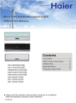
Installation Manual of Room Air Conditioner
Preparation
Necessary Tools for Installation
ƽ
ƽ
ƽ
ƽ
ƽ
ƽ
Selection of Installation Place
ƽ Torque wrench
(17mm,22mm,26mm)
ƽ Pipe cutter
ƽ Flaring tool
ƽ Knife
ƽ Measuring tape
ƽ Reamer
Driver
Nipper
Hacksaw
Hole core drill
Spanner(17,19 and 26mm)
Gas leakage detector or
soap-and-water solution
Indoor Unit
ƽ Place, robust not causing vibration, where the body can be supported sufficiently.
ƽ Place, not affected by heat or steam generated in the vicinity, where inlet and outlet of the
unit are not disturbed.
ƽ Place, possible to drain easily, where piping can be connected with the outdoor unit.
ƽ Place, where cold air can be spread in a room entirely.
ƽ Place, nearby a power receptacle, with enough space around. (Refer to drawings).
ƽ Place where the distance of more than lm from televisions, radios, wireless apparatuses
and fluorescent lamps can be left.
Power Source
ƽ In the case of fixing the remote controller on a wall, place where the indoor unit can
receive signals when the fluorescent lamps in the room are lightened.
ƽ Before inserting power plug into receptacle, check the voltage without fail.
The power source is the same as the corresponding name plate.
ƽ Install an exclusive branch circuit of the power.
ƽ A receptacle shall be set up in a distance where the power cable can be
reached.Do not extend the cable by cutting it.
Outdoor Unit
ƽ Place, which is less affected by rain or direct sunlight and is sufficiently ventilated.
ƽ Place, possible to bear the unit, where vibration and noise are not increased.
ƽ Place, where discharged wind and noise do not cause a nuisance to the neighbors.
ƽ Place, where a distance marked is available as illustrated in the above figure.
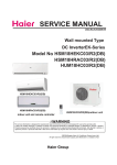
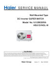
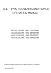
Drawing for the installation of indoor and outdoor units
The models adopt HFC free refrigerant R410A
Attention must be paid to
the rising up of drain hose
more than 5cm
Optional parts for piping
A Non-adhesive tape
B Adhesive tape
C Saddle (L.S) with screws
Connecting electric cable
for indoor and outdoor
E Drain hose
F Heating insulating material
G
more than
10cm
D
G Piping hole cover
Arrangement of piping
directions
more than 10cm
F
Rear left
Floor fixing dimensions of the
A
Rear
right
Left
outdoor unit (Unit:mm)
Right
C
Below
more than 10cm
more than
10cm
Fixing of outdoor unit
ƽ Fix the unit to concrete or block
ƽ The marks from A to
G in the figure are the
parts numbers.
ƽ The distance between
the indoor unit and the
floor should be more
than 2m.
with bolts (10mm) and nuts firmly
and horizontally.
ƽ When fitting the unit to wall
surface, roof or rooftop, fix
D
a supporter surely with nails
or wires in consideration of
E
earthquake and strong wind.
ƽ If vibration may affect the
more than
60cm
house, fix the unit by attaching a
vibration-proof mat.
more than15cm
Please be subject to the actual product purchased , the above picture is just for your reference.
Read this manual before installation
Explain sufficiently the operating means to the user according to this manual.
NO.0010531116
68
Domestic air conditioner
Installation
HSM18HEKC/HRAC03/R2(DB) HUM18HC03/R2(DB) -SM
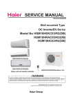
1. Insert the drain hose into the dent of heat insulation materials of indoor unit.
2. Insert the indoor/outdoor electric cable from backside of indoor unit, and pull it
out on the front side, then connect them.
3. Coat the flaring seal face with refrigerant oil and connect pipes.
Cover the connection part with heat insulation materials closely, and make sure
fixing with adhesive tape
Accessory parts
Remote controller (1)
Drain hose (1)
R-03 dry battery (2)
Cushion (4)
Mounting plate (1)
Drain-elbow (1)
Indoor/outdoor electric cable
Plastic cap (4)
Ø4X25 Screw (4)
Heat insulation
material
Lid for right
piping
Pipe supporting plate (1)
Lid for left piping
Piping
Pipe supporting
plate
Drain hose
Lid for under piping pipe
Selection of pipe
Fix with adhesive tape
Liquid pipe (Ø)
6.35mm(1/4”)
Gas pipe (Ø)
12.7mm(1/2”)
● Indoor/outdoor electric cable and drain hose must be bound with refrigerant
piping by protecting tape.
[ Other direction piping ]
● Cut away, with a nipper, the lid for piping according to the piping direction and
then bend the pipe according to theposition of wall hole. When bending, be
careful not to crash pipes.
● Connect beforehand the indoor/outdoor electric cable, and then pull out the
connected to the heat insulation of connecting part specially.
NOTE˖The thickness of the pipe must be 0.8mm at least.
Indoor unit
1
Fitting of the Mounting Plate and Positioning of the wall Hole
Fixing the indoor unit body
When the mounting plate is first fixed
1. Carry out, based on the neighboring pillars or lintels, a proper leveling for the plate
to be fixed against the wall, then temporarily fasten the plate with one steel nail.
2. Make sure once more the proper level of the plate, by hanging a thread with a
weight from the central top of the plate, then fasten securely the plate with the
attachment steel nail.
3. Find the wall hole location A using a measuring tape
●
Hang surely the unit body onto the upper notches of the
mounting plate. Move the body from side to side to verify its
secure fixing.
●
In order to fix the body onto the mounting plate,hold up
the body aslant from the underside and then put it down
perpendicularly.
Unloading of indoor unit body
B= 60mm
●
When you unload the indoor unit,please use
your hand to arise the body to leave agraffe,
then lift the bottom of the body outward
slightly and lift the unit aslant until it
leaves the mounting plate.
30mm
A=145mm
mounting plate
B= 60mm
4
30mm
A=150mm
agraffe
mounting plate
Connecting the indoor/outdoor Electric Cable
Removing the wiring cover
When the mounting plate is fixed side bar and lintel
● Fix to side bar and lintel a mounting bar, Which is separately sold, and then
fasten the plate to the fixed mounting bar.
●
Remove terminal cover at right bottom corner of indoor unit, then take
off wiring cover by removing its screws.
● Refer to the previous article, “ When the mounting plate is first fixed “, for the
position of wall hole.
2
When connecting the cable after installing the indoor unit
Making a Hole on the Wall and Fitting the Piping Hole Cover
● Make a hole of 60 mm in diameter, slightly descending to outside the wall.
● Install piping hole cover and seal it off with putty after installation
Wall hole
1. Insert from outside the room cable into left side of the wall
hole, in which the pipe has already existed.
2. Pull out the cable on the front side, and connect the cable
making a loop.
Ø60mm
When connecting the cable before installing the indoor unit
Indoor side
(Section of wall hole)
3
●
●
Outdoor side
Thickness of wall
G Piping hole pipe
●
Installation of the Indoor Unit
●
Drawing of pipe
Insert the cable from the back side of the unit, then pull it out on the front side.
Loosen the screws and insert the cable ends fully into terminal block, then
tighten the screws.
Pull the cable slightly to make sure the cables have been properly inserted and
tightened.
After the cable connection, never fail to fasten the connected cable with the
wiring cover.
[ Rear piping ]
● Draw pipes and the drain hose, then fasten them with the adhesive tape
[ Left· Left-rear piping ]
● In case of left side piping, cut away, with a nipper, the lid for left piping.
● In case of left-rear piping, bend the pipes according to the piping direction to
the mark of hole for left-rear piping which is marked on heat insulation materials.
Note
When connecting the cable, confirm the terminal number of indoor and
outdoor units carefully. If wiring is not correct, proper operation can not
be carried out and will cause defect.
69
Domestic air conditioner
Installation
HSM18HEKC/HRAC03/R2(DB) HUM18HC03/R2(DB) -SM
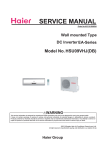
Outdoor unit
Outdoor unit A
1(N) 2 (L) 3 (C)
4G0.75mm2
Installation of Outdoor Unit
POWER
HUM18HA03/R2(DB)
HUM18HB03/R2(DB)
Power cable:
1(N ) 2 (L) 3 (C )
Indoor unit A
^
Drawing for the installation of indoor and outdoor units
Install according to
Connection of pipes
ƽ To bend a pipe, give the roundness as large as possible not to crush the pipe ,
and the bending radius should be 30 to 40 mm or longer.
ƽ Connecting the pipe of gas side first makes working easier.
ƽ The connection pipe is specialized for R410A.
Half union
Forced fastening without careful centering may
damage the threads and cause a leakage of gas.
Flare nut
Pipe Diameter(ǿ)
3G2.5mm2
Spanner
Outdoor unit A
Fastening torque
Liquid side6.35mm(1/4")
18N.m
Liquid/Gas side9.52mm(3/8")
42 N.m
Gas side 12.7mm(1/2")
55N.m
Gas side 15.88mm(5/8")
60 N.m
Torque wrench
1
2
Be careful that matters, such as wastes of sands, etc. shall not enter the pipe.
The standard pipe length is 5m. If it is overm, the function of the unit will be
affected. If the pipe has to be lengthened, the refrigerant should be charged,
according to 20 g/m. But the charge of refrigerant must be conducted by professional air conditioner engineer. Before adding additional refrigerant, perform air
purging from the refrigerant pipes and indoor unit using a vacuum pump,then
charge additional refrigerant.
3(C)
4G0.75mm2
HUM18HC03/R2(DB)-EU
Power cable:
( )
^
CAUTION
Outdoor unit
( )
2N
POWER
1L
Indoor unit A
Indoor unit
B
B
A
A
Indoor unit
Outdoor unit
3G2.5mm2
●
●
Outdoor unit
Indoor unit
B
Oil trap
Indoor unit
L
A
N
Outdoor unit
●
●
Max.Elevation: Amax=15m
In case the elevation A is more
than 5m, oil trap shoud be
installed every 5~7m
Max. Length: Bmax=25m
In case the pipe length B is
more than 10m, the refrigerant
should be charged, according
to 20 g/m.
1
2
4G0.75mm
3(C)
2
Connection
ƽ Use the same method on indoor unit. Loosen the screws on
ƽ
( )
ƽ
( )
{
ƽ
2N
POWER
1L
1(N)
2(L)
3
HFM18HC03/R2(DB)
Power cable:
HUM18HC03/R2(DB)-EU
terminal block and
insert the plugs fully into terminal block, then tighten the screws.
Insert the cable according to terminal number in the same manner as the indoor
unit.
If wiring is not correct, proper operation can not be carried out and controller
may be damaged.
Fix the cable with a clamp.
Attaching Drain-Elbow
ƽ If the drain-elbow is used,
please attach it as figure. (Note:
Only for heat pump unit.)
3G2.5mm2
1. If the supply cord is damaged, it must be replaced by the manufacturer or its
service agent or a similar qualified person. The type of connecting wire is
Purging Method:To use vacuum pump
1.
H05RN-F or H07RN-F.
2. If the fuse on PC board is broken please change it with the type of
T. 3.15A/250V.
Detach the service port’s cap of 3-way valve, the valve rod’s cap for 2-way valve
and 3-way’s, connect the service port into the projection of charge hose (Iow)
for gaugemanifold. Then connect the projection of charge hose (center) for gaugemanifold into vacuum pump.
2. Open the handle at Iow in
gaugemanifold, operate vacuum pump. If the scalemoves of gause (Iow) reach vacuum condition in a moment, check 1. again.
3. The wiring method should be in line with the local wiring standard.
4. After installation, the power plug should be easily reached.
5. A breaker should be incorporated into fixed wiring. The breaker should be
all-pole switch and the distance between its two contacts should be not less
than 3mm.
3. Vacuumize for over 15min.And check the level gauge which should read -0.1MPa
(76 cm Hg) at Iow pressure side. After the completion of vacuumizing, close the
handle ‘Lo’ in gaugemanifold and stop the operation of the vacuum pump. Check
condition of the scale and hold it for 1-2min. If the scale-moves back in spite of
tightening, make flaring work again, the return to the beginning of 3 .
4. Open the valve rod for the 2-way valve to an angle of anticlockwise 90 degrees.
After 6 seconds, close the 2-way valve and make the inspection of gas leakage.
70
Domestic air conditioner
Installation
HSM18HEKC/HRAC03/R2(DB) HUM18HC03/R2(DB) -SM
5. No gas leakage?
In case of gas leakage, tighten parts of pipe connection. If
leakage stops, then proceed 6. steps
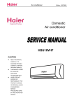
On Drainage
ƽ Please install the drain hose so as to be downward slope without fail.
ƽ Please don’t do the drainage as shown below.
If it does not stop gas leakage, discharge whole refrigerants from the service
port. After flaring work again and vacuumize, fill up prescribed
refrigerant from the gas cylinder.
Less than
5cm
6. Detach the charge hose from the service port, open 2-way valve and 3-way. Turn
the valve rod anticlockwise until hitting lightly.
leakage, turn the service port’s cap, the valve rod’s cap for 2-way
valve and 3-way’s a little more than the point where the torque increases suddenly.
7.To prevent the gas
8. After attaching the each caps, check the gas
It becomes The end is imm- It waves. The gap with the
There is the bad
high midway. ersed in water.
ground is too small. smell from a ditch
ƽ Please pour water in the drain pan of the indoor unit, and confirm that drainage
leakage around the caps.
is carried out surely to outdoor.
ƽ In case that the attached drain hose is in a room, please
apply heat insulation to
it without fail.
Step 1.
Step 2.
2-way valve Liquid Side
3-way valve Gas Side
Open
Ƶ Refrigerant charge label
Gaugemanifold(for R410A)
Anti countercurrent joint
Contains fluorinated greenhouse gases
covered by the Kyoto Protocol
Step 3.
Close
Tube(for R410A)
Step 4.
Vacuum pump(for R410A)
Step 6.
2-way valve
R410A
1=
kg
2
2=
kg
1+2=
kg
1
2-way valve
3-way valve
3-way valve
O
Open 90
F
2-way valve
3-way valve
Step 7.
Valve rod cap
Valve rod cap
Service port cap
CAUTION
ƽ If the refrigerant of the air conditioner leaks, it is necessary to discharge all the
refrigerant. Vacuumize first, then charge the liquid refrigerant into air conditioner according to the amount marked on the name plate.
ƽ Please do not let other cooling medium, except specified one (R410A), or air
enter into the cooling circulation system. Otherwise, there will be abnormal
high pressure in the system to make it crack and lead to personal injuries.
Power Source Installation
ƽ The power source must be exclusively used for air conditioner. (Over I0A)
ƽ In the case of installing an air conditioner in a moist place, please install an earth leakage breaker.
ƽ For installation in other places, use a circuit breaker as far as possible.
Check Items for Test Run
Conventional flare tool
Clutch-type
clutch-type(Rigid-type) Wing-nut type (Imperial-type)
1.0~1.5mm
1.Cut pipe
Flare tooling die
3.Insert the flare nut
Correct
D
E
Ƶ Please kindly explain to our customers how to operate
through the instruction manual.
be removed.
Flare tool for R410A
0~0.5mm
C
Ƶ Check for Installation and Test Run
Cutting and Flaring Work of Piping
ƽ Pipe cutting is carried out with a pipe cutter and burs must
ƽ After inserting the flare nut, flaring work is carried out.
A
B
This product contains fluorinated greenhouse gases covered by
the Kyoto Protocol. Do not vent into the atmosphere.
Refrigerant type:R410A
GWP* value:1975
GWP=global warming potential
Please fill in with indelible ink,
•1
the factory refrigerant charge of the product
•2
the additional refrigerant amount charged in the field and
• 1+2 the total refrigerant charge
on the refrigerant charge label supplied with the product.
The filled out label must be adhered in the proximity of the product
charging port (e.g. onto the inside of the stop value cover).
A contains fluorinated greenhouse gases covered by the Kyoto
Protocol
B factory refrigerant charge of the product: see unit name plate
C additional refrigerant amount charged in the field
D total refrigerant charge
E outdoor unit
F refrigerant cylinder and manifold for charging
2-way valve 3-way valve
A
Put check mark
in boxes
Gas leak from pipe connecting?
Heat insulation of pipe connecting?
Are the connecting wirings of indoor and outdoor firmly
inserted to the terminal block?
Is the connecting wiring of indoor and outdoor firmly fixed?
Is drainage securely carried out?
Is the earth line securely connected?
Is the indoor unit securely fixed?
Is power source voltage abided by the code?
Is there any noise?
Is the lamp normally lighting?
Are cooling and heating (when in heat pump) performed normally?
Is the operation of room temperature regulator normal?
1.5~2.0mm
2.Remove burs
4.Flare pipe
Incorrect
Lean
Damage of flare Crack
Partial
Too outside
Domestic air conditioner
HSM18HEKC/HRAC03/R2(DB) HUM18HC03/R2(DB) -SM
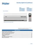
Removal of indoorunit (HSM18HEKC03/R2(DB))
72
Removal Procedure
HSM18HEKC/HRAC03/R2(DB) HUM18HC03/R2(DB)-SM
73
HSM18HEKC/HRAC03/R2(DB) HUM18HC03/R2(DB)-SM
Removal Procedure
Open the front panel
until it is on the
horizontal position,
and then release the
pivots on both sides of
the unit to remove the
front panel.
Please close the panels
before start the removal
procedure of front grille.
Slide the front panel from
one side to another to
release each axis.
74
HSM18HEKC/HRAC03/R2(DB) HUM18HC03/R2(DB)-SM
two
HOOKS
three
75
Removal Procedure
HSM18HEKC/HRAC03/R2(DB) HUM18HC03/R2(DB)-SM
Removal Procedure
flap
flap
flap
flap
76
HSM18HEKC/HRAC03/R2(DB) HUM18HC03/R2(DB)-SM
77
Removal Procedure
HSM18HEKC/HRAC03/R2(DB) HUM18HC03/R2(DB)-SM
78
Removal Procedure
HSM18HEKC/HRAC03/R2(DB) HUM18HC03/R2(DB)-SM
79
Removal Procedure
HSM18HEKC/HRAC03/R2(DB) HUM18HC03/R2(DB)-SM
80
Removal Procedure
HSM18HEKC/HRAC03/R2(DB) HUM18HC03/R2(DB)-SM
81
Removal Procedure
HSM18HEKC/HRAC03/R2(DB) HUM18HC03/R2(DB)-SM
82
Removal Procedure
HSM18HEKC/HRAC03/R2(DB) HUM18HC03/R2(DB)-SM
83
Removal Procedure
HSU-18HEKC/HRAC03/R2(DB)HUM18HC03/R2(DB)-SM
Removal Procedure
9.2 The removal procedure of Indoor unit HSM18HRAC03/R2(DB)
9.2.1 Removal of Front Panel
Procedure
Step
1. Features
Procedure
Points
2. Remove the front panel
1
Hold the front
panel by the tabs
on the both sides
and lift it until it
2
Open the front
panel to the
and left axes with
Release the
both sides pivots
and insert them
and remove the
to the end.
front panel.
84
Domestic Air Conditioner
HSU-18HEKC/HRAC03/R2(DB)HUM18HC03/R2(DB)-SM
Step
3
Pull the front panel
RXWKRUL]RQWDOO\
Procedure
Removal Procedure
Points
and remove it.
85
Domestic Air Conditioner
HSU-18HEKC/HRAC03/R2(DB)HUM18HC03/R2(DB)-SM
Removal Procedure
9.2.2 Removal of Air Filter
Step
Procedure
/LIWDQDLU¿OWHU
XSZDUGVVOLJKWO\
and then pull it
out downwards.
Points
Insert the air
¿OWHUVDORQJJURRYHV
ZKHQLQVWDOOLQJ
:KHQLQVWDOOLQJ
LQVHUWKRRNVRIWKH
DLU¿OWHUFRPSOHWHO\
86
Domestic Air Conditioner
HSU-18HEKC/HRAC03/R2(DB)HUM18HC03/R2(DB)-SM
Removal Procedure
9.2.3 Removal of the blade
Step
Procedure
Release the
PDUNHGKRRNV
Pull out and
remove the blade.
Points
Insert the air
¿OWHUVDORQJJURRYHV
ZKHQLQVWDOOLQJ
:KHQLQVWDOOLQJ
LQVHUWKRRNVRIWKH
DLU¿OWHUFRPSOHWHO\
87
Domestic Air Conditioner
HSU-18HEKC/HRAC03/R2(DB)HUM18HC03/R2(DB)-SM
Removal Procedure
9.2.4 Removal of Front Case
Step
1
2
Procedure
Points
Release the
screw covers
Loosen the 2
¿[LQJVFUHZV
88
Domestic Air Conditioner
HSU-18HEKC/HRAC03/R2(DB)HUM18HC03/R2(DB)-SM
Step
3
4
Procedure
Removal Procedure
Points
Loosen the
PDUNHGKRRNV
Pull out the
front case.
89
Domestic Air Conditioner
HSU-18HEKC/HRAC03/R2(DB)HUM18HC03/R2(DB)-SM
Removal Procedure
9.2.5 Removal of Vertical Blades and Display Board
Step
1
Procedure
Points
Pull out the
Vertical Blades.
/RRVHQWKH¿[LQJ
2
screws,and remove
the display board.
Loosen the screw of
3
the drip proof plate.
Lift and remove
the electrical box.
90
Domestic Air Conditioner
HSU-18HEKC/HRAC03/R2(DB)HUM18HC03/R2(DB)-SM
Removal Procedure
9.2.6 Removal of Fan Drain pan and Electrical Box
Step
1
2
Procedure
Points
Loosen the
2 screws.
Pull out the
drain pan.
'LVFKDUJHWKH
static electricity
3
Loosen the screw of
from your body
the drip proof plate.
EHIRUHWRXFKLQJWKH
HOHFWULFDOSDUWVOLNH
Lift and remove
VLJQDOUHFHLYHU3&%
It may cause the
the electrical box.
malfunction of PCB.
91
Domestic Air Conditioner
HSU-18HEKC/HRAC03/R2(DB)HUM18HC03/R2(DB)-SM
Removal Procedure
25HPRYDORI)DQ0RWRUDQG+HDW([FKDQJHU
Step
1. Remove the
ULJKWVLGHSODWH
1
Loosen the
Procedure
Points
2 screws.
2
Remove the
¿[LQJSODWH
3
Lift up the
evaporator
Be careful not to
FXW\RXU¿QJHU
E\WKH¿QVRIWKH
evaporator.
3. Remove the fan.
1
Loosen the
2 screws.
92
Domestic Air Conditioner
HSU-18HEKC/HRAC03/R2(DB)HUM18HC03/R2(DB)-SM
Step
2
/LIWXSWKHULJKW
part of the fan
Procedure
Removal Procedure
Points
motor and slide it
WRWKHULJKWZDUGWR
remove.
3
/LIWXSWKHULJKW
part of the fan
and remove it
93
Domestic Air Conditioner
HSM18HEKC/HRAC03/R2(DB) HUM18HC03/R2(DB)-SM
Removal of procedure
9.3 The removal procedure of outdoor
9.3.1 Removal of Outdoor panel
Step
1. Features
1
Loosen the service
Procedure
Points
Be careful not to
FXW\RXU¿QJHUE\
cover screw and
remove the service
cover.
WKH¿QVRIWKHKHDW
H[FKDQJHU
94
Domestic air conditioner
HSM18HEKC/HRAC03/R2(DB) HUM18HC03/R2(DB)-SM
Step
2. Remove the panels.
1
Loosen the 4 screws
and lift the top panel
2
Loosen the screws
of the panel.
3
Pull and remove
the front panel.
Procedure
Removal of procedure
Points
95
Domestic air conditioner
HSM18HEKC/HRAC03/R2(DB) HUM18HC03/R2(DB)-SM
Removal of procedure
9.3.2 Romoval of Electrcal Box
Step
Procedure
Points
5HPRYHWKH¿[LQJ
screws, then lift
the electrical box
*
*
*
*
*
*
*
96
Domestic air conditioner
HSM18HEKC/HRAC03/R2(DB) HUM18HC03/R2(DB)-SM
Removal of procedure
9.3.3 Romoval of the Side panel
Step
Procedure
Points
/RRVHQWKH¿[LQJ
1
screws and remove
the side panel.
97
Domestic air conditioner
HSM18HEKC/HRAC03/R2(DB) HUM18HC03/R2(DB)-SM
Step
Procedure
2
Remove the
EDFNSDQHO
3
/RRVHQWKH¿[LQJ
screws and remove
the side panel.
Removal of procedure
Points
98
Domestic air conditioner
HSM18HEKC/HRAC03/R2(DB) HUM18HC03/R2(DB)-SM Removal of procedure
9.3.4 Removal of fan and fan motor
Step
Procedure
Points
Put the lead wire
Loosen the
of motor when
1
remove the fan
the propeller fan)
99
Domestic air conditioner
HSM18HEKC/HRAC03/R2(DB) HUM18HC03/R2(DB)-SM Removal of procedure
Step
2
Procedure
Points
screws and lift
the fan motor.
100
Domestic air conditioner
HSM18HEKC/HRAC03/R2(DB) HUM18HC03/R2(DB)-SM
Step
3
Procedure
Removal of procedure
Points
screws, then lift the
101
Domestic air conditioner
HSM18HEKC/HRAC03/R2(DB) HUM18HC03/R2(DB)-SM
Step
4
Procedure
Removal of procedure
Points
screws, then lift
the proof plate.
102
Domestic air conditioner
HSM18HEKC/HRAC03/R2(DB) HUM18HC03/R2(DB)-SM
Step
Procedure
Removal of procedure
Points
Cut down the
1
and pull out the
compressor
and remove the
103
Domestic air conditioner
HSM18HEKC/HRAC03/R2(DB) HUM18HC03/R2(DB)-SM
Step
Procedure
Removal of procedure
Points
2
4
Domestic air conditioner
HSM18HEKC/HRAC03/R2(DB) HUM18HC03/R2(DB)-SM
Step
3
Procedure
Removal of procedure
Points
/RRVHQWKH¿[LQJ
KRRNDQGUHPRYH
WKHKHDWH[FKDQJHU
105
Domestic air conditioner
HSM18HEKC/HRAC03/R2(DB) HUM18HC03/R2(DB)-SM
Step
4
Procedure
Removal of procedure
Points
Remove the
YDOYHEUDFNHW
106
Domestic air conditioner
HSM18HEKC/HRAC03/R2(DB) HUM18HC03/R2(DB) -SM
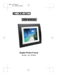
10.Wiring Diagrams
10..1. Indoor unit
Appendix
Wring Diagram
HSM18HEKC/HRAC03/R2(DB) HUM18HC03/R2(DB) -SM
10.2.Outdoor unit
287'225:,5,1*',$*5$0
:$51,1*
02'8/(%2$5'
&$87,21
CN6
CN9 CN8
'21
7728&+&$3$&,725(9(1$)7(5
3/8*2))'$1*(52)(/(&75,&6+2&.
7KHFDSDFLWRUUHWDLQVKLJK
YROWDJHHYHQDIWHUWKHSOXJRII
)RU\RXUVDIHW\EHVXUHWRZDLW
DWOHDVWPLQXWHVDIWHUSOXJ
RIIDQGXVHDWHVWHUWRFRQILUP
WKHYROWDJHEHWZHHQFRQQHFWRU3
DQG1RQPRGXOHERDUGLVOHVV
WKDQ'&9EHIRUHVWDUW
VHUYLFLQJ
AC-N AC-L
CN11 CN10
CN1
CN7
CN4CN3CN2
CN5
%/
WRGRXEOHZD\DLU
H[FKDQJHPRWRU
%
:
:
%
CN1
25
CN26
CN22
CN3
PE
CN2
CN24
TO INDOOR UNIT
CN23
'&)$102725
3)&5($&725
MAIN CONTROL BOARD
AC-N AC-L
CN8 CN9
CN13
(/(&75,&
(;3$16,219$/9(
(OHFWULF
+HDWLQJ&DEOH
:$<9$/9(
<*˖<(//2:*5((1 Remark ˖the dotted parts are
optional for different unit.
25˖25$1*(
7(036(1625
$&)$102725
&2035(6625',6&+$5*(
BL BL
WRVLQJOHZD\
DLUH[FKDQJHPRWRU
SUCTION TEMP.SENSOR
CN16
&1
CN20 CN19 CN18 CN17
7(036(1625
7(50,1$/
%/2&.
&1
CN15 CN14
'()5267
CN10
FUSE2
AMBIENT TEMP.SENSOR
$9$&
&1
CN4
5
'HVFULSWLRQ
/(')ODVK
7LPHV
2XWGRRU((3520HUURU
7KHSURWHFWLRQRI,30
2YHUFXUUHQWSURWHFWLRQ
RI$&HOHFWULFLW\
&RPPXQLFDWLRQIDXOW
EHWZHHQWKH,30DQG&%'
2YHUSUHVVXUHRU2YHUKHDW
SURWHFWLRQIRUWKHFRPSUHVVRU
3RZHUYROWDJHLVWRRKLJKRUORZ
2YHUKHDWSURWHFWLRQIRU
H[KDXVWWHPSHUDWXUH
)URVWUHPRYLQJWHPSHUDWXUH
VHQVRUIDLOXUH
$PELHQWWHPSHUDWXUHVHQVRUIDLOXUH
([KDXVWWHPSHUDWXUHVHQVRUIDLOXUH
'HYLDWHIURPWKHQRUPDO
IRUWKHFRPSUHVVRU
/RRSRIWKHVWDWLRQGHWHFWHUURU
2YHUFXUUHQWRIWKHFRPSUHVVRU
2YHUFXUUHQWSURWHFWLRQIRU
VLQJOHSKDVHRIWKHFRPSUHVVRU
Domestic air conditioner
32:(5
Wring Diagram
HSM18HEKC/HRAC03/R2(DB) HUM18HC03/R2(DB) -SM
11.Circuit Diagrams
11.1.Indoor unit
+5V
R45
10K
R46
1K
C25
R55
R59
R62
R63
1K
100
R65
R66
100
100
REV
SCK
RCK
SER
GND
+5V
COM2
COM3
100
100
0.1UF
+5V
R301
10K
R3
R2
C2
C10
10K
2K
IC1
R40
10K
P1
2SA1037AK
R1
10K
R61
10K
TXD
RXD
ZERO
+5V
C27
0.001uF
C5
2
1
IRQ
E5
+5V
CN5
TJC8-02
0.1UF
100uF-16V
R20
CN7
51K
3
2
1
R58
C16
1K
1
2
3
4
5
6
7
8
9
10
11
12
595 SER
13
595 RCK
14
595 SCK
15
GND
16
+5V
17
PG Feedback 18
PG output 19
20
21
22
0.001UF
+5V
+5V
+12V
N5
10K
25
1
2
R21
27
R23
B2B-XH-A
10K
R9
+5V
B
SW3
R18
XT1
JSS1270
R29 3.3K
A
R11
1M
N4
2SC2412
4.7K
R53
R110
10K
3
10K
FCR8.0MC5
1
TJC8-02
RESET
PTC0
PTC1
PTC2
PTC3
PTC4
PTC5
PTC6
PTE0/TXD
PTE1/RXD
IRQ
PTD0/SS
PTD1/MISO
PTD2/MOSI
PTD3/SPSCK
VSS
VDD
PTD4/T1CH0
PTD5/T1CH1
PTD6/T2CH0
PTD7/T2CH1
PTB0/AD0
44
43
42
41
40
39
38
37
36
35
34
33
32
31
30
29
28
27
26
25
24
23
PTE4/OSC1
PTE3/OSC2
PTE2
VSSA
VDDA
PTA7/KBD7
PTA6/KBD6
PTA5/KBD5
PTA4/KBD4
PTA3/KBD3
PTA2/KBD2
PTA1/KBD1
PTA0/KBD0
VREFL
VREFH
PTB7/AD7
PTB6/AD6
PTB5/AD5
PTB4/AD4
PTB3/AD3
PTB2/AD2
PTB1/AD1
OSC1
OSC2
R30
R25
R26
10K 2
10K 3
1K4
R57
R56
1K6
1K7
IC4
ULN2003
16
15
14
13
12
11
10
9
5
GND
+5V
E2 SCL
E2 SDA
+5V
8
DATA
C20
+5V
R28 1K
GND
+5V
+5V
B3P5-VH
R33
R32
R31
R34
10K
10K
10K
10K
+12v
0.1UF
R67
L0
C19
CBB61-1.2uf-450VAC
R64 120 -1W
C22
3
2
1
TLP3526
10K
R36 1K
C12
0.1UF
IC8
L1
+5V
171uH-800mA-1KHZ -LHB1308-171
CN12
4.7uF-16V E2
E3 4.7uF-16V
1
2
CN8
R35
1K
1K
C13
R37
C14
0.01UF
0.01UF
TJC8-02
0.01uf-50V
680
+12V
MKP61-103-275V
+5V
R47
CN10
TJC8-02
5
4
3
2
1
+12V
N
CN2
CN9-1
S5B-PH
0.001UF
C23
10K
CN13
R22
0.01UF
2SC2412
JSS1270
R43 3.3K
560
2
1
10K
R19
35
SW2
10K
MC908GT16CFBE
C15
B3B-EH-A
R12
10K
E2
CN11
C18
0.1UF
XT1
0.1UF
8
7
6
5
2
2K
R4
A0
VCC
A1
TEST
A2
SCL
VSS
SDA
AT24C02B
B8B-PH
+5V
+5V
1
2
3
4
R68
C9
IC7
R10
8
7
6
5
4
3
2
1
+5V
R302
10K
0.01UF
0.1UF
CN6
SW1-1
JTP1288LA
R16 1K
C7
+5v
2
1
TSVC-1
1
SW1
4
3
2
1
R38
R27
4.7K 1% S4B-XH-A
4.7K 1%
R303
BUZZ1
BEEP-PKM13EPY-4002
N
L0
10K
+12v
CON2
D8
RLS4148
K2
892N-1AC-C
R60 4.7K
FLZ
(L_IN)
1
CON1
1
+12V
R24
R48 220
N7
2K
2SC2412
10K
R71
R108
47K-2W
R104
100K-1/4W
+5V
D101
R106
L
ZD101
1N4746A(18V-1W)
C102
0.047uF-50V
R101
TXD
1K
47K-2W
1N4007
IC101
PC851
+5V
N
E101
100uF-50V
R102
2K
IC102
CON6
C103
2.2nf-250VAC
1K
C101
0.001uF
1
R105
4.7K-1/4w
TLP421
N
CN3
1
2
3
S(N-W)
5289-2A
1
D102
R107
CON7
COM
2K-2W
1N4007
+5V
+5V
R17
R14
10K
4.7K
R39
N2
2SC2412
L
L0
FUSE1
T3.15A-250V AC
N
R201
R13
0.01UF
4.7K
R202
4.7K
4.7K
N3
2SC2412
C17
0.001UF
C3
CN4
N
MKP61-104-275V
3
2
1
B3B-XH-A
+12V
D5
IC3
D3
1N4007
D4
1N4007
+5V
3
1N4007
E4
D2
1N4007
D1
1N4007
MC7805CT
1
2
RV1
S14K350
1K
2K
C8
NERTB-1.5-2P
2
CON3
10K
2
1
1
1
R15
CN1
ZERO
R103
RXD
C1
E1
2200uF-35V
0.1UF
C4
470uF-16V
0.1UF
109
Domestic air conditioner
Wring Diagram
HSM18HEKC/HRAC03/R2(DB) HUM18HC03/R2(DB) -SM
11.2.Outdoor unit
11.2.1 Control Board Circuit Diagrams
J24 J25 J26 J27
R3
1
2K/2W
COM
+5V
CY7
222/250VAC
GND
1
5V
2
RST
3
MODE
4
3
R98
10K
3 IC11
2
4
1
TLP851/PC851
J18
R4
2K
1 IC10
4
2
3
FLASH
TLP421/PS2561
R47
R50
1K
5.1K/1%
P1
2SA1037AK
C20
102/50V
CN33
2
White
1
R46
0
+5V
R97
R51
10K
10K
CN30
GND
1
PCJ35
2
HEAT
3
COOL
4
TEST/SS
5
K4
K6
1
1
5
4
3
2
1
CN13
9
8
7
6
5
4
3
2
1
CN12
1
2
1
1
2
1
3
2
1
1
CN10
K3
K1
K2
R88
+12V
TQ(White)
47K/1%
1K
1K
1K
1K
J17
Com with Module (Black)
CN32
TEST/SS
1
GND
2
J32
K5
C
C
2U/450V
C1
2SC2412K
N4
10K R87
4.7K
J34
D6
12V-5A-892H(N)-1AC-C
12V-5A-892H(N)-1AC-C
12V-5A-892-1CC-C
LL4148 CN17
12V-25A-891P-1A-C
12V-5A-892H(N)-1AC-C
12V-5A-892H(N)-1AC-C
+5V
+5V +5V
3
D11
D5
+12V+12V
J6
J33
2
2SC2412K
P
LL4148
2SC2412K LL4148
N5
J7
J15
1
N3
E11
N
+15V+15V
J23
J16
4.7U/16V
C23
C24
C25
C26
J13
J4
J10
J14
J37
J8
CN18
104/50V
R89
R85
R84 104/50V
J12
J38
J3
104/50V 104/50V
3
R92 0
10K
10K 4.7K
+5V
2
Comment: 2SC2412K
E12
0
+5V
1
R38
R93
4.7U/16V
N1
0
C10
62
51
1K
R83
R94
R91
VCC
TX
0
330
61
52
CN19
1K
R81
R99
VREF
XQ
10K
104/50V 59
53
1K
R79
R39
AVSS
CS
2
R40 5.1K/1%
13
54
J36
1K
R77
DC-FANSPEED
HW
1
10K
E13
36
46
DC FAN PG
Fre Adjust
4.7U/16V
41
31
J9 R41 1K
J5
C14
CN20
Indoor Com OUT Fault Light
38
55
R75
2K
Indoor Com IN
SW-1
102/50V
37
56
J22
3
PC COM
SW-2
4.7K
2
45
60
E14
NC
HEAT-2
R102
28
47
1
R86
4.7U/16V
Terminal Pro
Fan/E-Valve select
27
29
0
MODULE COMOUT SDA
C19
26
30
104/50V
N6
MODULE COM IN
SCL
J2
44
42
J21
+5V Comment: 2SC2412K
NC
H/L FAN SPEED
R100
CN31
24
57
J1
R42
TEST-EN
FAN
4.7K
50
58
VSS
4-WAY
1
330
23
63
R101
COOL-EN
HEAT-1
2
R43
22
64
4.7K
HEAT-EN
PTC
+5V
3
6
1
0
RESET
E-VALVE-D
4
9
2
R104
XIN
E-VALVE-C
7
4
XOUT
E-VALVE-B
0
8
5
R44
J20
VSS
E-VALVE-A
48
3
VSS
MODE
IC7 ULN2003
1K
49
43
C16
R103
VSS
NC
R66
1K 1
10
40
16
Comment: 102/50V
VCC
NC
R67
1K 2
4.7K
15
14
39
CN16
NC
NC
R68
1K 3
14
15
35
NC
NC
D
R69
1K 4
17
34
13
1
C
NC
NC
R70
1K 5
18
33
12
2
NC
NC
J39 R71
B
1K
19
32
6
11
3
NC
NC
J40 R72
A
IC5
1K
7
10
4
20
16
+5V
NC
NC
+5V
GND 12V
5
21
12
R5F212A8SNFA
NC
NC
R61
6
25
11
NC
NC
C13
R95
R96
2K
R59
104/50V
10K
10K
+12V
R62
2K
10K
P2
R63
IC6 AT24C02B
2SA1037AK
560
SW1
5
4
R60
SDA
GND
1
4
6
3
SCL
GND
10K
2
3
7
2
R64
GND
GND
1
R65 8
10K
VCC
GND
10K
C12
+5V
104/50V
1
3
R52
10K
R53
10K
R54
10K
R55
R56
R57
R58
+5V
R48
10K
R49
10K
J19
CN23
5V
3
COM
2
GND
1
H
XQ(Red)
4
2
1N4007
CY10
222/250VAC
CN7
L
HW(Yellow) CS(White)
2
PC817A
1 IC9
PC817A
D1
C COM
SW TEST(BLUE)
1
3
R37 330
CN4
C
20K/1%
4 IC8
R35 1K
H
E-valve(White)
E9
47U/25V
L
20K/1%
R33
2.2K
R36 1K
White BlackCOM
20K/1%
103/50V
C15
( )
B
FUSE2
T1A/250V
R74 10K/1%
C22 102/50V
+15V
R34 1K
ZD2
10V/0.5W
R13 330/1W
ZD3
5.1V/0.5W
CX7
104/275V
W
R80
CN21
310V
1
2
0V
3
15V
4
5
6
ST
R82
N
P
R12
100/1W CX4
103/275V
R78
RA-362M
COM
400N
R76
PE
S14K350
8MH/10A
J28 J29 J30 J31
PTC1
ERROR
LED1
RV3
S14K350
CX3
225/275V
Two-speed AC Fan CN14 CN15
R73 10K/1%
C21 102/50V
RV2
SA1
CX2
225/275V
Three-speed AC Fan
XT1
4M
CN3
Yellow/Green 1
8MH/10A
CY1
472/250V/275V
AC-N
CY2
472/250V/275V
White 1
L2
R2
1M
CY5
472/250V/275V
CX1
225/275V
COM heater
Four -Way Comment:
CN25 CN11 CN27 CN36
FUCTION TEST(White)
104/50V
C11
R1
1M
CY3
103/250V/275V
RV1
S14K350
CY6
472/250V/275V
L1
T25A 250VAC
AC-L OUT
CN9
1
1
FUSE1
Black 1
AC-L
CN1
AC-N OUT
CN8
CY4
103/250V/275V
CN2
AC-L
AC-N
CN6
1
CN5
ZD1
IN5948B
R25
D7
6 MBR1100\SB1100
1
10K
FB
3
R29
E6
47 100U/16V
GND
8
7
NC
R18 47
6
NCP1200P100
R15
15
M1
C2
102/100V
222/250VAC
220 220
CN22
+15V
1
2
3
E4
470U/25V
5
R17
330/1W
C6
104/50V
E3
22U/25V
4
IC2
( )
R32
5.1K/1%
IRFUC20
2/1W
CY9
D9
4 MUR115\MUR130\ER106
5
GNDDRV
10K
L3
20UH/1A
E5
470U/25V
7
CS VCC
J11 4
R26
1K
R27
IC1
ADJ HV
2
R90 0
C4
103/50V
R16
+5VD
R24
5.1K/1%
E8
C9
Comment: 100U/16V
104/50V
R21
CX5
104/275V
Vout
R20
3
D10
ER106
+5V
3
R28 5.1K/1%
CY8
472/1KV
L7805CV
2
R14
100K/2W
1
47
C3
IC4
+12V
Comment: E22034
102/100V
1
T1
Vin
D8
10 MBR3100\ER302
E7
C8
R22
470U/25V
104/50V 1K/0.5W
9
C7
104/50V
P
N
R19
PC817A
3
1
2
R30
1K
R31
1K
C5
104/50V
IC3
TL431C
110
Domestic air conditioner
Wring Diagram
HSM18HEKC/HRAC03/R2(DB) HUM18HC03/R2(DB) -SM
CN26
P
1
250 Connector
P
R23
220K/2W
E1
E2
CX6
105/275VAC
680U/400V/450V 680U/400V/450V
LED2
POWER
N
1
250 Connector
CN24
N
11.2.2 Module Board Circuit Diagram
L
5. 2MH/15A
CN7
2
LO
CN1
P
D207
FFA30U60DN
24
P
1
3
IC8
C404
SGH40N60UF
474/275V
C405
104/275V
CN2
U
680U/400V*2
V 22
CN3
V
W 21
CN4
W
6
R220 82
5
IC5
7
C208
104
HA17393AF
15V
R230
D203
US1M
C032
104
D202
US1M
C034
104
D201
US1M
C036
104
10
8
IC6
R207
1
R209
3
C201
104
4 HA1630D06
R211
1K
1K
1K
6
IC6
7
5
HA1630D06
R210 6. 8K
5V
1
2
3
4
5V
5V
R202
6. 2K
R205
1K
2
IC4
1
4 HA1630D06
R206
1K
R201
1K
6
R203
1K
5
R204 6. 2K
IC4
7
15V
CN10
HA1630D06
C504
100U/25V
3
2
1
C501
100U/16V
POWER(BLUE)
5V
PC2
330
PC817A
MMBT9013
TR3
3
2
1
C018
103
R016
1K
R012
4. 7K
R015
CN11
PC1
R014
C017
223
330
R013
C016
472
PC817A
8
7
6
5
R010
4. 7K
8
3
C202
104
IC3
24C04
C011
104
5V
R019
4. 7K
R018 4. 7K
TR2
C014
MMBT9012
102
R229 4.22K R228130K R227130K R226130K
2
VNO
VNC
VN1
CIN
FO
UN
WN
VN
WP
VNC
VP
UP
VWFB
VVFB
VP1
8
15V
9 10 11 12 13 14 15 16 17
R213 100
1
C203
104
R208
6. 8K
R212
9. 1K
7
IC5
C204104
8
4 HA17393AF
R011
4. 7K
6
D206
24V/1W
C023
C413
100U/25V
5V
R224
4. 7K
5
224
C205
223
R218 82
C207
104
4
2
5V
C412
47U/25V
C411
47U/25V
C022
103
40
39
38
37
36
35
34
33
32
31
30
29 R231 4.7K
28
27
26
25
24
23
22
21
R221 140
3
R008
4. 7K
5V
5V
C003
104
C002
104
C006
474
C004
104
41
R009 4. 7K 42
43
44
45
46
47
R006 100
R005 4. 7K
48
C020
49
102
50
C019
R017 4. 7K
51
103
52
53
54
C028
55
R007 4. 7K
103
56
57
58
CN12
59
RES
7
60
FWP
6
TXD
5
RXD
4
MD1
3
5V
2
GND
1
20
19
18
17
16
15
14
13
12
11C001
10 104
9
8
7 C015
6 102
5
4
3
2
1
C410
47U/25V
D204
LL4148
IC1
SH7046
61
62
63
64
R001 4.7K
65
66
R002 4.7K
67
68
R004 4.7K
69
70
71
72
73
74
C008 75
76
474
77
C009
78
471
79
80
C502
100U/25V
TR1
MMBT9013
3
R222
C005
104
5V
C007
474
R216
10
2
R225
5V
C029
471
330
C012
104
5V
R003 4.7K
15V
8
IC7
6
TLP251
5
N
C030
471
3
R217 1K
5V
2
20
0. 015/5W
LL4148
4
RS2
N
CN5
R214
100
VUFB
10K
RS1
0. 015/5W
D205
BG1
D25B X60B
R223
C406
104/275V
R215
CN9
AC -N
communicate
U 23
PM1
PS21965-AT
R219 1K
CN8
AC -L
CN6
LI
X1 10M
IC2
T600D
C013
104
4. 7U/16V
C503
D208
LL4148
5V
330
111
Domestic air conditioner
Appendix
HSM18HEKC/HRAC03/R2(DB) HUM18HC03/R2(DB) -SM
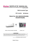
12 Description of coding rules of unit model
H
1
M
S
H
8
EKC
0
R
3
(D
2
B)
DC Inverter
Refrigerant type:R2(R410A)
Applicable voltage:3(220~230V)
Applicable frequency:0(50HZ)
apparance of indoor unit is EKC series
H-heat pump
Nominal cooling capacity (18000 BTU/h)
M-Multi match:one outdoor unit can match different indoor unit
The structure code of indoor unit: S(wall-mounted)
H-Abbreviation of Haier
HSM18HRAC03/R2(DB) means 18000BTU.
H
U
1
M
8
H
0
C
R
3
2
(D
B)
DC Inverter
Refrigerant type:R2(R410A)
Applicable voltage:3(220~230V)
Applicable frequency:0(50HZ)
C is serial number
H-heat pump
Nominal cooling capacity (18000BTU/h)
M-Multi match:one outdoor unit can match different indoor unit
The structure code of outdoor unit:
H-Abbreviation of Haier
HUM18HC03/R2(DB) means18000BTU.
Examples:
HSU-07RD03/R1,It represents wall-mounted split type heat pump a
capacity is 7000BTU/h,and the power supply is 220-230V/50Hz,”D”
ir condition
er .The cooling
means the developing
sequence,and"R1" means the refrigerant is R407C.
112
Domestic Air Conditioner
HSM18HEKC/HRAC03/R2(DB) HUM18HC03/R2(DB) -SM
The end
Sincere Forever
Haier Group
Zhao Ni
Zhang Fei
Yang Bifei
86 532 88936935
Wu Hongjin