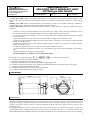
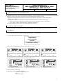
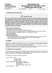
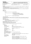
1
USER MANUAL FOR
EXPLOSION PROOF EMERGENCY LIGHT
FITTING type FLXE 118 LED
d.o.o.
10090 Zagreb, Medarska 69
tel. 049 222900, fax 049 426450
e-mail: [email protected]
www.tepex.hr
No: TEPEx.RS.053
Rev : 0
Date: 02.2015.
1. GENERAL SAFETY INSTRUCTIONS
WARNING
The user manual contains basic information about the product. Mounting, installation, usage and maintenance
should be carried out under this user manual to provide and ensure safe operation within the nominal
characteristics. This user manual complement national Regulation and Standards. The responsible person shall
ensure their implementation. Failure off implement this user manual can reduce explosion protection and
endanger people, property and the environment. Any improper and illegal actions as well as non-compliance
with the provisions of this user manual excludes all responsibility by manufacturer side.
Before installation/commissioning:
- Carefully read all instructions,
- Execute proper training of responsible personnel,
- Check that the contents of these instructions is fully understandable by the responsible personnel,
- Make sure that all the requirements and national Regulations as well as all special security measures are applied.
In lack of understanding:
- Contact the manufacturer.
During operation:
- Ensure that this user manual and other work instructions are available to the responsible staff at all times,
- Check the implementation of these instructions and all other safety user’s instructions.
2. PURPOSE
Explosion protected emergency luminaire type FLXE 118 LED ../. with autonomous power supply is intended for
emergency and general lighting in areas with a potentially explosive atmosphere of gases, vapors and dust as well as
their combinations in hazardous areas 1, 2, 21, 22, according to EN 60079-10- 1 / -2:2009.
Explosion protected emergency luminaire allows planning and execution of emergency lighting and electrical
requirements in accordance with EN 1838: 2008 and EN 50172: 2008 standard.
3. CONFORMITY WITH STANDARDS
The product complies with the EN 60598-1: 2008 / A11: 2009, EN 60598-2-22: 1998, EN 62034: 2012, EN 62031:
2008 and EN 62471: 2008 and all related regulations.
The product complies with the ATEX Directive 94/9 EC and standards:
- EN 60079-0: 2012,
- EN 60079-1: 2007,
- EN 60079-7: 2007,
- EN 60079-31: 2009.
The product is developed, manufactured and tested according to the prior art in accordance with EN 9001: 2008 and EN
ISO / IEC 80079-34: 2011.
- The product is in compliance with the LV Directive 2006/95 EC.
- The product is in compliance with the RoHS Directive 2011/65 EU.
- The product is in compliance with the EMC Directive 2004/108 EC.
4. DEGREE OF PROTECTION AND TECHNICAL DATA
Certificate:
Category and
explosion protection:
EXA 13 ATEX . . . .
2G Ex d IIC T6 Gb or II 2G Ex d e IIC T6 Gb
2D Ex tb IIIC T80°C Db
Operating temperature range:
Degree of protection:
Impact resistance:
-20 oC : +50 oC
IP66 / IP67
IK 08
1
USER MANUAL FOR
EXPLOSION PROOF EMERGENCY LIGHT
FITTING type FLXE 118 LED
d.o.o.
10090 Zagreb, Medarska 69
tel. 049 222900, fax 049 426450
e-mail: [email protected]
www.tepex.hr
No: TEPEx.RS.053
Class of protection:
Rated operational voltage:
Rated current:
Power factor:
Rated autonomy:
Rated power and type of luminaire:
Measuring luminous flux(power and
battery operation):
Correlated colour temperature:
Color rendering index (CRI):
Average rated life of LED:
Visibility (EN 1838)
Operation efficiency:
Change-over
Battery operation:
Mains supply operation:
Battery:
Battery life:
Charging time:
Connection terminals:
Storage:
Rev : 0
Date: 02.2015.
I (protective earthing)
24 - 240 V AC/DC ± 10 % (see table of version)
10 VA
cos φ > 0,95
3 hours
LED 2 x 1,2 W
chip-on-board technology
200 lm
6500 K
>70
≥50 000 hours
22 m
~ 80 %
U < 0,8 Un for more than 0,5 seconds
U > 0,9 Un for more than 1 second
Ni-Mh Saft VHT 3,6 V/2 Ah, IEC 61951-2:2011, built-in
lighting, microprocessor controlled charging, discharging
and battery monitoring
min. 2000 charging cycles or min. 4 years in nominal
operating conditions
15 hours (12 hours > 90% nominal autonomy),
continuous battery recharge
FLXE 118 LED .0/., FLXE 118 LED .1/.
- snap-in terminals for mains supply L, L´, N, PE, TEST,
RESET, 2,5 mm2 max. per terminal, solid, stranded,
flexible - sol(r), s(r), f
FLXE 118 LED .2/.
- screw terminals, of Ex de Adapter ADP, for mains supply
L, L´, N, PE as well as TEST and RESET connectors; 2,5mm2 max. per terminal, solid, stranded, flexible sol(r), s(r), f; nominal fastening torque 1,2Nm;
- Ex e cable gland ISO 25 on Adapter ADP for cable ø615mm; nominal fastening torque 2,5 Nm
- earthing terminal (external) (equipotential), 2 x 6mm2
max. per terminal, solid, stranded, flexible - sol(r), s(r), f;
nominal fastening torque 2,2 Nm
- max. 4 months on temperature +5 oC : +25 oC and
humidity 65 ± 5%,
- max. 1 month on temperature -20 oC : +5 oC or +25 oC :
+70 oC and humidity 65 ± 5 %
5. ISOCANDELA DIAGRAM [l/cd]
2
d.o.o.
10090 Zagreb, Medarska 69
tel. 049 222900, fax 049 426450
e-mail: [email protected]
www.tepex.hr
USER MANUAL FOR
EXPLOSION PROOF EMERGENCY LIGHT
FITTING type FLXE 118 LED
No: TEPEx.RS.053
Rev : 0
Date: 02.2015.
6. MODEL CODE:
FLXE 118 LED . . / .
Basic model type
Rated voltage:
- 0 - 24 V AC
- 1 - 24 V DC
- 2 - 110 - 127 V AC
- 3 - 220 - 240 V AC
Cable entry:
- 0 - Ex d cable entry 2 x M20, ISO 965-1, ISO 965-3
- 1 - Ex d cable entry 2 x 3/4"NPT, ANSI/ASME B1.20.1
- 2 - Ex d cable entry 2 x M20, ISO 965-1, ISO 965-3 with one mounted
Ex d e adapter type ADP 24/1 and one Ex d plug
Emergency description (pictogram):
In accordance with DIN 4844-2
0
Without markings
5
1
6
2
7
3
8
4
7. OPERATING MODES
The lamp can operate with two types of connection:
a) Maintained (Dauerschaltung)
The light fitting can be used for general and orientation lighting with mains power supply via L' (installation
switch). In case of voltage drop or an interruption in the mains power supply L, the light fitting will continue to
operate in battery-powered mode, regardless of the status of installation switch L' (ON/OFF)..
b) Non maintained (Bereitschaftschaltung)
In case of voltage drop or an interruption in the mains power supply L, the light fitting will operate only in batterypowered mode.
In both types of the connection in the presence of continuous phase L, it is possible to verify the correctness of the
emergency system by turning on the switch in the TEST circuit.
In both types of the connection in the presence or interruption of continuous phase L, regardless of the status of the
power supply L', it is possible to turn OFF the emergency lighting, by turning ON the switch in the RESET circuit.
In case of an interruption in the mains power supply and then recovery of continuous phase L (L'), if the installation
switch is turned ON, the light fitting will work in operating mode powered by the main power supply.
Max. 20 light fitting in line wiring can be connected per external switch. For larger numbers of line wiring of
TEST/RESET circuits and longer cable lengths, please consult the manufacturer.
The light fitting is equipped with an electronic set for emergency lighting self-monitoring function and status signaling
function. Self-monitoring is permanent. Status signalization is indicated with red and green indicator LED when the
light fitting does not work.
3
USER MANUAL FOR
EXPLOSION PROOF EMERGENCY LIGHT
FITTING type FLXE 118 LED
d.o.o.
10090 Zagreb, Medarska 69
tel. 049 222900, fax 049 426450
e-mail: [email protected]
www.tepex.hr
No: TEPEx.RS.053
Rev : 0
Date: 02.2015.
Constant green LED, indicates the optimal functionality of the emergency system and the nominal autonomy, with
batteries rated capacity within the rated ambient temperature. Batteries are permanently charged in "trickle charge"
mode.
Blinking green LED, indicates the functionality of the emergency system in non-nominal autonomy. Autonomy is
between 1 and 3 hours. Batteries are under charging phase with rated current.
Constant Red LED, indicates the dysfunction of the emergency system. Reasons for this may include some of the
following:
- batteries are empty. The lamp should be left on the main power supply. After a while the signalization will by
itself transfer into green LED, blinking lights and emergency lighting will become functional
- Ex d cover isn't screwed completely. Screw until green LED appears, blinking lights and emergency lighting
becomes functional,
- connection is made incorrectly. Connection should be made according to the connection scheme
- batteries are old, permanently charged with rated current and are overheating. It is necessary to replace the LED
module, type FLXE 10-130,
- batteries are old and can't reach the required charging voltage and capacity. It is necessary to replace the LED
module, type FLXE 10-130,
- the fuse in the battery circuit Ø 5 x 20 mm 1.25 AT is faulty. Should be replaced.
Faulty fuse indicates the defective batteries. You will probably need to replace the LED module, type FLXE 10130,
- ambient temperature is outside specification limits.
Self-monitoring does not include a control of the LEDs validity.
Description of tag on the light fitting
, according to EN 60598-2-22:
X - emergency light fitting with built-in batteries
1 - emergency light fitting in a permanent connection
A - emergency light fitting with self-monitoring and status signaling function
B - emergency light fitting with main power supply option and automatically turn ON after power return option
C - emergency light fitting with RESET function
D - emergency light fitting for use in areas with special hazards
180 - emergency light fitting with autonomy of 3 hours
8. DIMENSION
330
240±1
12
220±1
160±0,5
180±0,5
O13
9. MOUNTING
Standard mounting is performed with suspension or fixing with a screws through an Ø13 mm hole in the housing. Using
accessories for quick installation FLXE 20-170 can be directly fixed on the wall or ceiling - screw accessories Ø8 at a
distance of 230 mm. Using accessories for quick installation FLXE 20-180 can be directly fixed on the pole with
diameter up to 2".
Ex d glands and plugs are not part of the delivery for the types FLXE 118 LED .0 /. and FLXE 118 LED .1 /. but it must
be provided by users. Standard design lamps assumes enclosure with blind cable entry’s for volume protection. For
lamp model with TEST and RESET function lamp shall be equipped with two glands Ex d or Ex de with two adapters.
4
USER MANUAL FOR
EXPLOSION PROOF EMERGENCY LIGHT
FITTING type FLXE 118 LED
d.o.o.
10090 Zagreb, Medarska 69
tel. 049 222900, fax 049 426450
e-mail: [email protected]
www.tepex.hr
No: TEPEx.RS.053
Rev : 0
Date: 02.2015.
When installing the user should comply with the instructions of the manufacturer. Performance FLXE 118 LED .2 /. the
factory is equipped with an Ex de adapter and one blind plug. If the user requests through-wiring, it is necessary to use
two Ex de adapter or two Ex d glands, but in this case TEST and RESET function can not be used.
The lamp comes with a lid twisted entirely in the housing and mechanically locked screw M5x10 ISO 4027wich does
not allowed self-loosening.
After each opening, lamp threat should be protected by protective agent threads.
10. INSTALLING AND PUTTING INTO OPERATION
Network connection is performed through screwless terminals located on the LED module FLXE 10-130 according to
wiring diagram and technical data:
Maintained:
Permanent main line has to be connected to the L(1) terminal. Phase conductor for power supply has to be connected
through installation switch to the L'(4) terminal. User should be careful that phase L and L' are the same phase. Neutral
conductor has to be connected to the N(3) terminal and protective earth conductor to the PE(2) terminal.
Non maintained:
Permanent main line has to be connected to the L(1) terminal. Neutral conductor has to be connected to the N(3)
terminal and protective earth conductor to the PE(2) terminal. L'(4) terminal is not connected.
External grounding, equipotential - IP is connected to an external terminal provided with a grounding conductor 6 mm2
solid (r), s (r), f.
Label with a wiring diagram is on the LED module FLXE 10-130.
If the electrical connection is performed through Ex de adapter, internal wiring is done by the manufacturer.
The electrical connection to the terminals of adapter have to be performed according to wiring diagram below.
“RESET” circuit is connected to the (5) and (6) terminals and “TEST” circuit to the (7) and (8) terminals.
In the case of parallel connection more than one RESET or TEST circuit one should be careful that the
terminals of the same polarity are always short-circuited.
INDIREKTAN UVOD - Ex d e adapter
DIREKTAN UVOD - Ex d uvodnica
L1
L1
L2
L2
N
N
PE
PE
BROWN
PERMANENT LINE - BLACK
L2
PROTECTIVE EARTH
GREEN-YELLOW
NEUTRAL - BLUE
LINE IN FROM SWITCH - BROWN
PE
1
2
2
3
4
GREEN-YELLOW
BLACK
N
L´
1
2
2
3
4
L
N
L´
LED modul
FLXE 10-130
L1
N
RED
BLACK
BLUE
L
5
6
7
8
RESET
TEST
PE
R
O
PR EU O
N FR
N
LINE I
MA
M
TE
NE
NT
C
LIN
TR TIVE
E AL
EA
BL
RT
-B
AC
L
-G
K
SW UE
RE
I TC
H
WIRING
-
- YELLOW
N
OW
BR
RED
BLACK
8 7 6 5
EN
FACTORY
4 3 2 2 1
TEST
RESET
L´ N
L
4 3 2 2 1
LED modul
FLXE 10-130
L´ N
L
5
USER MANUAL FOR
EXPLOSION PROOF EMERGENCY LIGHT
FITTING type FLXE 118 LED
d.o.o.
10090 Zagreb, Medarska 69
tel. 049 222900, fax 049 426450
e-mail: [email protected]
www.tepex.hr
No: TEPEx.RS.053
Rev : 0
Date: 02.2015.
When commissioning the control insulation measurements should be performed with the test voltage max. 1000 V DC
and the test current 1 mA and between:
- Neutral and earth conductor
- Phase conductor L and earth conductor
- Phase conductor L 'and earth conductor
Testing between phase and neutral conductor is not allowed and will be provided with the wrong values because the
electrical control gear is connected to the input circuit. For successfully testing it is necessary to disconnect the
electrical control gear. This can be achieved by switching off the insulating coupling which is achieved by raising the
assembly of the window frame.
U
N
L
L'
PE
U
N
L
L'
PE
U
N
L
L'
PE
N
L
L'
PE
11. SPARE PARTS AND ACCESSORIES
SKICA
DESCRIPTION
CODE
Housing cover
set
SKETCH
DESCRIPTION
CODE
FLXE
10-110
Ex d cable gland
ISO 20
SPUD 20
Cover gasket
FLXE
FLXE
10-120
Ex d cable gland
3/4"NPT
SPUD
3/4"NPT
Base plate FLXE
FLXE
10-130
Ex d plug
ISO 20
SPCD 20
Protective grid
FLXE set
FLXE
20-140
Ex d plug 3/4"NPT
SPCD
3/4"NPT
External
reflector FLXE
FLXE
20-150
FLXE wall/ceiling
mounting set
FLXE
20-170
Junction box
ADP 23
ADP
10-160
FLXE pipe mounting set
FLXE
20-180
6
USER MANUAL FOR
EXPLOSION PROOF EMERGENCY LIGHT
FITTING type FLXE 118 LED
d.o.o.
10090 Zagreb, Medarska 69
tel. 049 222900, fax 049 426450
e-mail: [email protected]
www.tepex.hr
No: TEPEx.RS.053
Rev : 0
Date: 02.2015.
12. RESPONSIBILITY AND AUTHORIZATION
This Manual represents the most relevant information about the product. Adequate national laws and regulations supplement
it. Production, usage, certification and supervision are determined at the national level with:
a) Regulations of Equipment and protective systems intended for use in potentially explosive atmospheres
(NN br. 34/10.) and
b) Regulations of minimum requirements for safety and health protection of workers and technical
Inspection of facilities, equipment, installations and devices in potentially explosive atmospheres
(NN br. 39/06, 106/07.), and EU Directive 1999/92/EC (ATEX 137).
The responsible person shall ensure their implementation at the facility.
13. STORAGE AND TRANSPORT
Transport and storage is only allowed in the original packaging, on the way pointed out on the carton box.
14. MARKING
Explosion protected fluorescent lighting fitting, type FLXE 118/. . is labeled with:
- a warning labels with technical data on the housing:
WARNING
DO NOT OPEN WHEN
ENERGIZED
DO NOT OPEN WHEN AN EXPLOSIVE
ATMOSPHERE IS PRESENT
- a label with a wiring diagram on the LED module FLXE 10-130:
x
FLXE 118 LED .0 /.
... V
10 VA 200 lm IP 66 / IP 67
50Hz
2x1,2W
-20°C<Ta<+50°C
II 2G Ex d IIC T6 Gb II 2D Ex tb IIIC T80° Db
EXA 14 ATEX . . . .
x
0722
Medarska 69, Zagreb, Croatia
Made in Croatia
P-
DAT-
FLXE 118 LED .1 /.
... V
x
0722
Medarska 69, Zagreb, Croatia
Made in Croatia
50Hz
2x1,2W
0722
Medarska 69, Zagreb, Croatia
Made in Croatia
FLXE 118 LED .2 /.
... V
50Hz
2x1,2W
10 VA 200 lm IP 66 / IP 67 -20°C<Ta<+50°C
II 2G Ex d IIC T6 Gb II 2D Ex tb IIIC T80° Db
10 VA 200 lm IP 66 / IP 67 -20°C<Ta<+50°C
II 2G Ex d e IIC T6 Gb II 2D Ex tb IIIC T80° Db
EXA 14 ATEX . . . .
EXA 14 ATEX . . . .
P-
DAT-
P-
DAT-
- a label with the wiring diagram in the LED module FLXE 10-130:
EMERGENCY LIGHTING MODULE
L
2
2
N
3
L´
4
RESET
TEST
EMERGENCY LIGHTING MODULE
Medarska 69, Zagreb, Croatia
Made in Croatia
1
0722
EXA 14 ATEX . . . .
FLXE 118 LED . 0 / .
...V
10VA
200lm
II 2G Ex d IIC T6 Gb
II 2D Ex tb IIIC T80°C Db
IP66/IP67
PKK-
5
L
L´
4
RESET
6
7
EN 60598-2-22
8
X 1 ABCD 180
FAULT (RED)
CHARGE (GREEN)
...V
2
3
TEST
0722
EXA 14 ATEX . . . .
FLXE 118 LED . 1 / .
2
N
EMERGENCY LIGHTING MODULE
Medarska 69, Zagreb, Croatia
Made in Croatia
1
10VA
200lm
II 2G Ex d IIC T6 Gb
II 2D Ex tb IIIC T80°C Db
IP66/IP67
PKK-
5
L
2
2
N
3
L´
4
RESET
6
7
EN 60598-2-22
8
X 1 ABCD 180
FAULT (RED)
CHARGE (GREEN)
TEST
Medarska 69, Zagreb, Croatia
Made in Croatia
1
0722
EXA 14 ATEX . . . .
FLXE 118 LED . 2 / .
...V
10VA
200lm
II 2G Ex d e IIC T6 Gb
II 2D Ex tb IIIC T80°C Db
IP66/IP67
PKK-
5
6
7
EN 60598-2-22
8
X 1 ABCD 180
FAULT (RED)
CHARGE (GREEN)
1) data according to model code
2) manufacturer data : - production number,
- number of a single examination,
- date,
- responsible person
7