1
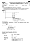
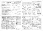
d.o.o. 10090 Zagreb, Medarska 69 tel. +38549222900 fax +38549426450 e-mail: [email protected] USER MANUAL FOR EXPLOSION PROTECTED GROUNDING AND GROUNDING CONTROL DEVICE type GGCD-01/.. No: TEPEx.RS.040 Rev : 2 Date: 25.01.2011. 1. MANUFACTURER TEP Ex d.o.o. , Medarska 69, HR-10090 Zagreb tel. +38549/222-900, fax +38549/426-450, e-mail: tepextepex.hr, www.tepex.hr 2. PURPOSE GGCD 01 device (Grounding and grounding control device) along with the grounding clamps makes the active system for static grounding and grounding control and it is used in areas that may be endangered by explosive mixtures of gas and vapoures of flammable liquid with air, in danger zones 1 i 2 according to the HRN EN 60079-10-1:2009 (EN 60079-10-1:2009). Device ensures that objects like tanks are electrostatic grounded correctly during the loading and unloading of flammable liquids. The device provides a conductive connection to the ground and monitors in parallel the quality of the connection. The electrostatic level of the tank is kept ona a safe level. An occasional discharge in conjunction with sparks is prevented and therefore the explosion protection ensured. 3. DEGREE OF PROTECTION Explosion protection is in accordance with the "general requirements" in the types of protection "flameproof enclosure", “ increased safety”, "intrinsic safety" and "encapsulation" in accordance with standards: HRN EN 60079-0:2009, HRN EN 60079-1:2008, HRN EN 60079-7:2007, HRN EN 60079-11:2007 HRN EN 6007918:2010 (EN 60079-0:2009, EN 60079-1:2007, EN 60079-7:2007, EN 60079-11:2007, EN 60079-18:2009). Apparatus category: II 2G Explosion protection marking: Ex d e [ib] mb IIC T5 Gb Ambient temperature: -20°C > Tamb > +50°C Mechanical protection: IP 66 category 1, according to the EN 60529:1991/A1:2000 Degree of protection: I (protective grounding), according to the EN 61140:2002/A1:2006 Certificate: Ex-Agency [E-1/08] - HREx T 10.024 The device complies with standards: - CENELEC CLC/TR 50404 (Electrostatics-Code of practice for the avoidance of hazards due to static electricity), CEN 1755 +A1 (Safety of industrial trucks-Operation in potentially explosive atmospheres-Use in flammable gas, vapour, mist and dust), BGR 132 – BG Rules for avoiding ignition hazards as a result of electromagnetic charges The product complies with the LV Directive 2006/95/EC, EMC Directive 2004/108/EC and RoHS Directive 2002/95/EC. 1/7 4. MODEL CODE GGCD 01 / . . basic device marking - K1 - type with one clamp K1, with 10m cable, - K2 - type with two clamps K1, with 2 x 10m cable. Each version of GGCD device has two operating modes (which can be selected with control switch): MODE 1 – Device doesn't recognize if object is grounded in any other way in the moment of connecting grounding clamps. It is used when the object because of itself construction can't be isolated from ground (rail cars, tank containers). Pushbutton START has no function in this mode. MODE 2 – Device inside control time (cca 10s) recognize if object is already grounded in some other way with RZ UK < 7 kΩ, and if clamps are connected correctly to grounded object. Mode is started pushing to START pushbutton. It can be used when grounded object is isolated from ground (tank trucks, etc...). Control switch can be locked with padlock in any of operating modes. 5. OPERATING PRINCIPLE Reaction of the ground monitoring device State of grounding process Clamp is not connected, grounding equipment not in use Clamp is directly grounded, e.g. via the loading platform Grounding incorrect • Red indicating lamp ON • Green indicating lamp OFF • Contact OPEN Grounding incorrect (only MOD 2) • Red indicating lamp ON • Green indicating lamp OFF • Contacts OPEN Clamp connected to tank vehicle. Grounding OK • Red indicating lamp OFF • Green indicating lamp ON • Contacts CLOSED Clamp connected to tank vehicle, but cable to the grounding is disconnected. Grounding incorrect • Red indicating lamp ON • Green indicating lamp OFF • Contacts OPEN Clamp connected to tank vehicle. Tank vehicle is grounded subsequently (e.g. via the loading arm). Grounding OK • Red indicating lamp OFF • Green indicating lamp ON • Contacts CLOSED 2/7 6. BLOCK DIAGRAM START CONECTION TO NETWORK SUPLAY CONTACTS CONNECTED PAL1, PAL2 CONNECTED CLAMPS CONNECTED TURN ON MOD2 RED INDICATING LAMP ON CONTACTS NO - CLOSED, NC - OPEN MOD1 RED INDICATING LAMP ON CONTACTS NO - CLOSED, NC - OPEN START RED INDICATING BLINKING t = 10s NO YES RZ> ... RČ1<... RČ2<... CONTINUING LOOP CONTROL NO YES NO RPAL1<... RPAL2<... YES GREEN INDICATING LAMP ON CONTACTS NO - CLOSED,NC - OPEN NO POWER SUPLAY YES END 7. TECHNICAL DATA Nominal voltage Un: Nominal current In: Nominal power P0 : Output circuit: Indicating lamps: Max. r.m.s. voltage Um: Max. open circuit voltage U0: Max. current I0: Max. power P0: Max. external inductance L0: Max. external capacity C0: 230 V ± 10 10%, 50 Hz 50 mA 10 W 2 switch over contacts Un=250 V AC, In=8 A / 230 V, 4 A at cos φ = 0,4 Red: - blinking inside control time (10 sec - MOD2), contacts NO are open, contacts NC are closed, - continuous operation (MOD1 and MOD 2), contacts NO are open, contacts NC are closed Green: - continuous operation (MOD1 and MOD 2), contacts NO are closed, contacts NC are open 253 V 15 V 1,60 mA 6,0 mW - linear characteristics 50 mH 45 nF 3/7 Maximum length of the clamp cable: Connecting terminals: Stripping length: Tightening torque of terminal screws: Cable ferrules: Cover screws: Tightening torque for cover screw: Cable glands and plugs: Tightening torque for cable glands: Tightening torque for plugs: Clamp cable: Dimension (LxWxH): Dimension of clamps holder(L x W x H): Mounting enclosure onto surface: Mounting clamps holder onto surface: Weight (without clamps): Weight of clamps with 10 m cable: 100 m - network suplay terminal, output contacts: 1,5-4 mm2 stranded, flexible - Cable to the grounding point or busbar for equipotential bonding: 25 mm2 max. stranded, flexible 4 mm2 - 10 mm, 25 mm2 - 14 mm terminal 4 mm2 - 0,6 Nm, terminal 25 mm2 - 3,0 Nm Stranded and flexible cables are installed with cable ferrules according to DIN 46228 T1 M6x30 (Z4) - 4,8 A2 1,5 Nm - GGCD 01/K1: 3xM25 Exi cable glands and 2xM25 Exe cable glands for cable Øv= 9-15 mm, 1 x M25 Exi plug, 1 x M25 Exe plug - GGCD 01/K2 - 4xM25 Exi cable glands, 2xM25 Exe cable glands for cable 15 > Øv > 9 mm, 1 x M25 Exe plug - cable gland body 3,5 Nm, - cable gland nut 2,5 Nm 3,5 Nm 3 or 2x1,5 mm2 - cable capacity (wire-wire) 135 nF/km - wire inductance 0,65 mH/km - wire resistance 12,0 Ω/km 255 x 250 x 160 mm without clamps 300 x 300 x 195 mm without clamps With screw kit M6 through the holes in the enclosure Ø7/Ø12 mm at the top of the rectangle 235 x 200 mm With screw kit M8 at the top of the rectangle 225 x 260 mm ca. 6,0 kg ca. 2,5 kg 8. BLOCK DIAGRAM OF DEVICE AND OPERATING INSTRUCTIONS It is generally considered that object is satisfactorily electrostatic grounded if resistance to earth is not higher than 106 Ω. 4/7 Open – closed threshold of output relay depends of clamps resistance RČ=RČ1+RČ2, loop resistance PAL of conduit RPAL and possible resistance object of grounding of outside grounding RZ (just in MOD 2 operation inside control time). That given substitute resistance from Z1 to equipotential bonding determines open – closed threshold RUK ON. In ideal case when RZ=∞ and RPAL=0 in MOD 2 outside control time and in MOD 1 operation: - RČ1 + RČ2 < 1,7 kΩ object is electrostatic grounded, green signal light is on, output NO contact is closed, and NC is open, - increasing RČ1 + RČ2 > 2,3 kΩ is considering that object is not satisfactorily electrostatic grounded, red signal light is turning on, output NO contact is opening and NC is closing. In second case when RZ=0 and RPAL=0 in MOD 2 outside control time and in MOD 1 operation: - RČ1 < 5,0 kΩ object is electrostatic grounded, green signal light is on, output NO contact is closed and NC is open, - increasing RČ1 > 5,6 kΩ s considering that object is not satisfactorily electrostatic grounded, red signal light is turning on, output NO contact is opening and NC is closing. Inside control time in MOD 2 operation in boundary case when are RČ1=0 and RČ2=0 in order to electrostatic grounding is satisfactorily, i.e. that output NO contact is closed, it must be RZ > 7,0 kΩ. 9. INSTALLING, CONTROL, MAINTENANCE AND REPAIR It is necessary to read this manual before installing and usage and if it is needed to request extra informations from manufacturer. Installing and usage of device is allowed only to qualified and authorized persons. Installing of device have to be done in non-voltage state. PAL (equipotential bonding connection) terminals inside device are connected to PA (equipotential bonding connection) busbar or grounding point with two single wire cables. It that case control loop is achieved and permanent monitoring of galvanic continuity connection PAL (equipotential bonding connection) terminal with PA (equipotential bonding connection) busbar or grounding point. Connection is made with conductor with cross-section 6-25 mm2. Electric connection, and cables for output connections inside enclosure must be conducted separately from intrinsic safety conduits. It is not allowed to connect output connectors into other intrinsic safety circuits. Along whole area of grounding equipotential bonding (PA) must be done. At enclosure closing, cover screws, cable glands and plugs must be tightened with torque specified in this manual. Every afterwards enclosure opening is allowed only when supply is switched off. Before connecting clamps for grounding on the object of grounding, object itself must be electrostaticaly discharged which must be secured in appropriate way. 5/7 Electric connection scheme of cables and conductors: 6/7 10. SPARE PARTS AND ACCESSORIES Spare parts o Control module GGCD 01, o Connecting cabel 0,5 m with coupler GGCD 01/K1, o Connecting cable 0,5 m with coupler GGCD 01/K2, o Clamp K1 with 10 m cable with plug, o Clamp K2 with 10 m cable with plug, o Pushbutton PBT 02, o Signal lamp SLP, o Switch SMS 03/GGCD, o Pushbutton actuator SPO 01/7, o Front element of signal lamp SPO 02/1, o Front element of signal lamp SPO 02/2, o Switch actuator SMO 17/GGCD o Terminal EURO 4/35 o Terminal EURO 4/35 BL o Terminal EURO E4/35 o Terminal EURO E16-25/35 o Cable gland SPU 25 black, o Cable gland SPU 25 blue, o Plug SPC 25 black, o Plug SPC 25 blue, o Enclosure gasket SKX 16, o Enclosure screws SKX 16, M6x30 (Z4) - 4,8 A2 Accessories o Cable real with 20 m cable, with connector for control modul and clamps, type GGCD 01/KO 20, o Cable gland for armoured cable type Ex e II, type SIB-DEF 4F, 9 < Øv < 27,5 mm, 6 < Øu< 19,5 mm, f = 1,25 - 16 mm, LCIE 05 ATEX 6146 X o Telemetry system for remote monitoring of up to 27 devices, type GGCD 01/PC CONTROL. The system consists of: The auxiliary module GGCD 01/M1 located in the unit enclosure, Peripheral central unit located outside of the hazardous area - the connection to devices and to PC computer with RS 232 interface Software aplication compatible with Windows operating system 11. MARKING Explosion protected grounding and grounding control device type GGCD 01/K1, K2 are labeled with internal and external labels: HR - 10090 Zagreb GGCD 01/K1 HR - 10090 Zagreb 0722 230V 50Hz 50mA II 2G Ex d e [ib] mb IIC T5 Gb IP66 CESI 11 ATEX ... MA ....... DATE ...... GGCD 01/K1 0722 230V 50Hz 50mA II 2G Ex d e [ib] mb IIC T5 Gb IP66 CESI 11 ATEX ... MA ....... DATE ...... WARNING - DO NOT OPEN WHEN ENERGIZED Cable with connector for GGCD 01/K1, GGCD 01/K2 is labeled: 7/7 30.81.01.00C 30.81.01.00D Clamps K1, K2 for GGCD 01/K1, GGCD 01/K2 are labeled: Module GGCD 01 is labeled: TEPEx GGCD 01 30.81.01.00A 12. STORAGE AND TRANSPORT Transport and storage is only allowed in the original packaging, on the way pointed out on the carton box. All rights reserved. 8/7