1
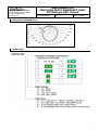
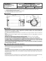
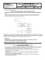
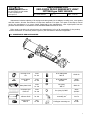
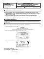
d.o.o.
10090 Zagreb, Medarska 69
tel. 049 222900, fax 049 426450
e-mail: [email protected]
www.tepex.hr
USER MANUAL FOR
EXPLOSION PROOF EMERGENCY LIGHT
FITTING type FLXE 118 LED
No: TEPEx.RS.016
Rev : 0
Date: 11.2012.
1. GENERAL SAFETY INSTRUCTIONS
WARNING
The user manual contain basic safety instructions to be observed during installation, operation
and maintenance of device, and for properly and safety run of the device according to its
performance data. Any damage may render explosion protection null and void. This manual
represents the most relevant information about the product. Adequate national laws and
regulations supplement it. Non-observance will endanger persons, plant and the environment.
The person in charge is required to secure its employment in the industrial unit. Every improper
or unofficial usage, as well as non-compliance with the rules of this manual, release the
manufacturer of all responsibilities.
Before assembly/commissioning
- Read through the operating instructions,
- Give adequate training to the assembly and operating personnel,
- Ensure that the contents of the operating instructions are fully understood by the personnel in charge,
- The national installation and assembly regulations (e.g. IEC/EN 60079-14) apply.
If you have questions:
- Contact the manufacturer
When operating the device:
- Ensure the operating instructions are made available the personnel in charge on location at all times,
- Observe these instructions, other working instructions and national safety regulations,
- Verify the implementation of safety instructions.
2. PURPOSE
Explosion proof emergency light fitting type FLXE 118 LED is designed to illuminate areas endangered by
flammable and explosive mixtures of gases and air, as well by presence of combustible dust, fibres or
flyings, in zones 1, 2, 21, 22, in accordance with standards IEC 60079-10.
The product is suitable for design of emergency-projects according to luminous and electrical requirements
of standards EN 1838:1999 and EN 50172:2004 as well as VDE 0108-100:2010.
3. CONFORMITY WITH STANDARDS
The product meets all requirements of EN 60598-1:2008/A11:2009, EN 60598-2-22:1998, EN 62034:2012,
EN 62031:2008 and EN 62471:2008 and all related standards. The product is developed, manufactured and
tested in accordance with EN ISO 9001:2008 and EN 80079-34:2011.
The regulations and standards it complies with include:
- Directive 94/9 EC - ATEX
EN 60079-0:2009
EN 60079-1:2007
EN 60079:31:2009
- Directive 2004/108 EC - Elektromagnetic compatibility
EN 55015:2006/A1:2007/A2:2009
EN 61547:2009
EN 61000-3-2:2006/A1:2009/A2:2009
- Directive 2002/95 EC - RoHS
1
d.o.o.
10090 Zagreb, Medarska 69
tel. 049 222900, fax 049 426450
e-mail: [email protected]
www.tepex.hr
USER MANUAL FOR
EXPLOSION PROOF EMERGENCY LIGHT
FITTING type FLXE 118 LED
No: TEPEx.RS.016
Rev : 0
Date: 11.2012.
4. DEGREE OF PROTECTION AND TECHNICAL DATA
Certificate
Device protection and explosion
protection:
Operating temperature range:
Degree of protection:
Impact resistance:
Class of protection:
Rated operational voltage:
Rated current:
Power factor:
Rated autonomy:
Rated power and type of luminaire:
Measuring luminous flux(power and
batery operation):
Temperatura boje svjetlosti:
Color rendering index (CRI):
Average rated life of LED:
Visibility (EN 1838)
Operation efficiency:
Change-over
Battery operation:
Mains supply operation:
Battery:
Battery life:
Charging time:
Connection terminals:
Storage:
Ex-Agency Croatia
CESI
II 2G Ex d IIC T6 Gb
II 2D Ex tb IIIC T80°C Db
-20oC : +50oC
IP66 / IP67, EN 60529:1991/A1:2000
IK 08 , EN 62262:2002
I (protective earthing)
24 - 240 V AC/DC ± 10 % (see table of version)
10 VA
cos φ > 0,95
3 hours
LED 2 x 1,2 W
chip-on-board tehnology
200 lm
6500 K
>70
≥50 000 hours
22 m
~ 80 %
U < 0,8 Un for more than 0,5 seconds
U > 0,9 Un for more than 1 second
Ni-Mh Saft VHT 3,6 V/2 Ah, IEC 61951-2:2011, builtin lighting, microprocessor controlled charging,
discharging and battery monitoring
min. 2000 charging cycles or min. 4 years in nominal
operating conditions
15 hours (12 hours > 90% nominal autonomy),
continous battery recharge
FLXE 118 LED/. 0, FLXE 118 LED/. 1
- snap-in terminals for mains supply L, L´, N, PE,
TEST, RESET, 2,5 mm2 max. per terminal, solid,
stranded, flexible - sol(r), s(r), f
FLXE 118 LED/. 2, FLXE 118 LED/. 3
- screw terminals, of Ex de Adapter ADP, for mains
supply L, L´, N, PE as well as TEST and RESET
conectors; - 2,5mm2 max. per terminal, solid,
stranded, flexible - sol(r), s(r), f; nominal fastening
torque 1,2Nm;
- Ex e cable gland ISO 25 on Adapter ADP for cable
ø6-15mm; nominal fastening torque 2,5 Nm
- earthing terminal (external) (equipotential), 2 x
6mm2 max. per terminal, solid, stranded, flexible sol(r), s(r), f; nominal fastening torque 2,2 Nm
- max. 4 months on temperature +5oC : +25oC and
humidity 65 ± 5%,
- max. 1 month on temperature -20oC : +5oC or
+25oC : +70oC and humidity 65 ± 5 %
2
USER MANUAL FOR
EXPLOSION PROOF EMERGENCY LIGHT
FITTING type FLXE 118 LED
d.o.o.
10090 Zagreb, Medarska 69
tel. 049 222900, fax 049 426450
e-mail: [email protected]
www.tepex.hr
No: TEPEx.RS.016
Rev : 0
Date: 11.2012.
5. ISOCANDELA DIAGRAM [l/cd]
6. MODEL CODE
3
USER MANUAL FOR
EXPLOSION PROOF EMERGENCY LIGHT
FITTING type FLXE 118 LED
d.o.o.
10090 Zagreb, Medarska 69
tel. 049 222900, fax 049 426450
e-mail: [email protected]
www.tepex.hr
No: TEPEx.RS.016
Rev : 0
Date: 11.2012.
7. OPERATING MODES
The lamp can operate with two types of connection:
a) Maintained (Dauerschaltung)
The light fitting can be used for general and orientation lighting with mains power supply via L'
(installation switch). In case of voltage drop or an interruption in the mains power suply L, the light
fitting will continue to operate in battery-powered mode, regardless of the status of installation switch L'
(ON/OFF)..
b) Non maintained (Bereitschaftschaltung)
In case of voltage drop or an interruption in the mains power suply L, the light fitting will operate only in
battery-powered mode.
In both types of the connection in the presence of continuous phase L, it is possible to verify the correctness
of the emergency system by turning on the switch in the TEST circuit.
In both types of the connection in the presence or interruption of continuous phase L, regardless of the
status of the power supply L', it is possible to turn OFF the emergency lighting, by turning ON the switch in
the RESET circuit.
In case of an interruption in the mains power supply and then recovery of continuous phase L (L'), if the
installation switch is turned ON, the light fitting will work in operating mode powered by the mains power
supplay.
Max. 20 light fitting in line wiring can be connected per external switch. For larger numbers of
line wiring of TEST/RESET circuits and longer cabel lenghts, please consult the manufacturer.
The light fitting is equiped with an electronic set for emergency lighting self-monitoring function and status
signaling function. Self-monitoring is permanent. status signalisation is indicated with red and green
indicator LED when the light fitting does not work.
Constant green LED, indicates the optimal functionality of the emergency system and the nominal
autonomy, with batteries rated capacity within the rated ambient temperature. Batteries are permanently
charged in "trickle charge" mode.
Blinking green LED, indicates the functionality of the emergency system in non-nominal autonomy.
Autonomy is between 1 and 3 hours. Batteries are under charging phase with rated current.
Constant Red LED, indicates the dysfunction of the emergency system. Reasons for this may include some
of the following:
- batteries are empty. The lamp should be left on the main power supply. After a while the signalisation
will by itself transferr into green LED, blinking lights and emergency lighting will become functional
- Ex d cover isn't screwed completely. Screw until green LED appears, blinking lights and emergency
lighting becomes functional,
- connection is made incorrectly. Connection should be made according to the connection scheme
- batteries are old, permanently charged with rated current and are overheating. It is necessary to
replace the LED module, type FLXE 10-130,
- batteries are old and can't reach the required charging voltage and capacity. It is necessary to replace
the LED module, type FLXE 10-130,
- the fuse in the battery circuit Ø 5 x 20 mm 1.25 AT is faulty. Should be replaced.
Faulty fuse indicates the defective batteries. You will probably need to replace the LED module, type
FLXE 10-130,
- ambient temperature is outside specification limits.
Self-monitoring does not include a control of the LEDs validity.
Description of tag on the light fitting
, according to EN 60598-2-22:
X - emergency light fitting with built-in batteries
1 - emergency light fitting in a permanent connection
A - emergency light fitting with self-monitoring and status signaling function
4
USER MANUAL FOR
EXPLOSION PROOF EMERGENCY LIGHT
FITTING type FLXE 118 LED
d.o.o.
10090 Zagreb, Medarska 69
tel. 049 222900, fax 049 426450
e-mail: [email protected]
www.tepex.hr
No: TEPEx.RS.016
Rev : 0
Date: 11.2012.
B - emergency light fitting with main power supply option and automaticall turn ON after power return option
C - emergency light fitting with RESET function
D - emergency light fitting for use in areas with special hazards
180 - emergency light fitting with autonomy of 3 hours
8. DIMENSION
330
240±1
12
220±1
160±0,5
180±0,5
O13
9. MOUNTING
Fixing dimensions are shown in article 8. Light fitting is suitable for ceiling, wall or pole mounting, the
accessories are not included, see table in article 12. for the correct selection of the mounting accessories
and article 6. for self-adhesive pictograms.
Ex d cable glands and plugs are not an part of the delivery for the types FLXE LED 118/0. and FLXE LED
118/1.
Light fitting with TEST and RESET function must be equipped with two Ex d cable glands or two Ex de
adapter type ADP 24.
Light fitting type FLXE 118 LED/2. and FLXE 118 LED/3. is provided with one or two Ex de adapter.
Warning: Over tightening might damage the light fitting.
In case of use in an extremely aggressive atmosphere, please consult to the manufacturer.
The laight fitting is for functional reasons supplied with partially screwed cover. After mounting
and before putting the light fitting into operation, the cover must be fully screwed with the
enclosure and mechanically blocked with screw M5x10 (ISO 4027).
After opening the laight fitting, threded surfaca on cover and enclosure should be protected by
protective means for threads.
10. INSTALLING AND PUTTING INTO OPERATION
Network connection have to be performed through screwless terminals located on the LED module FLXE 10130 according to wiring diagram and technical data:
Maintained:
Permanent line has to be connected to the L(1) terminal. Phase conductor for power supply has to be
connected through installation switch to the L'(4) terminal. One should be careful that phase L and L' are the
same phase. Neutral conductor has to be connected to the N(3) terminal and protective earth conductor to
the PE(2) terminal.
Non maintained:
Permanent line has to be connected to the L(1) terminal. Neutral conductor has to be connected to the N(3)
terminal and protective earth conductor to the PE(2) terminal. L'(4) terminal is not connected.
5
d.o.o.
10090 Zagreb, Medarska 69
tel. 049 222900, fax 049 426450
e-mail: [email protected]
www.tepex.hr
USER MANUAL FOR
EXPLOSION PROOF EMERGENCY LIGHT
FITTING type FLXE 118 LED
No: TEPEx.RS.016
Rev : 0
Date: 11.2012.
External grounding, equipotential - IP is connected to an external terminal provided with a grounding
conductor 6 mm2 solid (r), s (r), f.
Label with a wiring diagram is on the LED module FLXE 10-130.
If the electrical connection is performed through Ex de adapter, internal wiring is done by the manufacturer.
The electrical connection to the terminals of adapter have to be performed according to wiring diagram
below.
“RESET” circuit is connected to the (5) and (6) terminals and “TEST” circuit to the (7) and (8) terminals.
In the case of parallel connection more than one RESET or TEST circuit one should be careful that the
terminals of the same polarity are always short-circuited.
Before putting into operation it’s necessary to check accuracy of installation and functionality of the lamp
according to this manual and other applicable regulations. Insulation resistance test should be performed between
the phase conductor L and protective earth conductor PE and between the neutral conductor N and protective
earth conductor PE. Test voltage is max. 1kV AC and test current is max. 10 mA.
Warning !
Do not carry out any testing between the phase conductor L and neutral conductor N.
Otherwise, the LED module in the lamp will be destroyed.
11. INSTALLING, CONTROL, MAINTENANCE AND REPAIR
Before each opening of the housing must be respected the warnings on the label:
Do not open when energized
After de-energizing delay ten minutes before opening
It is necessary to carry out inspections and maintenance of all components on which the explosion
protection depends in accordance to standards HRN EN 60079-17:2007 (EN 60079-17:2007/C1:2008),
general and special conditions of manufacturer and users regulations, in particular:
- the housing, all parts of housing, housing of adapter, the protective glass and the cover gasket are
completely without a rupture or damage,
- the housing is completely closed by its cover and that the mechanical blockage against selfopening
is carried out,
- the Ex d cable glands and plugs are installed by the instructions of the manufacturer and they are
tightened with torque regulated by manufacturer,
- the gland gasket and Ex de adapter housing gasket are undamaged, and lock nuts are tightened with
torque regulated by manufacturer.
6
d.o.o.
10090 Zagreb, Medarska 69
tel. 049 222900, fax 049 426450
e-mail: [email protected]
www.tepex.hr
USER MANUAL FOR
EXPLOSION PROOF EMERGENCY LIGHT
FITTING type FLXE 118 LED
No: TEPEx.RS.016
Rev : 0
Date: 11.2012.
Maintenance includes replacing of Ex d plugs and cable glands, Ex de adapter, housing cover, cover gasket
and LED module. All other interventions on lamp have attribute of a repair. The repair of the lamp is carried
out by the manufacturer or a person legally authorized by the manufacturer, with original parts from the
products documentation in accordance to the standards HRN EN 60079-19:2007.
If the repair is carried out by a third person, the manufacturer is free of all responsibility for the product,
and the declaration of conformity which is given by the manufacturer becomes insignificant.
12. SPARE PARTS AND ACCESSORIES
SKICA
DESCRIPTION
CODE
Housing cover
set
SKETCH
DESCRIPTION
CODE
FLXE
10-110
Ex d cable gland
ISO 20
SPUD 20
Cover gasket
FLXE
FLXE
10-120
Ex d cable gland
3/4"NPT
SPUD
3/4"NPT
Base plate FLXE
FLXE
10-130
Ex d plug
ISO 20
SPCD 20
Protective grid
FLXE set
FLXE
20-140
Ex d plug 3/4"NPT
SPCD
3/4"NPT
External
reflector FLXE
FLXE
20-150
FLXE wall/ceiling
mounting set
FLXE
20-170
Junction box
ADP 23
ADP
10-160
FLXE pipe mounting set
FLXE
20-180
7
USER MANUAL FOR
EXPLOSION PROOF EMERGENCY LIGHT
FITTING type FLXE 118 LED
d.o.o.
10090 Zagreb, Medarska 69
tel. 049 222900, fax 049 426450
e-mail: [email protected]
www.tepex.hr
No: TEPEx.RS.016
Rev : 0
Date: 11.2012.
13. RESPONSIBILITY AND AUTHORIZATION
This Manual represents the most relevant information about the product. Adequate national laws and regulations
supplement it. Production, usage, certification and supervision are determined at the national level with:
a) Regulations of Equipment and protective systems intended for use in potentially explosive atmospheres
(Official Gazette no. 34/10.)
b) Regulations of minimum requirements for safety and health protection of workers and technical
Inspection of facilities, equipment, installations and devices in potentially explosive atmospheres (Official
Gazette no. 39/06, 106/07.)
The responsible person shall ensure their implementation at the facility.
14. STORAGE AND TRANSPORT
Transport and storage is only allowed in the original packaging, on the way pointed out on the carton box.
15. MARKING
Explosion protected fluorescent lighting fitting, type FLXE 118/. . is labeled with:
- a warning label on the cover of the lamp:
WARNING
DO NOT OPEN WHEN ENERGIZED
AFTER DE-ENERGIZING DELAY TEN MINUTES BEFORE OPENING
- a label with a wiring diagram on the LED module FLXE 10-130:
- a label with technical data on the cover of the lamp:
1)
2)
data according to model code
manufacturer data : - production number,
- number of a single examination,
- date,
- responsible person
8