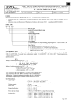
1
d.o.o.
10090 Zagreb, Medarska 69
tel. +385 49 222900, fax +385 49 426450
e-mail: [email protected]
www.tepex.hr
USER MANUAL FOR EXPLOSION PROTECTED
FLUORESCENT LIGHTING FITTING TYPE FLXE 118/..
Doc.No: TEPEx.RS.016
Ver : 0
Date: 31.08.2010.
PURPOSE
Explosion proof fluorescent lighting fitting type FLXE 118/.. with self-contained power supply is intended for use as emergency and
common lighting in industry areas:
- in areas endangered by flammable and explosive mixtures of gases and air, fumes of flammable liquids and air, or various combinations
between the two, in danger zones 1,2 in ordinance with standards IEC 60079-10/02,
- in areas endangered by explosive and flammable mixtures of dust and air in danger zones 21, 22 in ordinance with standards EN
50281-3/02.
MODEL CODE
FLXE 118/ . . .
base type description
description of the cable entry type:
- 0 - EEx d cable entry 3 x M20, ISO 965-1, ISO 965-3
- 1 - EEx d cable entry 3 x 3/4"NPT, ANSI/ASME B1.20.1
- 2 - EEx e indirect cable entry 1 x M25 (EEx de adapter)
emergency description (pictogram)
TYPE OF PROTECTION
The explosion-protection ensure "Flameproof enclosures" type of protection, utilizing "General requirements" according to EN
50018/00.+A1/02, EN 50014/97.+C1/98.+A1,A2/99. and the "Electrical apparatus protected by enclosures" type protection according to
EN 50281-1-1/98.
Apparatus category: II 2GD
Marking of explosion-protection:
- EEx d IIC T6, T 80ºC, IP 66/IP 67 - type FLXE 118/. 0 and FLXE 118/. 1
- EEx de IIC T6, T 80ºC, IP 66 - type FLXE 118/. 2
Degree of protection (IP Code): IP 66 / IP 67 in accordance with EN 60529+A1
Enviroment temperature: -20ºC ≤ TA ≤ +40ºC
Degree of protection (IK Code): IK 08 in accordance with EN 50102
Insulation class : I (protective earthing) in accordance with EN 61140
Electromagnetic compatibility: in accordance with the Directive 89/336 EEC, EN 55015, EN 61547
Tehnical data:
Rated voltage:
Rated power:
Power grid current at 230V:
Power and light source:
Lumen output:
- network grid power supply
- battery power supply
Rated autonomy:
Lumen output at the end of rated
autonomy:
Luminaire efficienty:
Voltage when passing from network
grid on to battery power supply:
Voltage when passing from battery
power on to network grid supply:
Battery:
Battery charging time:
Enviroment temperature:
(in all work conditions)
Cable entries:
230 - 240 V / 50 - 60 Hz
21 W
0,09 A
18 W fluorescent compact tube TC-L, base 2G11,
electronic ballast with integrated module for emergency lighting
750 lm (DULUX L 18W/840), Ra = 1B
~ 500 lm
3 hours
ØE/ØN = 75%
~ 80 %
U < 178 V duration more than 0,5 seconds
U > 195 V (0,9 Un) duration more than 1 second
Ni-Cd 6V/4Ah, build in lamp, microprocesor controled charging, decharging and
control of battery
24 hours ( 20 hours > 90% rated autonomy )
-15ºC to +40ºC
-FLXE 118/. 0 - 3 x M20 in accordance with ISO 965-1, ISO 965-3, without
EEx d cable glands and stopping plugs
-FLXE 118/. 1 - 3 x 3/4"NPT in accordance with ANSI/ASME B1.20.1, without
EEx d cable glands and stopping plugs
-FLXE 118/. 2 - 3 x M20 in accordance with ISO 965-1, ISO 965-3, with one
EEx de adapter for cable gland, ¯v 6-15 mm, and one EEx d stopping plug M20
1
Connection terminals:
FLXE 118/. 0 , FLXE 118/. 1:
- L1, L2, N, PE, S1,
2 x 4mm2 max. / clamp - solid, stranded
passtrough wireing is possible,
- clamp for external earthing
2 x 6mm2 max. - solid, stranded, tightening torque for screw clamp 2,2 Nm.
FLXE 118/. 2:
- clamps in EEx de adapter for connection L1, L2, N, PE, 2,5mm2 max. / clamp solid, stranded; tightening torque for clamp screw 1,2 Nm; EEx e cable gland M25 for
cables ¯v 6-15 mm; tightening torque for gland screw 2,5 Nm,
- clamp for external earthing
2 x 6mm2 max. - solid, stranded, tightening torque for screw clamp 2,2 Nm
Work mode:
Network grid power supply – common lighting – Network connection have to be performed according to scheme on electronic module
- N, L1, L2, PE. Switch phase connection have to be performed through switch on L2 clamp. Phase connection for power supply of
electronic module have to be performed through N, L1, PE clamps.
Battery supply – emergency lighting – three types of connection are possible:
a) maintained (permanent, Dauerschaltung)
In case of network grid power supply failure, no matter of position of switch in L' circuit (network grid power supply is switched on
or off), luminaire is working in emergency mode. Network connection have to be performed according to scheme - N, L1, L2, PE.
Contacts S1 have to be connected with jumper bar on connection plug clamp in luminaire (performed by manufacturer).
b) permanent connection with possibility of disconnecting emergency lighting
Just like a) only that contacts S1 lead outside the lamp (remote switch). With switch is possible to turn on or off the emergency
lighting if network grid power supply occur.
c) non maintained (non permanent, Bereitschaftschaltung)
Luminaire doesn't work on network grid power supply, only with battery supply in case of network grid power supply failure.
Network connection have to be performed according to scheme - N, L1, PE – do not connect L2. Contacts S1 have to be connected
with jumper bar on connection plug clamp in luminaire (performed by manufacturer).
ELECTRONIC MODULE
NLE
S1
N
L1
L2
PE
N
L
L'
1
2
3
L
4
Selfcontrol of rightness emergency lighting
In time periods specified by manufacturer, when network grid power supply is present, electronic module automaticaly execute
selfcontrol of rightness functionality of emergency lighting and battery capacity.
Functionality test
Assumption for test
Continuance
Repetition period
Test signalization
Test object
Mulfunction signalization
Procedure when the tube is defected
Procedure when the battery is defected
Capacity test
1 hour of continues network grid
48 hours of continues network
power supply
grid power supply
1 minute
2 hours
7 days
364 days
LED-signal: test functionality / capacity
functionality of light source (tube mulfunction)
functionality of battery (battery mulfunction)
LED-signal: tube mulfunction / battery mulfunction
test is finished,
test is finished, will be repeated
it won't happen again
again when mulfunction is
eliminated
test is finished, it won't happen again
2
Tube mulfunction:
Mulfunction will be signalized with LED diode imediatly after occuring. Normaly function of tube is possible. Removing of mulfunction
will cancel LED signal.
Battery mulfunction:
Mulfunction will be signalized with LED diode imediatly after occuring. Normaly function of battery is still possible in range of
acceptable parameters. Successfully conduct capacity test will cancel mulfunction signal.
Returning of electronic module in initail condition – delivery condition:
Returning assume setting of test functionality calendar on beginning and canceling mulfunction signal. For that purpose voltage on phase
connection clamps must be in interval less than 30 seconds cut off at least 3x with duration period of minimal 2 seconds. „RESET“
(returning on initail condition) will be cunduct for cca. 5 seconds. Next, like after first installing, electronic module automaticaly execute
functionality and capacity test .
LED signalization:
Event information is given by LED signal coding. Presentation priority, by more simultaneously events, is given in table.
Priority
01
02
03
04
05
Way of working
Description
RESET
battery mulfunction
tube mulfunction
functionality / capacity test
permanent battery charging
network grid
power supply
LED signal
ASSEMBLAGE AND REPLACING THE LIGHT SOURCE
The opening of the enclosure is exclusively allowed in a non-voltage state while respecting the warnings on the label.
The non-voltage state should be secured by shutting the voltage off on the main switch. Before opening the casing by screwing the lid, it
is necessary to unblock it mechanically by twisting the blockade screw M5x10 ISO 4027 on the lid. The electric connection is performed
by linking power supply cable on the plug on terminals on the base plate: L-phase conductor, L' – switch phase conductor from adapter
plug (depending of a luminaire type), N-neutral conductor, PE-protective grounding. The outer grounding, the equalization of potentials connect the IP to the outer terminal.
EEx d glands and plugs are not a part of the original products FLXE 118/.0 and FLXE 118/.1, and are secured by the user. During
installation, one must follow the instructions of the manufacturers of the glands and plugs. Type FLXE 118/.2 is equiped by
manufacturer with one EEx de M25 adapter, type ADP 24, for indirect cable connecting and one EEx d M20 plug.
The luminaire is using standard compact fluorescent tube 18W for 2G11 lampholder – OSRAM DULUX L 18W, PHILIPS MASTER
PL-L 18W.
After every opening of the lamp the screw joint should be protected by the “Baplex – INA d.d.” protective solution (manufacturer’s
recommendation).
The closing of the casing should be done by a reverse sequence of action.
A standard assembly of the luminaire is done on a vertical suspension over the eye bolt with ø13 mm hole on a casing. With the proper
equipment, assembly is possible on specific ways:
104
76
15
R6,5
28
2“(φ60)
R5
11,5
6
R6,5
R6,5
13
6
57
11,5
R6,5
41
37
13
41
2,5
Assembly kit for quick fixing FLX
2,5
Assembly kit for fixing 2” on tube (Ø60) FLX
Assembly kit for ceiling mounting FLX
CONTROL, MAINTENANCE AND REPAIR
3
It is necessary to conduct review and maintenance on all parts on which the explosion proof protection depends in accordance to
standards IEC 60079-17, general and individual demands of the manufacturer and the regulations of the user, and especially:
•
that all enclosures, all parts of the casing, adapter casing, the protective glass and the gasket of the cover are completely
without a crack or damage,
•
that the enclosure is completely closed by its cover and that the mechanical blockage against selfopening is carry out,
•
that the EEx d glands and the plugs, are installed by the instructions of the manufacturer and that they are tightened with
torque regulated by manufacturer,
•
that the gland gasket and EEx de adapter casing gasket are undamaged, and gland screw is tightened with torgue
regulated by manufacturer.
Maintenance presume replacing: EEx de adapter, EEx de adapter gasket, EEx d plug gasket, cover gasket, base plate with components,
and replacing fluorescent tube. All other interventions on luminaire have attribute of a repair. The repair of the lamp is done by the
manufacturer or a person legally authorized by the manufacturer, with original parts from the products documentation, and in accordance
to the IEC 60079-19 standards. If the repair is done by a third person, the manufacturer is free of all responsibility from the product, and
the declaration of conformity which is given by the manufacturer becomes insignificant.
SPARE PARTS AND ACCESSORIES
Spare parts:
•
Adapter ADP23 / ADP24, set
•
Casing and pressure nut gasket of adapter ADP23 / ADP24
•
EEx d plug M20, set
•
EEx d M20 plug gasket
•
Base plate FLXE with components
•
Compact fluorescent tube TC-L 18W
•
•
•
•
•
Accessories:
Protective grid FLX, set
External reflector FLX, set
Assembly kit for quick fixing FLX, set
Assembly kit for fixing 2” on tube (ø60) FLX, set
Assembly kit for ceiling mounting FLX, set
RESPONSIBILITY AND AUTHORIZATION
Responsibility and authorization are defined by the "Regulation on technical supervision over the electrical stations, installations and
equipment intended for usage in potentially explosive atmospheres" . This Manual represents the most relevant information about the
product. Adequate national laws and regulations supplement it. The person in charge is required to secure its employment in the
industrial unit. Every improper usage, as well as every unofficial restructuring, repair or restoration of the product, release the
manufacturer of all responsibilities.
STORAGE AND TRANSPORT
Transport and storage is only allowed in the original packaging, on the way pointed out on the carton box.
MARKING
Explosion-protected fluorescent lighting fitting, type FLXE 118/. . is labeled with:
a warning label on the cover of the lamp:
WARNING
DO NOT OPEN WHEN AN
EXPLOSIVE GAS AND DUST
ATMOSPHERE
IS PRESENT
labels containing technical and certification data on the cover of the lamp and on the base plate inside the lamp enclosure:
S
x
HR-10090 ZAGREB
FLXE 118/..1)230V 50Hz 18W TC-L 3h 06/AA1
II 2GD EEx..1) IIC T6 T80°C IP ..1)
HREx T 06.024 HRN EN 50014/18/..1)
..................................2)
1)
2)
data according to model code
manufacturer data : - production number,
- number of a single examination,
- date,
- responsible person.
4