1
TL03C -en
EN
Operating Instructions
Tml001
Tml - flux vector drive
0.25 kW… 2.2 kW
Contents
About these instructions.............................................................2
1
Safety information.................................................................3
1.1 Pictographs used in these instructions......................................................4
2
Technical data.......................................................................5
2.1 Standards and application conditions.......................................................5
2.2 Ratings.......................................................................................................6
3
Installation.............................................................................7
3.1 Mechanical installation..............................................................................7
3.1.1Dimensions and mounting.........................................................................7
3.2 Electrical installation..................................................................................8
3.2.1Installation according to EMC requirements.............................................8
3.2.2Fuses/cable cross-sections ......................................................................8
3.2.3Connection diagram..................................................................................9
3.2.4Control terminals......................................................................................10
4
Commissioning...................................................................11
4.1 Parameter setting.....................................................................................11
4.2 Electronic programming module (EPM)..................................................11
4.3 Parameter menu......................................................................................12
4.4 Vector mode............................................................................................19
4.4.1Vector speed and torque modes.............................................................19
4.4.2Enhanced V/Hz mode.............................................................................19
5 Troubleshooting and fault elimination..............................20
ENGLISH
About these instructions
This documentation applies to the Tml vector frequency inverter, and contains important technical data
and describes installation, operation, and commissioning.
These instructions are only valid for Tml frequency inverters with software rev 10 (see drive
nameplate).
Please read the instructions before commissioning.
V0006
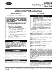
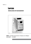
A Certifications
B Type
C Input Ratings
D Output Ratings
E Hardware Version
F Software Version
Scope of delivery
Important
• 1 Tml vector inverter (ETML...)
with EPM installed (see Section 4.2)
After receipt of the delivery, check immediately whether the items
delivered match the accompanying papers. Lenze does not accept
any liability for deficiencies claimed subsequently.
• 1 Operating Instructions
Claim
• visible transport damage immediately to the forwarder.
• visible deficiencies/incompleteness immediately to your Lenze
representative.
© 2004 Lenze AG
No part of this documentation may be copied or made available to third parties without the explicit written approval of
Lenze AG.
All information given in this documentation has been carefully selected and tested for compliance with the hardware and
software described. Nevertheless, discrepancies cannot be ruled out. We do not accept any responsibility nor liability for
damages that may occur. Any necessary corrections will be implemented in subsequent editions.
ENGLISH
Safety information
1
Safety information
General
Some parts of Lenze controllers (frequency inverters, servo inverters, DC controllers) can be live,
moving and rotating. Some surfaces can be hot.
Non-authorized removal of the required cover, inappropriate use, and incorrect installation or operation
creates the risk of severe injury to personnel or damage to equipment.
All operations concerning transport, installation, and commissioning as well as maintenance must
be carried out by qualified, skilled personnel (IEC 364 and CENELEC HD 384 or DIN VDE 0100 and
IEC report 664 or DIN VDE0110 and national regulations for the prevention of accidents must be
observed).
According to this basic safety information, qualified skilled personnel are persons who are familiar with
the installation, assembly, commissioning, and operation of the product and who have the qualifications
necessary for their occupation.
Application as directed
Drive controllers are components which are designed for installation in electrical systems or machinery.
They are not to be used as appliances. They are intended exclusively for professional and commercial
purposes according to EN 61000-3-2. The documentation includes information on compliance with
the EN 61000-3-2.
When installing the drive controllers in machines, commissioning (i.e. the starting of operation as
directed) is prohibited until it is proven that the machine complies with the regulations of the EC Directive
98/37/EC (Machinery Directive); EN 60204 must be observed.
Commissioning (i.e. starting of operation as directed) is only allowed when there is compliance with
the EMC Directive (89/336/EEC).
The drive controllers meet the requirements of the Low Voltage Directive 73/23/EEC. The harmonised
standards of the series EN 50178/DIN VDE 0160 apply to the controllers.
Note: The availability of controllers is restricted according to EN 61800-3.These products can cause
radio interference in residential areas. In this case, special measures can be necessary.
Installation
Ensure proper handling and avoid excessive mechanical stress. Do not bend any components and
do not change any insulation distances during transport or handling. Do not touch any electronic
components and contacts.
Controllers contain electrostatically sensitive components, which can easily be damaged by inappropriate
handling. Do not damage or destroy any electrical components since this might endanger your
health!
Electrical connection
When working on live drive controllers, applicable national regulations for the prevention of accidents
(e.g. VBG 4) must be observed.
The electrical installation must be carried out according to the appropriate regulations (e.g. cable crosssections, fuses, PE connection). Additional information can be obtained from the documentation.
The documentation contains information about installation in compliance with EMC (shielding, grounding,
filters and cables). These notes must also be observed for CE-marked controllers.
The manufacturer of the system or machine is responsible for compliance with the required limit values
demanded by EMC legislation.
ENGLISH
Safety information
Operation
Systems including controllers must be equipped with additional monitoring and protection devices
according to the corresponding standards (e.g. technical equipment, regulations for prevention
of accidents, etc.). You are allowed to adapt the controller to your application as described in the
documentation.
WARNING!
• After the controller has been disconnected from the supply voltage, live components
and power connection must not be touched immediately, since capacitors could be
charged. Please observe the corresponding notes on the controller.
• Do not continuously cycle input power to the controller more than once every three
minutes.
• Please close all protective covers and doors during operation.
Warnings!
• Suitable for use on a circuit capable of delivering not more than 5000 rms
symmetrical amperes, 240 V maximum (240 V devices) or 500 V maximum
(400/500 V devices) respectively
• Use minimum 75 °C copper wire only.
• Shall be installed in a pollution degree 2 macro-environment.
Note for UL approved system with integrated controllers
UL warnings are notes which apply to UL systems. The documentation contains special information
about UL.
1.1
Pictographs used in these instructions
Pictograph
Signal word
WARNING!
Meaning
Impending or possible danger
for persons
Death or injury
Possible damage to equipment
Damage to drive system or its
surroundings
Useful tip: If observed, it will
make using the drive easier
Note
Consequences if ignored
ENGLISH
Technical data
2
Technical data
2.1
Standards and application conditions
Conformity
CE
Low Voltage Directive (73/23/EEC)
Approvals
UL 508C
Underwriters Laboratories - Power Conversion Equipment
Max. permissible motor cable
length (1)
shielded:
50 m (low-capacitance)
Input voltage phase imbalance
< 2%
unshielded:100 m
Humidity
< 95% non-condensing
Output frequency
0...240 Hz
Environmental conditions
Class 3K3 to EN 50178
Temperature range
Installation height
Transport
-25 … +70 °C
Storage
-20 … +70 °C
Operation
0 … +55 °C (with 2.5 %/°C current derating above +40 °C)
0 … 4000 m a.m.s.l. (with 5 %/1000 m current derating above 1000 m
a.m.s.l.)
Vibration resistance
acceleration resistant up to 0.7 g
Earth leakage current (EN 50178)
> 3.5 mA to PE
Enclosure (EN 60529)
IP 20
Protection measures against
short circuit, earth fault, overvoltage, motor stalling, motor overload
Operation in public supply networks
(Limitation of harmonic currents
according to EN 61000-3-2)
Total power
connected to
the mains
< 0.5 kW
0.5 … 1 kW
> 1 kW
Compliance with the requirements (2)
With mains choke
With active filter (in preparation)
Without additional measures
(1) For compliance with EMC regulations, the permissible cable lengths may change.
(2) The additional measures described only ensure that the controllers meet the requirements of the EN 61000-3-2.
The machine/system manufacturer is responsible for the compliance with the regulations of the machine!
ENGLISH
Technical data
2.2 Ratings
Mains
Type
ETML251X2SFA
ETML371X2SFA
ETML551X2SFA
ETML751X2SFA
ETML112X2SFA
ETML152X2SFA
ETML222X2SFA
Power
[kW]
0.25
0.37
0.55
0.75
1.1
1.5
2.2
Output Current
Imax for 60 s
Current
[A]
[A] (1)
[A] (2)
[A] (1)
[A] (2)
1/N/PE 230 V
(180 V -0%…264 V +0%)
50/60 Hz
(48 Hz -0%…62 Hz +0%)
3.4
5.0
6.0
9.2
12.0
16.0
21
1.7
2.4
3.2
4.2
6.0
7.0
9.6
1.6
2.2
2.9
3.9
5.5
6.4
8.8
2.6
3.6
4.8
6.3
9.0
10.5
14.4
2.4
3.3
4.4
5.8
8.3
9.6
13.2
(1) For rated mains voltage and carrier frequencies 4, 6, and 8 kHz
(2) For rated mains voltage and carrier frequency 10 kHz
IN
Voltage, frequency
ENGLISH
Installation
3
Installation
3.1
Mechanical installation
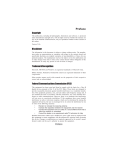
3.1.1
Dimensions and mounting
Tml002
a
[mm]
a1
[mm]
b
[mm]
b1
[mm]
b2
[mm]
c
[mm]
s1
[mm]
s2
[mm]
m
[kg]
ETML251X2SFA
ETML371X2SFA
93
84
146
128
17
83
15
50
0.5
ETML551X2SFA
ETML751X2SFA
93
84
146
128
17
92
15
50
0.6
ETML112X2SFA
ETML152X2SFA
114
105
146
128
17
124
15
50
1.2
ETML222X2SFA
114
105
146
128
17
140
15
50
1.4
Type
WARNING!
Drives must not be installed where subjected to adverse environmental conditions
such as: combustible, oily, or hazardous vapors or dust; excessive moisture; excessive
vibration or excessive temperatures. Contact Lenze for more information.
ENGLISH
Installation
3.2
Electrical installation
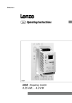
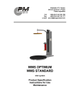
3.2.1
Installation according to EMC requirements
EMC
Compliance with EN 61800-3/A11
Noise emission
Drive models ending in the suffix “SFA” are in compliance with limit value class A
according to EN 55011 if installed in a control cabinet and with a motor cable not
longer than 10m.
B
A Screen clamps
C
B Control cable
D
A
C Low-capacitance motor cable
(core/core < 75 pF/m, core/screen < 150 pF/m)
D Electrically conductive mounting plate
Tml005
3.2.2
Fuses/cable cross-sections
Type
ETML251X2SFA
ETML371X2SFA
ETML551X2SFA
(1)
Installation to EN 60204-1
Miniature
L1, L2, L3,
Fuse
circuit
PE [mm²]
breaker
M10 A
C10 A
1.5
Installation to UL
Fuse (3)
L1, L2, L3,
PE [AWG]
10 A
14
ETML751X2SFA
M16 A
C16 A
2.5
15 A
14
ETML112X2SFA
M20 A
C20 A
2.5
20 A
12
ETML152X2SFA
M25 A
C25 A
2.5
25 A
12
ETML222X2SFA
M30 A
C30 A
4.0
30 A
10
E.l.c.b.(2)
> 30 mA
(1) Observe the applicable local regulations
(2) Pulse-current or universal-current sensitive earth leakage circuit breaker
(3) UL Class CC or T fast-acting current-limiting type fuses, 200,000 AIC, required. Bussman KTK-R, JJN, JJS, or equivalent
Observe the following when using E.l.c.b:
• Installation of E.l.c.b only between supplying mains and controller.
• The E.l.c.b can be activated by:
- capacitive leakage currents between the cable screens during operation (especially with long,
screened motor cables)
- connecting several controllers to the mains at the same time
- RFI filters
ENGLISH
Installation
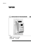
3.2.3
Connection diagram
Tml003
WARNING!
• Hazard of electrical shock! Circuit potentials are up to 230 VAC above earth
ground. Capacitors retain charge after power is removed. Disconnect power
and wait until the voltage between B+ and B- is 0 VDC before servicing the
drive.
• Do not connect mains power to the output terminals (U,V,W)! Severe damage
to the drive will result.
• Do not cycle mains power more than once every three minutes. Damage to
the drive will result.
ENGLISH
Installation
Terminal
Control terminals
Data for control connections (printed in bold = Lenze setting)
7
Reference common
8
Analog input
0 … 10 V (changeable under C34)
input resistance: >50 kΩ
(with current signal: 250 Ω)
9
Internal DC supply for setpoint potentiometer
+10 V, max. 10 mA
20
Internal DC supply for digital inputs
+12 V, max. 20 mA
28
Digital input Start/Stop
LOW = Stop; HIGH = Run Enable
input resistance = 3.3 kΩ
E1
Digital input configurable with CE1
Activate fixed setpoint 1 (JOG1)
HIGH = JOG1 active
E2
Digital input configurable with CE2
Activate fixed setpoint 2 (JOG2)
HIGH = JOG2 active
E3
Digital input configurable with CE3
Activate DC injection brake (DCB)
HIGH = DCB active
Relay output (N.O. contact)
configurable with C08
Fault (TRIP)
AC 250V / 3A
DC 24V / 2A ... 240V / 0.22A
Both HIGH = JOG3 active
K14
K12
Ri = 3.3 kΩ
3.2.4
LOW = 0 … +3 V, HIGH = +12 … +30 V
Protection against contact
• All terminals have a basic isolation (single insulating distance)
• Protection against contact can only be ensured by additional measures (i.e. double insulation)
10
ENGLISH
Commissioning
4
Commissioning
4.1
Parameter setting
Status/fault messages
Change parameters
Tml004
Note
If the password function is enabled, the password must be entered into C00 to access
the parameters. C00 will not appear unless the password function is enabled. See
C94.
Tmd007
4.2
Electronic programming module (EPM)
The EPM contains the controller’s memory. Whenever parameter settings are changed,
the values are stored in the EPM. It can be removed, but must be installed for the
controller to operate (a missing EPM will trigger an F1 fault). The controller ships with
protective tape over the EPM that can be removed after installation.
An optional EPM Programmer (model EEPM1RA) is available that allows: the controller to be programmed
without power; OEM settings to be default settings; fast copying of EPMs when multiple controllers
require identical settings. It can also store up to 60 custom parameter files for even faster controller
programming.
ENGLISH
11
Commissioning
4.3
Parameter menu
Code
No.
Possible Settings
Name
1
IMPORTANT
Lenze Selection
Password entry
0
0
Setpoint and control
source
0
Setpoint source:
999
Visible only when password is active
(see C94)
Control configuration:
0
Analog input (terminal 8; see C34)
1
Code c40 / Code C47
2
Analog input (terminal 8; see C34)
3
Code c40 / Code C47
4
Analog input (terminal 8; see C34)
5
Code c40 / Code C47
6
Analog input (terminal 8; see C34)
7
Code c40 / Code C47
Control = terminals
Programming = keypad
Control = terminals
Programming = remote keypad
Monitoring = remote keypad
Control = remote keypad
Programming = remote keypad
Monitoring = remote keypad
Note
• When C01 = 1, 3, 5, or 7 and C14 = 0...4, 6, 7, use c40 for speed setpoint
• When C01 = 1, 3, 5, or 7 and C14 = 5, use C47 for torque setpoint
• When C01 = 4...7, terminals E2 and E3 must be used for the remote keypad,
selections made for CE2 and CE3 will be ignored.
Load Lenze setting
0
No action/loading complete
• C02 = 1, 2, 3 only possible with
1
Load 50 Hz Lenze settings
2
Load 60 Hz Lenze settings
or
• C02 = 2 : C11, C15 and C89 = 60
Hz and C87 = 1750RPM
3
Load OEM settings (if present)
WARNING!
C02 = 1...3 overwrites all settings! TRIP circuitry may be disabled! Check codes CE1...
CE3.
12
ENGLISH
Commissioning
Code
No.
Possible Settings
Name
Configuration Digital input E1
Configuration Digital input E2
IMPORTANT
Lenze Selection
1
2
1
Activate fixed setpoint 1 (JOG1)
2
Activate fixed setpoint 2 (JOG2)
3
DC braking (DCB)
see also C36
4
Direction of rotation
LOW = CW rotation
HIGH = CCW rotation
5
Quick stop
Controlled deceleration to standstill,
active LOW; Set decel rate in C13
or c03
6
CW rotation
7
CCW rotation
CW rotation = LOW and CCW rotation
= LOW: Quick stop; Open-circuit
protected
8
9
UP (setpoint ramp-up)
DOWN (setpoint ramp-down)
UP = LOW and DOWN = LOW: Quick
stop; Use momentary NC contacts
10 TRIP set
Configuration Digital input/output E3
3
Activate JOG3: Both terminals = HIGH
(motor
Active LOW, triggers
coasts to standstill)
NOTE: NC thermal contact from the
motor can be used to trigger this input
11 TRIP reset
see also c70
12 Accel/decel 2
see c01 and c03
1…12 (same as above)
•1…12 configures terminal E3 as an
input.
•20…29 configures terminal E3 as a
current-sourcing (PNP) output rated
12 VDC / 50 mA
13...19 (reserved)
20
21
22
23
24
25
26
27
28
Ready
Fault
Motor is running
Motor is running - CW rotation
Motor is running - CCW rotation
Output frequency = 0Hz
Frequency setpoint reached
Frequency threshold (C17) exceeded
Current limit (motor or generator mode)
reached
29 Dynamic braking
Note
A C fault will occur under the following conditions:
• E1...E3 settings are duplicated (each setting can only be used once)
• One input is set to UP and another is not set to DOWN, or vice-versa
• When C01 = 4...7, terminals E2 and E3 must be used for the remote keypad, selections
made for CE2 and CE3 will be ignored.
ENGLISH
13
Commissioning
Code
No.
Possible Settings
Name
Configuration - Relay
output (terminals K14
and K12
1
IMPORTANT
Lenze Selection
1
Relay is energized if
0
1
2
3
4
5
6
7
8
Ready
Fault
Motor is running
Motor is running - CW rotation
Motor is running - CCW rotation
Output frequency = 0Hz
Frequency setpoint reached
Frequency threshold (C17) exceeded
Current limit (motor or generator mode)
reached
Minimum output
frequency
0.0
0.0
{Hz}240
• Output frequency at 0% analog
setpoint
• C10 not active for fixed setpoints or
setpoint selection via c40
Maximum output
frequency
50.0
7.5
{Hz}240
• Output frequency at 100% analog
setpoint
• C11 is never exceeded
WARNING!
Consult motor/machine manufacturer before operating above rated frequency.
Overspeeding the motor/machine may cause damage to equipment and injury to
personnel!
2
Acceleration time 1
5.0
0.0
{s}
999
Deceleration time 1
5.0
0.0
{s}
999
Operating Mode
2
• C12 = frequency change
0 Hz...C11
• C13 = frequency change
C11...0 Hz
• For S-ramp accel/decel, adjust c82
0
Linear characteristic with
Auto-Boost
• Linear characteristic: for standard
applications
• Square-law characteristic: for fans
and pumps with square-law load
characteristic
• Auto boost: load-dependent output
voltage for low-loss operation
1
Square-law characteristic with
Auto-Boost
2
Linear characteristic with constant
Vmin boost
3
Square-law characteristic with
constant Vmin boost
4
Vector speed control
• Vector speed control: for singlemotor applications requiring higher
starting torque and better speed
regulation
5
Vector torque control
• Vector torque control: for singlemotor applications requiring torque
control independent of speed
6
Enhanced linear characteristic
with Auto-Boost
7
Enhanced linear characteristic with
constant Vmin boost
• Enhanced: for single or multiple
motor applications that require better
performance than settings 0...3, but
cannot operate in vector mode
Note
• Settings 4...7 require Motor Calibration using c48
• Settings 4 and 5 require proper setting of C86...C91 prior to calibration
• Settings 6 and 7 require proper setting of C88...C90 prior to calibration
14
ENGLISH
Commissioning
Code
No.
1
Possible Settings
Name
V/f reference point
IMPORTANT
Lenze Selection
50.0
25.0
{Hz}
999
Set the rated motor frequency (nameplate)
for standard applications
C1
Vmin boost
(optimization of torque
behavior)
0.0
{%}
40.0
C16 not active in Vector mode (see C14)
Set after commissioning: The unloaded motor
should run at slip frequency (approx. 5 Hz),
increase C16 until motor current (C54) = 0.8 x
rated motor current
C1
Frequency threshold
(Qmin)
C1
Chopper frequency
0.0
2
0.0
{Hz}240
0
4 kHz
1
6 kHz
2
8 kHz
smd006
See C08 selection 7, and CE3
selection 27
• As chopper frequency is increased,
motor noise is decreased
• Observe derating in Section 2.2
• C18 = 1, 2, 3: Automatic derating to
4 kHz at 1.2 x IN
310 kHz
C
Slip compensation
0.0
0.0
{%}
40.0
Change C21 until the motor speed no
longer changes between no load and
maximum load
{%}200
• When the limit value is reached,
either the acceleration time
increases or the output frequency
decreases
• When c73 = 0, max setting is 167%
C21 not active in Vector mode (see C14)
Current limit
200
30
Reference: Tml rated output current
Accel boost
Configuration analog input
0.0
0
0.0
{%}20.0
0
0...10 V
1
0...5 V
2
Reserved
3
0...20 mA
4
4...20 mA
5
4...20 mA monitored
Accel boost is only active during
acceleration
• With 250 W resistance between
terminals 7 and 8
• C34 = 5 will trigger 5d5 fault if signal
falls below 2 mA
Voltage - DC injection
brake (DCB)
4.0
0.0
{%}
Fixed setpoint 1
(JOG 1)
20.0
0.0
{Hz}240
Lenze setting: active at E1 = HIGH
Fixed setpoint 2
(JOG 2)
30.0
0.0
{Hz}240
Lenze setting: active at E2 = HIGH
Fixed setpoint 3
(JOG 3)
40.0
0.0
{Hz}240
Lenze setting: active at E1 = HIGH and
E2 = HIGH
0.0
{Hz}240
Display: Setpoint via analog input,
function UP/DOWN
0
{%}
• When C14 = 5 and C01 = 1, 3, 5, 7
sets the torque setpoint
• When C14 = 5 and C01 = 0, 2, 4, 6
sets the torque range for C34
Frequency setpoint
Torque setpoint/range
100
ENGLISH
50.0
400
• See CE1...CE3 and c06
• Confirm motor suitability for use with
DC braking
15
Commissioning
Code
No.
Possible Settings
Name
IMPORTANT
Lenze Selection
Output frequency
0.0
{Hz}240
Display
Motor voltage
0
{V}
999
Display
DC bus voltage
0
{V}
999
Display
Motor current
0.0
{A}
400
Display
Controller load
0
{%}255
Display
Motor torque
0
{%}
Display: vector mode only
(C14 = 4, 5)
400
C6
Vector speed control
loop gain
30.0
0.0100
Optimizes dynamic performance in
vector mode
C6
Vector speed stability
30.0
0.0100
Optimizes steady-state speed stability
in vector mode
C7
Imax gain
0.25
0.0016.0
For most applications, there is no need
to change the Lenze settings (1)
7
Integral action time
Motor stator
resistance
65
0.00
Motor rated power
{ms}
9990
0.00
{W}
64.0
Will be automatically programmed
by c48 (1)
0.00
{kW}
99.9
• Set to motor nameplate kW
• Lenze setting = Tml rated kW
Motor rated speed
1390
300
{RPM}
Motor rated current
0.0
0.0
{A}
480
Set to motor nameplate current
Motor rated
frequency
50
10
{Hz}
999
Set to motor nameplate frequency
0
0
{V}
600
Set to motor nameplate voltage
Motor rated voltage
1
12
Motor cosine phi
0.80
65000
0.401.00
Set to motor nameplate speed
Set to motor power factor
Note
If motor power factor is not known, use the following formulas:
cos phi = motor Watts / (motor efficiency X C90 X C88 X 1.732)
cos phi = cos [ sin-1 (magnetizing current / motor current) ]
2
Motor stator
inductance
0.0
0.0
{mH}2000
• Indicates controller rating, format:
x.yz, or x.y.z
• x. = voltage (2. = 200/240V, 1~)
• yz or y.z = kW rating
Example:
2.0.3 = 200/240 V, 1~, 0.37 kW
Drive identification
User password
0
0
999
Changing from “0” (no password), value will
start at 763
(1)
16
When set to a value other than
0, must enter password at C00 to
access parameters
Display, format: x.yz
Software version
1
Will be automatically programmed
by c48 (1)
Acceleration time 2
5.0
0.0
{s}
999
Deceleration time 2
5.0
0.0
{s}
999
• Activated using CE1...CE3
• c01 = frequency change
0 Hz...C11
• c03 = frequency change
C11...0 Hz
• For S-ramp accel/decel, adjust c82
Changing these settings can adversely affect performance. Contact Lenze technical support prior to changing.
ENGLISH
Commissioning
Code
No.
Possible Settings
Name
IMPORTANT
Lenze Selection
Holding time automatic DC injection
brake (Auto-DCB)
0.0
I2t switch-off (thermal
motor monitoring)
100
0.0
{s} 999
0.0 = not active
999 = continuous brake
30
{%}100
100% = Tml rated output current
• Automatic motor braking after S P
by means of motor DC current for
the entire holding time (afterwards:
U, V, W inhibited)
• Confirm motor suitability for use with
DC braking
• Triggers 0C6 fault when motor
current exceeds c20 for too long
• Correct setting = (motor
nameplate current) / (Tml output
current rating) X 100%
• Example: motor = 6.4 amps
and Tml = 7.0 amps;
correct setting = 91%
(6.4 / 7.0 = 0.91 x 100% = 91%)
WARNING!
Maximum setting is rated motor current (see nameplate). Does not provide full motor
protection!
Frequency setpoint via
keys
Start condition
(with mains on)
0.0
1
0.0
{Hz}240
0
Start after LOW-HIGH change at
terminal 28
1
Auto start if terminal 28 = HIGH
2
Flying restart (auto start disabled)
3
Auto start if terminal 28 = HIGH,
with flying restart
Only active if C01 is set properly
(C01 = 1, 3, 5,7)
See also c43 and c70
WARNING!
Automatic starting/restarting may cause damage to equipment and/or injury to
personnel! Automatic starting/restarting should only be used on equipment that is
inaccessible to personnel.
Flying restart selection
Motor autocalibration
Mode selection for c61
0
0
0
0
Search range: C11...0 Hz
1
Search range: last frequency...0 Hz
0
Calibration not done
1
Calibration enabled
2
Calibration complete
0
Monitoring only
1
Monitoring and editing
Present status/error
status/error message
Last error
error message
If c42 = 2 or 3, the controller will start
the motor speed search at C11, or at
the last output frequency before the
fault, depending on the setting of c43
• If C14 = 4...7, motor calibration must
be performed, but C86...C91 must
be programmed first (see C14)
• If motor calibration is attempted
before programming C86...C91,
fault
triggers
to
c60 = 1 allows the keys
adjust speed setpoint (c40) while
monitoring c61
• Display
• Refer to Section 5 for explanation of
status and error messages
Last error but one
Last error but two
ENGLISH
17
Commissioning
Code
No.
Possible Settings
Name
7
Configuration TRIP
reset (error reset)
IMPORTANT
Lenze Selection
0
0
TRIP reset after LOW-HIGH change at
terminal 28, mains switching, or after
LOW-HIGH change at digital input “TRIP
reset”
1
Auto-TRIP reset
• Auto-TRIP reset after the time set in
c71
• More than 8 errors in 10 minutes will
trigger
fault
WARNING!
Automatic starting/restarting may cause damage to equipment and/or injury to
personnel! Automatic starting/restarting should only be used on equipment that
is inaccessible to personnel.
1
Auto-TRIP reset
delay
0.0
Input voltage
selection
0.0
{s}
0
Low (for 200 V input)
1
High (for 230 V input)
Operating time
counter
Display
Total time in status “Start”
Mains connection
time counter
Display
Total time of mains = on
60.0
• Lenze setting depends on C93
• During commissioning, confirm
correct setting based on mains
voltage
0...999 h: format xxx
1000...9999 h: format x.xx (x1000)
10000...99999 h: format xx.x (x1000)
S-ramp integration
time
0.0
0.0
L
Skip frequency 1
0.0
0.0
{Hz}240
L
Skip frequency 2
0.0
0.0
{Hz}240
L
Skip frequency
bandwidth
0.0
0.0
{Hz}10.0
{s}
Note
Bandwidth (Hz) = fs (Hz) + L28 (Hz)
See c70
50.0
• c82 = 0.0: Linear accel/decel ramp
• c82 > 0.0: Adjusts S-ramp curve for
smoother ramp
• L25 and L26 define the start of the
skip range
• L28 defines the bandwidth of the
skip range
fs = L25 or L26
Example: L25 = 18 Hz and L28 = 4 Hz; the bandwidth = 18...22 Hz
18
ENGLISH
Commissioning
4.4
Vector mode
Use the following procedures to select either Vector mode or Enhanced V/Hz mode. Enhanced V/Hz
mode should be used in the following cases:
1. Multiple motor applications
2. Where required motor data is not available (especially C91)
3. Where running in Vector mode causes unstable motor operation
4.4.1
1.
2.
3.
4.
5.
6.
Vector speed and torque modes
Connect the controller to the motor according to the diagram in Section 3.2.3.
Apply power to the controller.
Set C14 to 4 for Vector speed mode, or 5 for Vector torque mode.
Set C86...C91 according to the motor’s nameplate data.
Set c48 to 1 to enable the motor calibration function.
Make sure the motor is cold (rotor and windings are at room temperature of 20º to 25º C), and apply
a HIGH signal at terminal 28. The display will show
L for about 40 seconds. Once the calibration
is complete, the display will show
or 1 . Apply another HIGH signal to terminal 28 to actually
start the motor.
4.4.2
Enhanced V/Hz mode
Follow the procedure in 4.4.1 above, replacing steps 3 and 4 with those below:
3. Set C14 to 6 for Enhanced with Auto-Boost, or 7 for Enhanced with constant boost.
4. Set C88...C90 according to the motor’s nameplate data.
Note
• If the motor is hot when the motor calibration is performed, the controller will not
be able to achieve maximum performance.
• In Vector speed and Vector torque modes, if an attempt is made to start the
controller before performing the motor calibration, the controller will display
and the motor will not operate.
ENGLISH
19
Troubleshooting and fault elimination
5
Troubleshooting and fault elimination
Status
Present output frequency
e.g.
0
L
L
L
L
Cause
Stop (outputs U, V, W inhibited)
LOW signal at terminal 28
Set terminal 28 to HIGH
Inhibit (outputs U, V, W inhibited)
Controller is set up for remote
keypad (see C01)
Start the controller via the remote
keypad
Output frequency = 0 Hz
(outputs U, V, W inhibited)
Quick stop activated through digital
input
Deactivate Quick stop
Flying restart attempt
c42 = 2, 3
DC-injection brake active
DC-injection brake activated
• via digital input
• automatically
Deactivate DC-injection brake
• digital input = LOW
• automatically after holding time c06
has expired
Motor calibration is in process
c48 = 1 and terminal 28 = HIGH
Only perform the motor calibration
when C14 = 4...7
Current limit reached
Controllable overload
Automatically (see C22)
Undervoltage on DC bus
Mains voltage too low
Check mains voltage
Overvoltage on DC bus during
deceleration (warning)
Excessively short deceleration time
(C13, c03)
Automatically if overvoltage
< 1 s, , if overvoltage > 1 s
No access to code
Can only be changed when the control- Set terminal 28 to LOW
ler is in FF or nh
Remote keypad is active
Attempt to use buttons on front of
controller
Error
d
Remedy
Trouble free operation
Cause
A/D converter error
Buttons on front of controller are disabled when remote keypad is active
Remedy (1)
Please contact Lenze
Identification fault
C93 value stored on EPM does not
match controller model
Data on EPM not valid
Data error
Data not valid for controller
• Use EPM providing valid data
• Load Lenze setting
OEM data not valid
L
1
Automatic start inhibited
c42 = 0, 2
LOW-HIGH signal change at terminal 28
EPM error
EPM missing or defective
Power down and replace EPM
Digital inputs not
uniquely assigned
E1...E3 assigned with the same digital
signals
Each digital signal can only be used
once
Either just “UP” or “DOWN” used
Assign the missing digital signal to a
second terminal
Dynamic braking fault
Dynamic braking resistors are
overheating
Increase deceleration time
External error
Digital input “TRIP set” is active
Remove external error
Internal fault
Please contact Lenze
2 F
(1) The drive can only be restarted if the error message has been reset; see c70
20
ENGLISH
Troubleshooting and fault elimination
Error
0
Remedy (1)
Cause
Remote keypad fault
Remote keypad disconnected
Check remote keypad connections
Drive identification fault
Attempt was made to perform motor
calibration before setting C86...C91
Must set C86...C91 before performing
motor calibration (see c48)
Short-circuit or overload
Short-circuit
Find reason for short-circuit; check
motor cable
Excessive capacitive charging
current of the motor cable
Use shorter motor cables with lower
charging current
Acceleration time (C12, c01) too short
• Increase acceleration time
• Check controller selection
Defective motor cable
Check wiring
Internal fault in motor
Check motor
Frequent and long overload
Check controller selection
Grounded motor phase
Check motor/motor cable
Excessive capacitive charging
current of the motor cable
Use shorter motor cables with lower
charging current
Motor is thermally overloaded, due to:
• impermissable continuous current
• frequent or too long acceleration
processes
• Check controller selection
• Check setting of c20
Earth fault
Motor overload (I2t overload)
Controller overtemperature
Controller too hot inside
• Reduce controller load
• Improve cooling
Overvoltage on DC bus
Mains voltage too high
Check mains voltage
Excessively short deceleration time or
motor in generator mode
Increase deceleration time or use
dynamic braking option
Earth leakage on the motor side
Check motor/motor cable
(separate motor from controller)
Flying restart fault
Controller was unable to synchronize
with motor during restart attempt
Check motor/load
Faulty auto-TRIP reset
More than 8 errors in 10 minutes
Depends on the error
Loss of 4-20 mA reference
4-20 mA signal (terminal 8I) is below 2
mA (C34 = 5)
Check signal/signal wire
Single phase fault
A mains phase has been lost
Check mains voltage
(1) The drive can only be restarted if the error message has been reset; see c70
ENGLISH
21
Notes
22
AC Technology Corporation • 630 Douglas Street • Uxbridge, MA 01569 • USA
+1 (508) 278-9100