1
NAVI SAILOR VERSION 3.0.1
USER MANUAL
-i-
Installation checklist
1.
Install the hardware and make all the connections (Technical
Reference 2.1).
2.
3.
Install the software (Technical Reference 2.2/2. 3).
Check AUTOEXEC.BAT and CONFIG.SYS files
Reference 2.2).
4.
5.
Perform initial settings and run the NS (Technical Reference 3.1)
Run REGISTRY utility for the copy registration (Technical Reference
6.1).
Fill in Hardware Setup and Sensor Connection tables (Technical
Reference 6.2).
Put down the installation information on the first page of the User
Manual (User ID information).
6.
7.
8.
(Technical
Give general instructions on the handling of the system to the crew
- ii -
1 INTRODUCTION
INTRODUCTION
Page 2 of 210
1.1 General Notes and Warnings
1.1.1 Copyright
TRANSAS MARINE - is a registered Trademark of TRANSAS MARINE
(UK) Ltd.
NAVI-SAILOR - is a registered Trademark of video-plotters manufactured by TRANSAS MARINE.
Software copyright is stipulated in the company's Licensing Agreement
This Manual is a product of TRANSAS MARINE. No part of this manual
can be reproduced or transmitted without Company's written
permission.
1.1.2 Warnings for the Use of Transas Charts
Electronic charts manufactured by TRANSAS (TRANSAS format charts)
are not intended to substitute official nautical charts. TRANSAS charts
do not necessarily include the latest corrections and must not be used
otherwise than in combination with official paper charts.
It is a fully corrected paper chart, which is the primary source of
navigational information for the user. All the vessel control decisions
must be fully based on this chart's data.
The vessel's position displayed on the screen is only a graphic
presentation of the coordinates, their accuracy depending on the
position sensor connected.
Before planning the route using the NS video-plotter facilities, it is first
necessary to do it on the suitable scale paper charts, updated from the
latest Notices.
When transferring any data from a paper chart to the NS, pay special
attention to the possible difference between the paper chart datum and
WGS-84 datum used for the manufacture of TRANSAS charts
HOW TO USE THIS MANUAL
Page 3 of 210
1.2 How to Use this Manual
1.2.1 General Review and Purpose of the User Manual
This User Manual (hereinafter referred to as "Manual") deals with issues
connected with various aspects of using the NaviSailor software
(hereinafter referred to as the NS) in the process of its operation.
The Manual is so arranged that the user can promptly obtain information
on the procedures required for the solution of the problem he/she is faced
with, using the NS facilities.
The Manual consists of three parts:
1) "Introduction" containing some general notes and principles of using
this Manual.
2) "Purpose and General Description of NaviSailor Series Videoplotter". This part describes the capabilities and main operating
modes, as well as the information display principles and the NS
controls.
3) "User Work with the NaviSailor Software". This is the principal part of
the Manual, which contains the list of tasks, which can be performed
using the NS, and the procedures involved. To be able to use this
part of the Manual, the beginner should necessarily familiarize
him/herself with information provided in paragraph 'Data Required for
the Work with the Manual' (see below).
4) "Annex" to the Manual.
1.2.2 Data Required for the Work with the Manual
Information set forth in Part 3 of the Manual is presented in the form of
tables with the types of problems solved by the NS for headings Possible
options of their solutions are listed as follows:
• in numbered paragraphs of the section;
• with "•" symbol, when the alternative solutions are provided for the
given stage of the problem.
Navi Sailor ( version 3.0.1) User Manual
INTRODUCTION
Page 4 of 210
Keys and buttons used in the Manual for the descriptions of procedures:
• a key stroke on the keyboard is denoted by the key name in angle brackets, e. g., <+
> means pressing "+" key;
• <Alt>+ <F2> notation means that you should hold down the <Alt> key as you press
<F2> key;
• <Esc> notation means that you should press this key on the keyboard or the right
trackerball/mouse button. This key is used for canceling input of a typed value, or for
exiting into the NS main menu.
References to other paragraphs of the Manual and Notes:
• names of paragraphs listed in the 'Alphabetic List' are marked with apostrophes
and/or a capital letter in the tables;
• data input or parameter selection windows appearing in the Menu Area, as well as
various information windows and work with them are described in paragraph "Menu
Area";
• warnings and notes, which the reference is provided to in the table, are given at the
end of these tables.
An example of performing the prescribed procedures for the solution of problems in the NS is
given below:
3. 4. 6. (number of the paragraph from the list) Viewing Other Charts and Navigation
Areas (name of the paragraph - type of the problem to be solved)
The NS main menu function
involved
and/or
actions
required to be taken
1
CHART\Chart autoload
REVIEW
Indicator position
and/or the menu
NS display of the actions
executive key (on
performed and/or notes
the keyboard)
2
ON
<Enter>
3
To
turn
on
the
'Chart
Autoloading' mode
A 'Graphics Cursor' appears
The current chart is re-
Position the cursor on the
required chart fragment
<Enter>
drawn around the point
with the cursor's coordinates (centering)
Page 5 of 210
HOW TO USE THIS MANUAL
<Esc>
To exit from the viewing mode to the NS
main menu (see Menu Area’)
The following procedure should be used for performing this task:
•
•
•
•
•
•
•
•
•
use the 'Trackerball' or 'Keyboard' to position the cursor on CHART NS main menu
option and press the left trackerball button or <Enter> key;
in the submenu which will appear position the cursor on Chart autoload line and press
<Enter> again: the function's indicator is activated (turns orange);
move the 'Trackerball' up and down or use the cursor control keys on the 'Keyboard' to
set the required indicator position (ON) and press <Enter> again to turn on the chart
automatic loading mode. For more detailed information on this note see the paragraph
with this name (for which purpose you should look up the name of the paragraph in the
'Alphabetic List');
press <Esc> to exit into the NS main menu, position the cursor on REVIEW function
and press <Enter>: a Graphics Cursor appears (for the description of work with the
Graphics Cursor see the paragraph with this name Graphics Cursor);
use the trackerball to position the cursor on the chart fragment, which is required to be
reviewed and press <Enter> to center the current chart in the cursor's new position;
after completing the viewing, press <Esc> on the keyboard or the right trackerball
button to exit from this operation mode into the NS main menu (for the description of
the main menu see Menu Area paragraph).
In the above sample, in addition to what has been said, it is necessary to note the
following specific features of the data input and notations which you may come across
in following the procedures specified in such tables:
to set the required values (or those specified in column 2 of the table) in the functions'
literal indicators follow the procedure similar to that considered in a sample of ON/OFF
type indicator;
to set the required values in a function's digital indicator, it is necessary to activate this
indicator, then use trackerball (or the keyboard) to enter this value, then press <Enter>
to confirm the input;
Navi Sailor ( version 3.0.1) User Manual
INTRODUCTION
Page 6 of 210
• enter the coordinates (or dates) group by group. This means that after
entering each group of data (degrees, minutes, hemisphere) it is
necessary to press <Enter>. To cancel the input of a value at any stage
of its entry press <Esc> on the keyboard or press the right trackerball
button;
• if different functions can be used for performing an action, other possible
options (functions) are shown in parenthesis, e.g., SHIP\Primary
(Secondary) pos. notation means that at the user's option primary or
secondary vessel positioning can be selected.
1.2.3 Abbreviations Used in the Manual
App.
Appendix;
COG
Course Over Ground;
ECDIS
Electronic Chart Display and Information System;
ENC
Electronic Navigational Chart;
ERBL
Electronic Range and Bearing Line;
ERML
Expected Relative Motion Line;
ETA
Estimated Time of Arrival;
ETML
Expected True Motion Line;
GMT
Greenwich Mean Time;
GPS
Global Positioning System;
HO
Hydrographic Office;
NS
NaviSailor;
OS
Operating System;
RAM
Random Access Memory;
RML
Relative Motion Line;
SENC
System Electronic Navigational Chart;
STG
Speed To Go;
TML
XTE
True Motion Line;
Cross Track Error.
2 PURPOSE AND GENERAL DESCRIPTION OF
NAVISAILOR SERIES VIDEO-PLOTTER
PURPOSE AND GENERAL DESCRIPTION OF NAVISAILOR SERIES
VIDEO-PLOTTER
Page 8 of 210
2.1 NS Purpose and Principal Operation Modes
2.1.1 NS Purpose and Capabilities
NaviSailor series video-plotter is an electronic information and chart
system used with the aim of ensuring safe navigation.
•
•
•
•
•
•
•
The following functional capabilities are implemented in this software:
display of electronic vector and raster charts of different formats (up to 6
charts simultaneously);
data exchange with navigational sensors and external output devices
enabling the vessel position coordinates to be continuously obtained
and vessel controlled in accordance with changing navigational
situation;
route planning and drawing up the schedule of proceeding along this
route;
monitoring of approach to the dangers to navigation plotted on an
electronic vector chart or on a user chart created by the navigator;
trial maneuver for avoiding collision with other vessels displayed on the
NS screen in accordance with the information received from the ARPA;
solution of various kinds of navigational problems;
other capabilities described in this "User Manual".
2.1.2 Voyage Monitoring Mode
•
•
•
•
The Voyage Monitoring mode is a compulsory permanent mode, which is
run concurrently with other operation modes and ensures the following:
continuous vessel tracking;
automatic recording of the ownship's primary (principal) and secondary
(auxiliary or reference) tracks;
recording of ARPA targets' tracks;
keeping of the electronic ship's log;
NS PURPOSE AND PRINCIPAL OPERATION MODES
•
•
Page 9 of 210
obtaining information on the status of connected units;
graphically expressed summary assessment of the accuracy of vessel positioning and
plotting of objects on the chart;
• obtaining data on the vessel's position relative to the route;
• obtaining calculated vector of current in the vessel's position and summary drift vector
between COG/SOG - HDG/LOG;
• display of the current electronic chart scale;
• obtaining data from the auxiliary navigational sensors (depth, drift speed and direction,
weather condition parameters).
In addition, this mode ensures permanent monitoring of the vessel's position relative to the
objects listed below. In case of a dangerous approach to one of such objects the NS gives
off an appropriate alarm (see Setting the Parameters for Monitoring Safety at Sea and
Setting the Alarms in Voyage Monitoring Mode):
• safety contours;
• isolated dangers (see below) with depths less than the set one;
• special areas, available in the chart and/or updating database and located within a certain
range from the vessel (up to 10 miles).
The following vector chart objects are automatically assessed by the NS as isolated dangers:
• explosives;
• fish haven;
• foul ground;
• distinctive depth, submerged obstruction;
• obstruction, which covers and uncovers;
• oil/gas production platform;
• rock;
• shoal;
• well;
• shipwreck;
• shipwreck showing any portion of hull at the level of chart datum.
Navi Sailor ( version 3.0.1) User Manual
PURPOSE AND GENERAL DESCRIPTION OF NAVISAILOR SERIES
VIDEO-PLOTTER
Page 10 of 210
2.1.3 Navigation Mode
Navigation Mode is the principal mode of the NS operation, implies a
constant display of the ownship's position on the screen and is running
concurrently with the Voyage Monitoring Mode'.
•
•
•
•
•
•
•
•
•
In this mode the NS provides the navigator with the following data:
ownship's position (vessel's symbols and motion vector) and ownship's
tracks (from the primary and secondary positioning);
electronic chart with layers of automatic and manual correction, and
special user information;
secondary radar information (ARPA tracked targets) in the graphic form
with the relevant entries in the table;
targets acquired by the GPS-transponder system;
results of the ownship trial maneuver (with course and/or speed) in the
graphic form taking into account the vessel's dynamic characteristics
and summary drift, estimated position of the own ship and targets for
any moment of time (up to 24 minutes), parameters of dangerous
approach to the targets;
route planning on the chart;
display of sector lights in the color visible from the vessels' position with
the light visibility range taken into account (if the light cannot be seen the
lighthouse is shown in the gray color).
It should be noted that when some of the NS functions are activated, the
Navigation Mode is automatically exited from. To turn on or return to the
Navigation Mode use either of the following:
select AHEAD (in the NS main menu);
press <lnsert> or <F8> (on the keyboard).
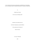
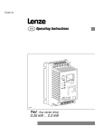
2.2 NS Screen
The NS screen includes three areas (see Fig. 2–1). The left hand part is
the Electronic Chart Area. Information Area and Menu Area take up the
right hand part. Sometimes when it is necessary to display some
additional information command, e. g., route plan waypoints, ship's log
entries, HELP text, etc. (as required by operator), a window opens up in
the left bottom part of the screen.
Page 11 of 210
NS SCREEN
At this time the chart is displayed in the top part of the screen.
Fig. 2–1 Screen Areas of Navi Sailor
2.2.1 Electronic Chart Area
This area may display the following information:
electronic charts (up to 6) covering the screen;
outlines and ID numbers of all the charts available in the collection
(for the displayed charts the frames are shown in a bold line and
numbers are in the bold type);
• numbered reference grid;
• additional information (such as temporary updating);
•
•
Navi Sailor ( version 3.0.1) User Manual
PURPOSE AND GENERAL DESCRIPTION OF NAVISAILOR SERIES
VIDEO-PLOTTER
Page 12 of 210
•
•
•
•
•
•
•
•
route plan with numbered waypoints;
ownship symbol - its primary position with a speed vector and the
secondary position;
display of the vessel's primary and secondary tracks;
ARPA cursor and ERBL;
positions and motion vectors of targets acquired by ARPA;
positions and motion vectors of targets acquired by the GPS
transponder system;
results of the trial maneuver;
current vectors.
The bottom right corner of the electronic chart displays an angle shaped
indicator, the sides of an angle formed by a thin line and a bold line.
Bold line is a graphic presentation of the maximum possible error of
plotting objects on TRANSAS chart. When a chart is displayed on the
scale of the original, the linear size of the error is taken to be 2 mm. As
the scale is growing, the linear dimensions of the indicator increase
showing to which extent the chart information can be relied on.
Thin line is a graphic presentation of a possible error of the vessel's
position sensor, which is taken to be equal to 70 m.
In the absence of charts suitable for loading, or with 'Chart Autoload'
OFF, No Data Area may appear on the NS screen: a gray colored field
with no information whatsoever. Such area will be automatically covered
with a chart during the screen regeneration if 'Chart Autoload' is turned
ON.
2.2.2 NS Information Area
The data displayed continuously in the Information area includes the following:
• indicator of the positioning methods (primary on the left and secondary on the
right). The following designations are possible:
GPS
DECCA
LRNN
OMGA
- GPS*;
-DECCA;
-LORAN-C*;
- OMEGA*;
NS SCREEN
ER
DR
NONE
Page 13 of 210
- positioning by ARPA reference target;
- dead reckoning;
- secondary positioning is switched off
!"Note: positioning methods marked with* (asterisk) may have a differential mode
(DGPS, DLRNC, DOMGA);
•
•
•
•
•
•
•
•
•
•
1.
•
•
•
•
•
indication that ARPA is connected;
status of the workstation operating in the network (displayed in the absence of alarm
messages);
TRANSAS MARINE trademark (displayed in the
absence of "POSITION DROPPED"
indicator meaning that the vessel symbol is not shown on the chart);
current time and date:
UTC
- Greenwich time and date,
LOCAL - ship's time and date;
displayed electronic chart number;
number or name of the user charts loaded in areas A and B;
vessel position coordinates and an offset indicator (if the offset is
taken into account). The indicator is an orange colored triangle
displayed to the left of coordinates which shows that the position
coordinates received from the currently used positioning system for
the primary vessel position, are corrected with the offset;
vessel's course and speed obtained from the positioning system (or entered manually),
gyro readings;
log readings.
There are 4 types of display in the NS Information Area.
Display System Mode presents general data on the sailing conditions
set (direction the vessel is drifting in);
drift (speed the vessel is drifting at);
depth from the sounder;
calculated safety contour;
calculated tidal rise in the closest reference point as of the current time;
Navi Sailor ( version 3.0.1) User Manual
PURPOSE AND GENERAL DESCRIPTION OF NAVISAILOR SERIES
VIDEO-PLOTTER
Page 14 of 210
•
•
2
calculated direction and speed of current in the vessel's position
time;
range and bearing to an acquired fixed object.
Display Route Mode presents data on the planned route
• route name;
• name and number of the next WP,
• vessel's course;
• cross track error with the indication of direction;
• bearing and range to the next waypoint;
• time to go to the next waypoint;
• estimated date and time of arrival in the next waypoint;
• course to steer to the next waypoint.
3 Display Pilot Mode presents data on the vessel's position relative
waypoint, calculated motion speed and ETA in the next waypoint:
•
•
•
•
•
4
•
•
as of the current
to
the
current
bearing to the current WP,
course to the next WP; number of the WP for
which ETA is set in the loaded schedule;
calculated speed to go for arrival in the WP for
which ETA is set in the loaded voyage schedule.
With this type of display, the following indications
may appear with this parameter:
STG without any marks (asterisk)
corresponds to the option when the ETA is set in the voyage schedule, whilst the
speeds on the route segments are calculated;
STG with an asterisk on the left means that the speed has been preset on one or
several route segments;
an asterisk on the right indicates that the speed has been preset in the voyage
schedule for the current route segment, whilst the displayed STG parameter value
shows the speed to go;
ETA in the set WP with the current speed (SOG) remaining unchanged,
time of arrival in the set WP according to the voyage schedule
Display Weather Mode presents data on the weather conditions
set (direction the vessel is drifting in);
drift (speed the vessel is drifting at);
Page 15 of 210
NS SCREEN
•
•
•
•
•
•
•
•
wind direction (with the side - L or R- indicated
for the relative wind and 360
degree
measurement for the true wind);
wind speed,
outside water temperature;
depth from the sounder;
indicator of the rudder blade position.
The middle part of the NS Information Area is intended for displaying the
results of limit speed calculations from the parameters set by the
navigator regardless of the data in the loaded voyage schedule (see 'Limit
Speed Calculations for Proceeding Along the Route'). The same part of
the Area contains information on the changes of range and bearing to an
objects tracked via TASK\OBJECT function (see Auxiliary NS Facilities
Used in the Voyage Monitoring Mode, paragraph 4)
The lower part of the Information Area displays:
length of speed vectors and the range in nautical miles across the
electronic chart display;
selected scale of the chart display;
and the following warnings:
- NOT RECOMM. SCALE or DANGEROUS SCALE if the scale of the
chart display on NS screen is up to 5 or over 5 fixed points
(respectively) larger than that of the paper original;
- LAYERS LOST if not all the Standard display information layers are
shown (see Turning ON/Off the Display of Various Information
Layers),
- LOOK UP BETTER CHART if there is a larger scale chart available
for the vessel position than that in use.
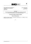
2.2.3 Menu Area
The NS Menu Area displays the names of functions
available for use at the moment. When the NS is
switched on, this area displays multilevel MAIN MENU.
Menu functions, which contain submenus, rather than
perform any specific actions, are called options. The
main menu has a structure shown in Fig. 2-2.
Navi Sailor ( version 3.0.1) User Manual
PURPOSE AND GENERAL DESCRIPTION OF NAVISAILOR SERIES
VIDEO-PLOTTER
Page 16 of 210
Fig. 2–2
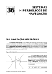
Page 17 of 210
NS SCREEN
Fig. 2–3
Navi Sailor ( version 3.0.1) User Manual
PURPOSE AND GENERAL DESCRIPTION OF NAVISAILOR SERIES
VIDEO-PLOTTER
Page 18 of 210
Fig. 2–4
Page 19 of 210
NS SCREEN
To move the cursor (a black colored box) among the menu items use the cursor control keys
on the "Keyboard", <PgUp>, <PgDn>, <Home>, <End> keys, or move the "Trackerball" up
and down. The required menu item is selected by pressing <Enter> key; to cancel the
selection and return to a higher menu level press <Esc>.
The following information and dialogue windows can be displayed in the Menu Area
during the NS operation:
Window type
Purpose
Means and procedures for work with
data contained in a window
1
2
3
Data input
window
To enter the required
parameters, names, etc.
Enter the data group by group
confirming each types value by
pressing <Enter>
Dialogue
"Yes/No"
window
To confirm actions
essential in regard of
safety at sea
To confirm or cancel a particular
action position the cursor on the
answer in the dialogue box, which
corresponds to the taken decision,
press <Enter>
System
password
input
window
To obtain access to the
functions essential in
regard of the vessel's
navigational safety
Enter the password and press
<Enter> (by default the following
password is set: TRANSAS+
<space>)
Object
selection
window.
Color
palette, lists
To select the required
objects by their names,
their characteristics,
color to be displayed in
on the NS screen, etc.
To select position the cursor on the
required object (name) and press
<Enter>
Navi Sailor ( version 3.0.1) User Manual
PURPOSE AND GENERAL DESCRIPTION OF NAVISAILOR SERIES
VIDEO-PLOTTER
Page 20 of 210
2.3 Controls
2.3.1 Trackerball or Mouse
The only difference between the mouse and trackerball is the way the ball
moves. These units may have 2 or 3 pushbutton switches. If your unit has
3 switches, the center button is not used.
LEFT BUTTON - corresponds to <Enter> key on the keyboard.
RIGHT BUTTON - corresponds to <Esc> key on the keyboard
By rolling the ball, you can control the cursor's position on the display,
select menu options and alter values of various parameters.
When the trackerball is used to alter numbers (e. g. coordinates, course
or speed) it is necessary to remember the following specific features
• forwards and backwards movement of the ball provides coarse
adjustment of a parameter, i.e. it increments\decrements the number
by the larger of displayed values (e. g., tens of degrees, etc.);
• a sideward movement of the ball to the left or right provides fine
adjustment of a parameter, i.e. increments\decrements the number
by the lower of the displayed values (e. g. degrees, knots).
2.3.2 Keyboard
The principal NS control is a mouse/trackerball. However, all the control
capabilities are duplicated on the keyboard. <Enter> key serves for the
input of parameters, activating menu and submenu functions and
corresponds to the trackerball's left button. <Esc> key serves for exiting
from a function when its use is cancelled, in case of an erroneous data
input and corresponds to the trackerball's right button.
The cursor control keys correspond to the trackerball's movement and
perform same functions.
To speed up or slow down the cursor's motion on the screen these keys
are used in combination with <Alt> and <Ctrl> keys. This changes the
cursor's step:
• <Alt>+ <→↓←↑>
- to speed up the cursor motion;
• <Ctrl>+ <→↓←↑>
- to slow down the cursor motion
Page 21 of 210
CONTROLS
The right-hand digital part of the keyboard can also be used for moving the
cursor: <7>, <9>, <1>, <3> corner keys allow moving the cursor along the
diagonals, <5> central key places the cursor in the center of the screen,
<Ctrl>+ <5> combination puts the cursor on the vessel's symbol.
Parts of functions used more often than others, are connected with
function keys and can be called up by pressing an appropriate key without
referring to the menu. The function keys are positioned in the upper row of
the keyboard, from <F1> to <F12>. Use <Shift>, <Alt> and <Ctrl> to
extend this row. The list of function called up by these keys is provided in
chapter 'Hot Keys'.
2.3.3 Hot Keys
KEYS
FUNCTION
<F1>
BRIEF STATEMENT OF PURPOSE
'Obtaining information on work with the NS"
<F2>
TASK
To call up the submenu of navigational task functions
<F3>
Load/Save
To load/unload and save charts and route in the Voyage
Monitoring Mode, and user charts
<F4>
EVENT
To instantly record a position in the electronic ship's log
<F5>
REVIEW
To view and load charts
<F6>
SCALE
To scale charts
<F7>
ZOOM
To zoom chart fragments
<F8>
AHEAD
To turn on Navigation Mode
<F9>
ARPA\Trial maneuver
To turn on the trial maneuver mode (maneuver parameters
input window)
<F10>
ROUTE\WP Editor
To turn on the graphic editor for creating and editing routes
<F11>
INFO
To obtain information on the chart and objects plotted on it
<F12>
ERBL
To turn on ERBL
<Shift>+ <F2> TASK\WP STG
To display a data input window for STG (Speed to Go)
calculations
Navi Sailor ( version 3.0.1) User Manual
PURPOSE AND GENERAL DESCRIPTION OF NAVISAILOR SERIES
VIDEO-PLOTTER
Page 22 of 210
<Shift>+ <F3>
CONFIG\Primary status info
To display a window with information on the quality of a
position fix from the GPS data on the primary track
<Shift>+ <F4>
SHIP\Correction
To call up a submenu of functions for correcting the
vessel's position
<Shift>+ <F5>
To center the vessel's position on the screen
<Shift>+ <F7>
CHART\lnformation
layers\Standard display
To display chart objects belonging to the Standard Display
<Shift>+ <F8>
CHART\AII information
To turn on the display of all chart object classes
<Shift>+ <F11>
ARPA\ARPA info
To turn on/off the display of radar information
<Shift>+ <F12>
CONFIG\Precision
To set the number of digits after the decimal point for the
coordinates obtained from the positioning system
<Ctrl>+ <F2>
CHART
To call up the submenu of functions for work with charts
<Ctrl>+ <F3>
ROUTE
To call up the submenu of functions for work with routes
<Ctrl>+ <F4>
ADD INFO
To call up the submenu of functions for work with user
charts
<Ctrl>+ <F5>
LOGBOOK
To call up the submenu of functions for work with electronic
ship's log
<Ctrl>+ <F6>
LOGBOOK\Track Color
To select color for the primary track display
<Ctrl>+ <F8>
LOGBOOK\View log book
To view the ship's log entries
<Ctrl>+ <F9>
ARPA\Cancel trial man.
To turn off the trial maneuver mode
<Ctrl>+ <F10>
ROUTE\Route plan table
To display a table for the route data input
<Ctrl>+ <F11>
ARPA
To call up the submenu of functions for work with ARPA
<Ctrl>+ <F12>
CHART\Chart autoload
To fix the chart under the vessel position
Page 23 of 210
CONTROLS
'Changing the order of overlaying the displayed
charts':
<Ctrl>+ <0>
- by using the Graphics Cursor
<Ctrl>+ <L>
- from the list
To turn on/off the display of ARPA screen (see
<Ctrl>+ <R>
Display of ARPA Cursor, ERBL and Screen)
To make a graphic copy of the NS screen (see
Obtaining Additional Information During the
<Ctrl>+ <PrtScrn>
NS Operation in the Voyage Monitoring Mode)
<Alt>+ <F1>
CONFIG\Display
color set\:
Daylight
To select the screen color palette to suit the
time of the day:
- daytime
<Alt>+ <F2>
Twilight
- twilight
<Alt>+ <F3>
Dusk
<Alt>+ <F4>
Night
<Alt>+ <F5>
Dusk Inverted
<Alt>+ <F6>
Night Inverted
- moonlit night (Information Area is against a white
background)
- moonless night (Information Area is against a
white background)
- moonlit night (Information Area is against a black
background)
- moonless night (Information Area is against a
black background)
<Alt>+ <F8>
CHART\lnformation layers
To select chart objects for the display
To switch between targets' ETMLs and ERMLs
<Alt>+ <F9>
during the 'Trial Maneuver for Avoiding collisions
with Other Vessels'
<Alt>+ <F10>
ADDINF\Graphic editor
<Alt>+ <Esc>
ALARM
<Alt>+ <R>
user charts
To acknowledge the alarm
To have the screen regenerated
To attach the chart to the vessel's position (see
<lnsert>
Navigation Mode)
<Delete>
<Tab>
To call up the graphic editor for creating/ editing
To detach the chart from the vessel's position
CONFIG\Display
To turn on one of the four display types in the NS
Information Area
Navi Sailor ( version 3.0.1) User Manual
PURPOSE AND GENERAL DESCRIPTION OF NAVISAILOR SERIES
VIDEO-PLOTTER
Page 24 of 210
<+ >
To increase the chart display scale
<->
<* >
To reduce the chart display scale
CHART\Original scale
To set the original chart scale
To set the mode of always displaying the cursor on the last entry
in the tables of the ship's log and radar target parameters
<Alt>+ <End>
To display the data window during the 'Work with LEICA
VECTOR 1500 DAE/DAES Binoculars'
<Alt>+ <M>
!"Note: to obtain
more detailed information on the purpose and use of functions listed
above see "Technical description of NaviSailor series software".
2.3.4 Free Cursor
The NS allows using a cursor modification - FREE cursor that is moved
by the Trackerball over the entire screen acquiring various shapes and
functional capabilities in different display areas. To turn on this cursor
modification use "System" utility (see "Utilities" document).
Free Cursor's functional capabilities listed below depend on its position
on the NS screen (some of them are not duplicated by the keyboard).
1. In the Menu Area the free cursor takes a shape of a box marking off the
NS main menu keys, similar to the operation of an ordinary cursor.
2. In the NS Information Area the free cursor has a shape of an arrow, which
can be used for performing the following functions:
Functional capability
Procedure required for implementing it
To acknowledge an alarm
Position the free cursor on the second line of the
Information Area (where alarm messages are
displayed) and press the left trackerball button
To change the accuracy of
coordinates obtained from the
positioning system
Position the cursor in the section containing the current
vessel position coordinates and press the left
trackerball button
Page 25 of 210
CONTROLS
To select one of the four
display modes in the
Information Area
Position the cursor in the appropriate section and press
the left trackerball button successively
To change scale
Position the cursor on the line with the current electronic
chart scale, press the left trackerball button and select
the required scale
3. In the Chart Area the free cursor may have a shape of various tools switched by pressing the
right trackerball button:
Functional capabilities implemented by pressing the left
trackerball button
To activate REVIEW function
Free cursor's shape
View
View (when the cursor is
positioned on a radar target)
To display a window with parameters of this radar target
Info
Zoom
ERBL
To activate INFO function
To activate ZOOM function
To activate ERBL function
2.3.5 Graphics Cursor
Graphics Cursor is used in the operation of some NS functions and has a
shape of an intersection of lines corresponding to the latitude and longitude
of the given point, the shape of the cursor, however, can be changed as
required:
1
CONFIG\Cursor
2
3
LONG
The cursor is shown as an intersection of two
lines corresponding to the latitude and longitude
of the given point (see fig.)
SHORT
The cursor is shown as a small cross (see fig.)
To move such cursor use the 'Trackerball' or the cursor control keys on the
'Keyboard'; or by entering manually coordinates of the point where the
cursor is required to be positioned after the cursor activity has been
switched to the information window. In addition, during the NS operation
Navi Sailor ( version 3.0.1) User Manual
PURPOSE AND GENERAL DESCRIPTION OF NAVISAILOR SERIES
VIDEO-PLOTTER
Page 26 of 210
with a connected digitizer, its execution button can be used for controlling the Graphics
Cursor operation (see the appropriate chapter of "Technical Reference").
Information window, which appears in the Menu Area simultaneously with the Graphics
Cursor, contains the following data:
•
this window's name reflecting the NS facility which the Graphics Cursor is used
within;
•
cursor position coordinates;
•
values of bearing/ reciprocal bearing and range to the cursor from the ownship
position (in miles and meters).
ACQUISITION MARKER is a modification of the Graphics Cursor. This auxiliary NS tool is
a square box with a dot in the center; it is used in different functions for acquiring objects
displayed on the NS screen. To control the acquisition marker and obtain information on its
position use the procedure similar to that used for controlling the Graphics Cursor.
3 USER WORK WITH NAVISAILOR SOFTWARE
3.1 Running the NS and Input of Initial Settings
3.1.1 Running the NS and Turning It Off
Detailed information on the NS first run procedure, which should be
performed by TRANSAS engineers, is provided in the appropriate
chapter of the "Technical Reference". This section is, therefore,
concerned with the running of the NS with all the initial settings made
and external output devices connected.
After the system is run, information on the license for the use of the
product can be obtained. When this information is called, a window with
the following information is displayed in the bottom part of the NS
screen:
• name of the software product;
• expiry date of the license for its use;
• registration number;
• activator key number;
• list of open (licensed) and closed (not permitted) NS system options
including the date until which updating for TRANSAS electronic charts
can be received.
Depending on which OS the NS is operating in, the following
procedures are used for running it:
!" In DOS
1
2
3
Turn on the power on the
PC
DOS is loaded (unless there is a
setting for running the NS
automatically)
Print "C:
\TRANSAS\Transas" in
the command line
Application Integrator is loaded (for
its description see "Utilities"
document)
Position the cursor on
"NS" icon
<Run>
The NS is run
Page 29 of 210
USER WORK WITH NAVISAILOR SOFTWARE
!"
In Windows:
1
2
Turn on the power on
the PC and run the
operating system
Position the cursor on
"NS" icon
3
Application Integrator is loaded
(unless there is a setting for
running the NS automatically)
<Enter>
The NS is run
The remaining part of the NS running procedure is identical for both operating
systems:
1
2
Use the keyboard to enter
<Enter>
3
After the NS is run, a window for the
the PIN (see "Use of
input of Personal Identification
ARCS Format Charts " in
Number is displayed (only if ARCS
"Utilities" document)
format charts are available in the
ship's collection)
The NS running procedure continues
until the "Warnings on the Use of
TRANSAS Charts" are displayed (to
remove the window with the warnings
press any key on the keyboard)
* Check the software
<Enter>
Information window containing the
license expiry date:
above data is displayed in the bottom
CONFIG\License info
part of the NS screen
<Esc>
To remove the information window
* Ascertain that the data
(sentence format used for the data
exchange between the NS
exchange is detailed in the
and external output
"Technical Reference" document)
devices is correct:
CONFIG\Monitoring port
<Enter>
Navi Sailor ( version 3.0.1) User Manual
To activate the function indicator
RUNNING THE NS AND INPUT OF INITIAL SETTINGS
Enter the number of the
port which the external
output device to be
checked, is connected to
<Enter>
0
Page 30 of 210
A sentence viewing window is
displayed in the bottom part of the
NS screen
To remove the window from the
NS display
!"Note: actions marked with* (asterisk) are performed as required.
3.1.2 Initial Parameter Input
After the running of the NS it is necessary to enter (or
check the input of) the following parameters and settings
required for the correct NS operation
1. Ownship's parameters:
1
2
3
CONFIG\Own ship setup
<Enter>
The 'Menu Area' displays a
password input window
Enter the password
<Enter>
Ownship setup function submenu opens up in the NS
Menu Area
In what follows, all the functions in column 1 of the table will refer to this
submenu and will be marked with "\\" symbol.
Set the ship's maximum
(for the correct display of the ship's
dimensions:
contour)
\\ Length overall
\\ Beam overall
From 1 to
Setting of the ship's maximum
500 m
length
From 1 to
Setting of the ship's maximum
99m
breadth
Determine the exact
(for re-calculating the current
position of the system's
vessel position coordinates with
central display (Conning
regard to the Conning Station)
Station) :
\\ Conning st. X
From -255
to 255 m
Input of the central display's
displacement from the midship
frame
USER WORK WITH NAVISAILOR SOFTWARE
\\ Conning st. Y
From -54
to 54 m
Determine the exact
position of the positioning
systems' antenna units:
Page 31 of 210
Input of a displacement from the
centerline plane
(for a correct presentation of the
ship's hull relative to the antenna
units of the devices)
From -255
to 255 m
From -54
to 54 m
Input of antenna unit displacement
from the midship frame
Input of displacement from the
centerline plane
\\ ARPA A (B) ant X
From -255
to 255 m
(to obtain information on the radar
targets with the antenna's position
taken into account)
Input of antenna unit displacement
from the midship frame
\\ ARPA A (B) ant Y
From -54
to 54 m
Input of displacement from the
centerline plane
\\PS1 (2) ant X
\\PS1 (2) ant Y
Determine the exact
position of ARPA antenna
units:
Set the height of the
navigational bridge (if the
value is less than 5 m):
\\ Bridge elevation
(for calculating the visibility range
of lights shown on the chart)
From 1 to
99 m
Turn ON/OFF the display of
vector of the vessel's motion
over the ground:
\\ COG vector
ON
(vector length is set via ALARM\
Vectors function, see "Work with
Radar Targets)
To turn on the display of vector on
the NS screen
OFF
To turn off the display of vector
ON
To turn on the display of vector on
the NS screen
OFF
To turn off the display of vector
Turn ON/OFF the display of
vector of the vessel's motion
obtained from the gyro and
log readings:
\\ HDG vector
Navi Sailor ( version 3.0.1) User Manual
Page 32 of 210
RUNNING THE NS AND INPUT OF INITIAL SETTINGS
Set the type of the ship's
symbol display on scales
comparable to the ship's
dimensions:
(on smaller scales the vessel's
symbol is automatically shown as
two concentric circles)
\\ Ship by
The vessel's symbol is represented by its contour with the
vector originating in the positioning
system antenna site
CONTOUR
SYMBOL
The vessel's symbol is shown as
two concentric circles with the
motion vector originating in the
center
Set the centreline plane's
orientation relative to the
ship motion vectors:
\\ Align contour on
COG
To set the centreline plane with
regard to the track angle
HDG
To set the centreline plane with
regard to the gyro course
Determine the screen area
which in the Navigation
Mode will always be
displayed ahead of the
vessel:
\\ Display reset to
From 30 to
70 per cent
As the ship's symbols approaches
the limit determined by this setting,
the screen is automatically redrawn, with the ship's symbol
shifted back, in the direction
opposite to the ship's course
2. Physical dimensions of the monitor's active area:
1
CONFIG\Monitor
2
From
250 to
800mm
3
To set the size of the monitor's
active area (length of the
diagonal)
Page 33 of 210
USER WORK WITH NAVISAILOR SOFTWARE
ATTENTION! It is first necessary to adjust the display. To do this set the scale at 1:
10000, call ERBL function (F12), set the cursor in the center of the screen and press the
button: in the mode of measuring ranges between the objects, select a distance between
the center of the screen and a second point so that ERBL circle occupies a greater part of
the display. Use the ruler to measure the circle's diameter vertically and horizontally.
Adjust the monitor so that the diameter measured horizontally is equal to that measured
vertically.
3. Number of watches and time of watch relief, which are used by the NS for generating an
appropriate warning (see the next item in this paragraph). The default NS setting is a 4hour watch schedule starting from 00:00 Ship's Time.
To alter the above schedule use the following procedure:
1
2
3
LOGBOOK\Watch
organization
<Enter>
The 'Menu Area' displays a
system password input window
Enter the password
<Enter>
The Menu Area displays a
watch schedule
Set the required number of
watched per day in
"Number of watch" line
From 1
to 24
A watch schedule is automatically displayed in the window
Set other watch schedules
as required by activating
the appropriate lines
<Enter>
4. Alarm settings
For the navigator to receive visual and audible notification that the vessel has sailed
beyond the set limits, indicators of the following ALARM submenu functions should be
switched to ON position (OFF or 0 positions imply that there is no tracking of the
respective criteria), or a required value should be entered:
1
2
ALARM\Sound
ON
To switch on audible alarm
OFF
To switch off audible alarm
From 1
to 99
min
To set an advance warning
about the end of watch
ALARM\Watch
Navi Sailor ( version 3.0.1) User Manual
3
Page 34 of 210
RUNNING THE NS AND INPUT OF INITIAL SETTINGS
ALARM\Least depth (for
the NS operation with a
sounder connected)
ALARM\Off chart
From 1
to 99 m
To switch on triggering of an
alarm when a the current
depth obtained from the
sounder is less than a set
ON
To switch on triggering of an
alarm as the ship sails beyond
the current chart's limits with
'Automatic chart loading' OFF
5. Bringing the ship's time into correspondence with the time zone the vessel is in:
1
2
3
LOGBOOK\Set time zone
<Enter>
The "Menu Area" displays date
and time input window
Set the moment of time when
the ship's time is required to
be changed
<Enter>
The cursor moves to the bottom
section of the input window
Set the new date and time
values for the given moment
<Enter>
The window disappears, the time
will be changed in the NS are the
indicated moment.
3.2 Vessel Positioning and Correction of the Vessel Position
3.2.1 Selecting the Positioning System
Secondary Vessel Positioning
for
the
Primary
and
There are 4 positioning modes for both, primary and secondary vessel
positions
1
1. PS1 - Positioning System 1; and
1
2. PS2 - Positioning System 2
In these modes the vessel positioning can use the following satellite and
radionavigational systems:
• GPS in both, ordinary and differential (DGPS) modes;
• DECCA;
Page 35 of 210
USER WORK WITH NAVISAILOR SOFTWARE
•
•
LORAN in both, ordinary and differential modes;
OMEGA in both, ordinary and differential modes.
To select a positioning system use the following procedure:
1
2
Check that the positioning
system is connected to
the NS and is functioning
normally
3
(see "Technical Reference" and
'Running the NS and Turning It
Off section)
Set the required positioning system option:
SHIP\Primary (Secondary)
pos.
ALARM\DGPS loss
(when a GPS operating in
differential mode is used)
PS1 or
PS2
From 3
to 99 sec
0 sec
ALARM\Pos control
(when the secondary
vessel positioning is used)
'NS Information Area" displays
the positioning system's indicator and the coordinates obtained
from it
To set the maximum loss of
GPS differential mode whereby
the alarm will be triggered off
To switch off the tracking of
differential mode loss
From 0.
001 to 9.
999
miles
To set the maximum distance
value between the primary and
secondary vessel position, which
when exceeded will generate an
alarm
0. 000
mile
To switch off the tracking of this
discrepancy
!"Note: alarm messages displayed by the NS are listed in chapter "Alarm Messages
and Recommended Actions"
3.
ER (Echo Reference) - referencing the vessel position to the radar display of a fixed
target ER
This mode allows continuous vessel positioning both for the primary and secondary vessel
position (at the user's option) by the bearing and range to a fixed object (reference point
with fixed coordinates - Echo Reference) acquired by the ARPA.
Navi Sailor ( version 3.0.1) User Manual
VESSEL POSITIONING AND CORRECTION OF THE VESSEL POSITION
Page 36 of 210
To turn on the mode use the following procedure:
1
2
ARPA\ARPA Info
(or use <Shift>+ <F11> hot
ON
To display ARPA information
SHIP\Primary (Secondary) pos.
ER
Acquisition marker appears
(see 'Graphics Cursor')
Position the marker on the
target
selected
for
the
reference
<Enter>
The target is acquired whereupon the cursor obtains the
shape of a 'Graphics Cursor'
<Enter>
The coordinates of the vessel
position and radar targets are
re-calculated with regard to the
reference point
Move the cursor to the electronic chart objects corresponding to the acquired target
3
ATTENTION! As all the navigational calculations are made by the NS relative to the
vessel position on the primary track,
1. When ER mode is turned on for the primary vessel position, all the targets obtained
from the ARPA are plotted on the chart relative to this position, i.e. they shift by the
value of the entered vessel position correction;
2. 2. When ER mode is turned on for the secondary track, it is only the selected
reference target (marked on the screen with orange letters ER), which is shifted on
the display by the distance whose value is set by the user.
4. DR - Dead Reckoning
In this mode the vessel position is calculated from the information obtained from gyro and
log:
1
2
3
Check that the gyro and log
sensors are connected to the NS
and are functioning normally
(see "Technical Reference" and
"Running the NS and Turning It Off
section)
SHIP\Primary (Secondary) pos.
To set the Dead Reckoning mode
whereby the vessel position
coordinates are calculated from
the course and speed values
DR
Page 37 of 210
USER WORK WITH NAVISAILOR SOFTWARE
•
For the manual input of course and speed use the following procedure
1
Disconnect log and gyro
sensors from the NS
SHIP\Correction Primary
(Secondary) \Enter Course
Enter the course value
2
<Enter>
From 0 to
359. 9
degrees
3
(see "Technical Reference")
'Menu Area" displays a
data input window
'NS Information Area"
displays the entered value
SHIP\Correction Primary
(Secondary) \Enter Speed
<Enter>
Menu Area displays a data
input window
Enter the speed value
From 0 to
90 knots
NS
Information
Area
displays the entered value
SHIP\Primary (Secondary)
pos.
DR
To
set
the
Dead
Reckoning mode whereby
the
vessel
position
coordinates are calculated
from the course and speed
values
3.2.2 Switching Automatically to the DR Mode
•
•
•
1)
2)
This mode is designed for switching automatically between the
positioning systems in the following cases:
when there is a loss of signals from the positioning system;
when there is information that the received data is incorrect;
when there is a loss of echo from the target selected for reference
point in the Echo Reference mode. The switchover between the
systems occurs as follows:
for the primary vessel positioning the primary vessel positioning is switched to the Dead Reckoning (DR)
mode, whilst the secondary vessel positioning, if it used the DR, is
switched off (NONE);
for the secondary vessel positioning the secondary vessel positioning is switched to the DR or off (NONE) if
the DR is used for the primary vessel positioning.
Navi Sailor ( version 3.0.1) User Manual
VESSEL POSITIONING AND CORRECTION OF THE VESSEL POSITION
Page 38 of 210
To turn on this functionality use the following procedure:
1
2
3
Designate positioning systems for the primary and
secondary vessel positioning
<Enter>
(See ‘Selecting The Positioning
System' for the primary and
secondary vessel positioning)
SHIP\Auto change
<Enter>
'Menu Area" displays
password input window
Enter the password
<Enter>
The function's indicator is switched
automatically to ON position
system
ATTENTION! It us recommended that this function should only be turned on for the
purpose of automatic vessel control (e. g., for transmitting data to the autopilot connected
to the NS).
3.2.3 Correcting the Vessel Position Using ARPA Information
Adding an offset value to the coordinates obtained from the GPS makes this correction. In this
case the offset is calculated from the object's coordinates on the chart, and the object's
bearing and range provided by the radar.
There are the following types of vessel position correction in the work with ARPA.
1. Correction by ARPA acquired target:
1
2
Check
that
ARPA
is
connected to the NS and is
functioning normally
ARPA\ARPA Info (or use
<Shift>+ <F11> hot keys)
On the electronic chart select
an object intended to be used
for correcting vessel position;
acquire its counterpart with
the ARPA
3
(see "Technical Reference" and
"Running the NS and Turning It
Off section)
ON
To display radar information
Page 39 of 210
USER WORK WITH NAVISAILOR SOFTWARE
SHIP\Correction Primary
(Secondary) \0ffset by tar- <Enter>
get
Acquisition
appears (see
Cursor')
Position the marker on the
radar target mark on the <Enter>
electronic chart
The target is acquired
whereupon
the cursor
becomes cross shaped
Move the cursor to the electronic chart object corres<Enter>
ponding to the acquired
target
The cursor indicates the
new vessel position, whilst
'Menu
Area"
displays
"Jump (Y/N)?" information
window
Position
"Yes"
To move the vessel
symbol
to
the
point
calculated by using the
offset.
Entered
offset
indicator appears in the
'NS Information Area"
the
cursor
on
<Enter>
Position the cursor on "No" <Enter>
or
<Esc>
marker
'Graphics
To cancel the correction
2. Correction of the vessel position by the ARPA cursor or ERBL position:
1
2
Check that ARPA is connected to
the NS and is functioning
normally
ARPA\ARPA Info (or use Shift>+
<F11> hot keys)
3
(see "Technical Reference"
and 'Running the NS and
Turning It Off section)
ON
To display radar information
ARPA\ARPA
cursor
(ARPA\ARPA ERBL)
On the ARPA screen position the
cursor (movable ERBL point) on
a conspicuous object intended to
be used for correcting vessel
position
ON
To display ARPA cursor
(ERBL) on the NS screen (in
the green color)
On the NS screen the cursor
(ERBL) is displayed in the
green color
SHIP\Correction
Primary
(Secondary) \0ffset by ARPA
cursor (ERBL)
<Enter>
Navi Sailor ( version 3.0.1) User Manual
To display
Cursor'
a
'Graphics
VESSEL POSITIONING AND CORRECTION OF THE VESSEL POSITION
Page 40 of 210
<Enter>
The cursor indicates a new
vessel position "Jump (Y/N)?"
information
window
is
displayed in the "Menu Area"
Position the cursor on "Yes"
<Enter>
To move the vessel symbol
to the point calculated by
using the offset. Entered
offset indicator appears in the
'NS Information Area"
Position the cursor on "No" or
<Enter>
<Esc>
To cancel the correction
Move the cursor to the electronic
chart object corresponding to the
acquired target
3.2.4 Manual Correction of the Vessel Position
•
•
Manual correction can be used in the following cases.
in DR (Dead Reckoning) mode when positioning data from different
positioning sources is required to be entered;
when the position sensor (e. g., GPS) is connected to the NS, but the
vessel position coordinates it provides are displayed by the NS with an
error identified by the navigator by using come other positioning
source.
The following procedures can be used for correcting the vessel
position:
1. Setting the vessel symbol in the latest observation position:
1
2
3
SHIP\Correction
Primary
(Secondary) \New pos'n by
cursor
<Enter>
To display the 'Graphics
Cursor'
Position the cursor on the
observation point; or press
<Tab> key to switch the cursor
activity to the information
window
and
enter
the
coordinates manually
<Enter>
"Jump (Y/N)?" information
window is displayed in the
'Menu Area"
Page 41 of 210
USER WORK WITH NAVISAILOR SOFTWARE
Position the cursor on "Yes"
<Enter>
To move the vessel
symbol to the point
calculated by using the
offset. Entered offset
indicator appears in the
'NS Information Area"
Position the cursor on "No"
or
<Enter>
<Esc>
To cancel the correction
!"Note: In case of a repeated manual correction of the vessel position new offset
values are calculated.
2. Digital input of the latest observation point coordinates.
This type of manual correction is used in DR mode only when the vessel's
coordinates are known:
1
2
3
SHIP\Correction
Primary
(Secondary) \Enter Position
<Enter>
Menu Area displays a coordinate
input window
<Enter>
To move the vessel symbol to the
observation position, the entered
coordinates (for the primary vessel
position only) are displayed in the
'NS Information Area"
Enter the required coordinate values group by
group
3. Input of offset to the coordinates received from a positioning system:
1
2
SHIP\Correction Primary
(Secondary) \Enter Offset
<Enter>
Correction input window
displayed in 'Menu Area"
<Enter>
To move the vessel symbol to
the point calculated by using the
offset. Entered offset indicator
appears in the 'NS Information
Area" (for the primary positioning
only)
Enter the required coordinate values group by
group
Navi Sailor ( version 3.0.1) User Manual
3
is
VESSEL POSITIONING AND CORRECTION OF THE VESSEL POSITION
Page 42 of 210
3.2.5 Canceling all the Entered Offsets in the Correction of the
Vessel Position
To cancel the input of offset to the coordinates received from a positioning
system use the following procedure.
1
2
3
SHIP\Correction
Primary
(Secondary)\ Cancel Offset
<Enter>
To move the vessel's symbol to
the position with coordinates
obtained from the positioning
system (without offset) In the 'NS
Information Area" the entered
offset indicator disappears
3.3 Setting the Parameters and Operation in the Voyage
Monitoring Mode
3.3.1 Setting the Parameters for Monitoring Safety at Sea
To switch on the Voyage Monitoring mode, and to check the plotted
route (see 'Creating a Route Plan with a Check for the Presents of
Dangers to Navigation') set the following parameters:
1
SHIP\Scale
Position the
cursor on the
required scale
SHIP\Safety depth
2
3
<Enter>
A list of fixed scale values is
displayed in the "Menu Area"
<Enter>
To set the electronic chart scale so
that only charts on scales larger
than the set one are taken into
account in the 'Voyage Monitoring
Mode'
From 0 to
99m
To set a depth value (in meters
from the sea level) which is
considered safe for the given
vessel with regard to the isolated
dangers to navigation
Page 43 of 210
USER WORK WITH NAVISAILOR SOFTWARE
From 0
to 99m
SHIP\Safety contour
To set the digital value of a
numbered depth contour on the
vector chart which is considered
to be safe for the given vessel
!"Note: if the specified depth contour is not numbered on the chart, the
effective safety contour will be taken to be larger than the set one.
ATTENTION! The safety contour value cannot be more than the
set safety depth.
Besides, you can plot symbols of dangers to navigation and guard zone
as required on the user chart; when these are approached or crossed,
an alarm will be triggered off (see "Creating User Charts').
3.3.2 Setting the Alarms in Voyage Monitoring Mode
For the navigator to receive visual and audible notification that the
vessel has sailed beyond the set limits in the Voyage Monitoring mode,
indicators of the following ALARM submenu functions should be
switched to ON position or set to a required value (OFF or 0 positions
imply that there is no tracking of the respective criteria):
1
2
3
ON
To switch on triggering of an alarm
as the vessel is crossing a Guard
Zone contained in the user chart
(see 'Creating User Charts')
ALARM\Danger
From 0. 1 to
8. 0 miles
To set the approach distance to the
isolated danger, whether on an
electronic or user chart, for the
advanced triggering of an alarm
(see 'Voyage Monitoring Mode')
ALARM\ Sf. contour time
From 1 to 15
min
To set an advance time for
triggering of an alarm as the vessel
is approaching a safety contour
ALARM\Guard zone
Navi Sailor ( version 3.0.1) User Manual
SETTING THE PARAMETERS AND OPERATION IN THE VOYAGE
MONITORING MODE
Page 44 of 210
ALARM\
(Special
Purpose Area type)
ALARM\TIME
ON
To switch on triggering of an alarm
on the approach to the respective
Special Purpose Areas (see
"Alarm
Messages
on
the
Approach to Special Purpose
Areas')
From 1 to
15 min
To set the advance time for
triggering of an alarm as the
vessel is approaching a Special
Purpose Area
!"Note: Alarm messages displayed by the NS are listed in chapter 'Alarm Messages
and Recommended Actions'.
ATTENTION! 'Setting the alarms in the Voyage Monitoring Mode' should be preceded by
'Settings the Parameters for Monitoring Safety of Navigation".
3.3.3 Settings for the NS Operation in the Navigation Mode
It was mentioned before (see "Navigation Mode') that this mode of the
NS operation is a special case of Voyage Monitoring Mode and implies
a permanent display of the ownship's symbol; it also provides a
navigator with a set of data on the navigational conditions in a form
easy for perception. This data includes among other:
• display of the vessel's primary and secondary tracks;
• display of Scale Bar segment equivalent to a mile/cable (depending on
the current scale) providing a ready illustration of scale for estimates
made by eye;
• easily perceived screen color palette (selection depends on the time of
the day)
To implement these NS functional capabilities use the following procedure
1
Turn on Navigation Mode.
AHEAD (or press <F8> hot key)
2
3
To "attach" the vessel
symbol to the chart and
display it on the NS screen
USER WORK WITH NAVISAILOR SOFTWARE
Page 45 of 210
Determine the length of the
displayed vessel's track over
the set period of time:
From 1
to 24h
LOGBOOK\Own ship track
0h
To display the vessel's
track over the set period of
time (in hours)
To display the vessel's
"trail" left within the last 6
minutes only
Select color for the display of
the
ownship's
track:
LOGBOOK\Track color
<Enter>
Menu Area displays
seven-color palette
Position the cursor on the
selected color
<Enter>
The track is drawn in the
selected color
Select the most suitable
screen color palette (hot keys
for turning on the given
palette are given in brackets):
Selection of color palette
should depend on the time
of the day:
CONFIG\Display color set\
Daylight (or <Alt>+ <F1>)
<Enter>
Daytime
CONFIG\Display color set\
Twilight (or <Alt>+ <F1>)
<Enter>
Twilight
CONFIG\Display color
Dusk (or<Alt>+ <F1>)
set\
<Enter>
CONFIG\Display color
\Night (or<Alt>+ <F1>)
set
CONFIG\Display color set
\Dusk Inverted (or <Alt>+
<F1>)
CONFIG\Display color set
\Night Inverted (or <Alt>+
<F1>)
<Enter>
<Enter>
<Enter>
layers
Navi Sailor ( version 3.0.1) User Manual
Moonlit night (NS Information area is shown against
white background)
Moonless night (NS Information area is shown
against white background)
Moonlit night (NS Information area is shown
against black background)
Moonless night (NS Information area is shown
against black background)
(see also 'Turning ON/
OFF the Display of Various
Information Layers', item 2)
Turn on the display of "Scale
Bar" as required (see above):
CHART\Information
\Scale bar
a
ON
On scales larger than
1: 100, 000 a segment
SETTING THE PARAMETERS AND OPERATION IN THE VOYAGE
MONITORING MODE
Page 46 of 210
equal to a mile or cable
(depending on the current
scale) appears in the lefthand part of the Chart
Area
3.3.4 Auxiliary
NS Facilities Used in the Voyage Monitoring Mode
During the NS operation in the Voyage Monitoring Mode the following
facilities can be used for the display of the vessel's position with
regard to the dangers to navigation and monitoring of the vessel's
approach to
them:
1. Display of a line presenting graphically the monitoring of crossing of the
following electronic chart objects:
• safety contour;
• special purpose area limits (see 'Alarm Messages on the Approach to
Special Purpose Areas').
To display such line use the following procedure:
1
SHIP\Guard vector
2
3
ON
An orange line appears in the vessel's
position going in the direction of the current
course over the ground; the fact the crossing
of aforementioned objects is monitors, is
shown with two strokes on this line.
OFF
To turn off the display of line presenting the
monitoring of crossing of the safety contour
and special purpose area limits
ATTENTION! The line representing monitoring of crossing of the safety contour and
special purpose area limits cannot be displayed until after 'Setting the Parameters for
Monitoring Safety of Navigation' and 'Setting the Alarm in Voyage Monitoring Mode'.
Page 47 of 210
USER WORK WITH NAVISAILOR SOFTWARE
2. Display of a circle presenting graphically monitoring of approach to the
isolated dangers to navigation (see Voyage Monitoring Mode'):
1
2
SHIP\Guard ring
3
ON
An orange colored circle is drawn on the
screen, centered in the current vessel
position and with the radius equal to the
range set in ALARM\Danger function
OFF
To turn off the display of such circle
ATTENTION! The circle representing monitoring of crossing of an isolated danger to
navigation cannot be displayed until after 'Setting the Parameters for Monitoring Safety of
Navigation' and 'Setting the Alarm in Voyage Monitoring Mode'.
3. Display of the ownship's course aligned with one of the directions
specified below and selected in CONFIG\Own ship setup\Align contour on
function (see 'Initial Parameter Input'):
• in the direction of the vessel's COG (course over the ground) vector,
• along the gyro course (HDG).
To display such line use the following procedure:
1
SHIP\Head line
2
3
ON
An orange colored course line originating in the
current vessel's position is displayed on the NS
screen
OFF
To turn off the display of such line
4. Obtaining information on the changes in DR bearing and range to any
fixed point both, within and beyond the displayed chart fragment
To obtain such information use the following procedure:
1
TASK\OBJECT
Position the marker
in the required point
2
3
<Enter>
An acquisition marker appears (see
'Graphics Cursor')
<Enter>
The marker box is fixed on the selected
objects (see fig.) whilst the data on range
and bearing to this objects is displayed in
the appropriate section of the 'NS
Information Area"
Navi Sailor ( version 3.0.1) User Manual
SETTING THE PARAMETERS AND OPERATION IN THE VOYAGE
MONITORING MODE
Page 48 of 210
To turn off object tracking:
1
2
TASK\OBJECT
3
The acquisition marker box and the
object data disappear from the NS
screen
and
Information
Area
respectively
<Enter>
5. To set the timer for the alarm to be triggered off after the time interval
selected by the navigator, use the following procedure:
1
2
ALARM\Set timer
<Enter>
Set the moment of
time when the alarm
is required to be
triggered off
<Enter>
3
The 'Menu Area" displays a date and
time input window
!"Note: alarm messages displayed by the NS are listed in chapter 'Alarm Messages
and recommended Actions '.
3.3.5 Obtaining Additional Information During the NS Operation in
the Voyage Monitoring Mode
1. Setting one of the four display type of the NS Information Area to
present the required data:
1
CONFIG\Display
(or press successively
<Tab> hot key)
2
3
SYSTEM
In the 'NS Information Area"
Display System mode is turned on,
providing the data on the sailing
conditions
ROUTE
Display Route mode is turned on
providing the data on the vessel's
position with regard to its route
Page 49 of 210
USER WORK WITH NAVISAILOR SOFTWARE
•
•
•
•
•
•
•
PILOT
Display Pilot mode is turned on,
providing information on the
vessel's position with regard to
the current WP from the loaded
voyage schedule
WEATHER
Display Weather mode is turned
on, providing the data on weather
conditions
2. Obtaining more detailed information on the quality of GPS positioning
on
the primary track. The positioning is assessed on the basis of GGA sentence
received from GPS sensor (see "Technical Reference"); the following data is
involved:
Fix UTC - position fix time;
Lat and Lon - geographic latitude and longitude of the obtained Vessel
position;
Quality - positioning status (DGPS, GPS, INVALID);
Satellites - number of satellites used for positioning;
HDOP - geometric factor;
Data Age - information delay;
Station ID - the number of differential mode support station.
To turn on the display of this information use the following procedure:
1
CONFIG\Primary status
info
2
<Enter>
3
Information window containing the
aforementioned data appears in
the 'Menu Area"
3. Display of the current vessel position coordinates with different precision:
1
CONFIG\Precision
2
3
. 001'
Vessel position coordinates are
displayed in the 'NS Information
Area" with a precision of up to
three digits after the whole number
of minutes
. HIGH
The NS Information Area displays
only minutes of latitude and
longitude with a precision of up to 5
digits after the decimal point
Navi Sailor ( version 3.0.1) User Manual
SETTING THE PARAMETERS AND OPERATION IN THE VOYAGE
MONITORING MODE
Page 50 of 210
•
•
•
•
•
•
4. Measuring ranges and obtaining the following information on any point in the
Chart Area:
Lat and Lon - the point' coordinates;
Brg and OppBrg - values of bearing and reciprocal bearing from the ownship to this point;
Rng - range from the ownship to the point in question (in miles and meters);
CPA and TCPA - time and distance of the closes approach to the point in question if
proceeding along the current course at a current speed.
This kind of information can be obtained by using the NS electronic range and bearing line
(ERBL), which allows measuring ranges between any points. This NS facility includes the
display:
of a fixed point "attached" to the current vessel position or to any point on the electronic
chart;
of the ERBL movable point formed by the range ring crossing the bearing line, and which
is moved by using the trackerball or cursor control keys. To measure ranges between two
points use the following procedure:
1
2
3
ERBL
<Enter>
A 'Graphics Cursor" appears on the
NS screen, whilst the "Menu Area"
displays a window with the
aforementioned information referring
to the cursor position with regard to
the current vessel position
Position the cursor in the
point which the range is
required to be measured
from
<Enter>
The ERBL stationary point is fixed in
this position on the electronic chart
Move the ERBL movable
point to the chart point
whose range is required to
be measured
The information window displays
data on the movable point (including
the measured range between the
two points)
!"Note: the cursor can be set in the required point of the electronic chart by entering
the point's coordinates manually after switching the cursor's activity to the information
window by pressing <Tab> key.
USER WORK WITH NAVISAILOR SOFTWARE
Page 51 of 210
5. Saving the screen's graphic copy with all the information it displays,
for the future review and printout.
A screen copy is saved in the form of files stored on the disk in BMP
subdirectory. Each such file is assigned a name corresponding to the
system (computer) moment of time when the recording was made:
"hours-minutes-seconds". Facilities of "Data Tool" utility (see "Utilities"
document) or graphic editors handling *.bmp format, are then used for
reviewing and printing out such copies.
To create a graphic copy of the screen use the following procedure:
1
2
3
Display NS screen
required to be saved
<Ctrl>+
<Print Scrn>
A copy of the displayed screen is
automatically saved onto the disk
3.4 Work With Electronic Charts
3.4.1 Automatic Chart Loading
In this mode of the NS operation the change of charts is effected
automatically, the largest scale chart being always displayed on top of
the rest.
1. Automatic change of charts in accordance with the vessel's
position as it is proceeding along the route:
1
CHART\Chart autoload
2
ON
3
To switch on Automatic Chart
Loading
In this case the scale of an automatically loaded charts can correspond
to the display's current electronic scale:
1
CHART\Chart autoscale
Navi Sailor ( version 3.0.1) User Manual
2
OFF
3
To switch off automatic scaling
mode
Page 52 of 210
WORK WITH ELECTRONIC CHARTS
•
to the loaded chart's scale:
1
2
CHART\Chart autoscale
ON
CHART\Autoscale ratio
Positive numbers
(from 0 to 5)
0
3
To switch on automatic scaling
mode
To make an automatically set
scale smaller than the scale
of the respective source chart by
an indicated number of fixed
range positions
Original chart scale
To make an automatically set
scale larger than the scale of the
Negative numbers
respective source chart by an
(from -5 to 0)
indicated number of fixed range
positions
2.
Automatic change of charts during the work with any function using
the graphics cursor:
1
CHART\Chart autoload
2
ON
3
To switch on Automatic Chart
Loading
The scale of an automatically loaded chart can be altered manually only
(see "Scaling of an Electronic Chart Display").
3.4.2 Loading Charts Required by the User
Charts can be loaded "manually" in one of the
following ways:
1.
By displaying any of the charts, which the vessel's route happens
to be within:
1
2
3
CHART\Load-Pos'n
<Enter>
A list with numbers of charts
arranged according to their
scales, which the vessel's
route falls within, is displayed
in the 'Menu Area"
Highlight the number
of the chart required to
be loaded
<Enter>
The selected chart without
change of scale, "Automatic
Page 53 of 210
USER WORK WITH NAVISAILOR SOFTWARE
chart loading' by the vessel's
position
being
automatically
locked (CHART\Chart autoload
function's indicator in FIX position)
until the vessel sails beyond the
selected chart's bounds or within
the NoData area on this chart (see
'Chart Area')
2. By displaying any chart from the collection by its number:
1
CHART\Load List
Highlight the number of the
chart required to be loaded
2
3
<Enter>
A list with numbers of charts making
up a complete ship folio and
arranged in the alphabetic order is
displayed in the 'Menu Area" (see
note)
<Enter>
The selected chart is loaded on its
original scale, its center being
coincident with the center of the
Chart Area
Note: the list of charts includes:
•
•
chart number and scale;
chart type and source - British Admiralty raster charts (ARCS format);
- raster charts by the HO's of the USA and Canada (BSB/NDI format);
- vector charts converted from S57 format charts by the Hydrographic Offices,
to TRANSAS v. 8. 0 format;
S
- vector charts converted from other formats to TRANSAS v. 6. 0 format;
A
B
D
•
blank space - TRANSAS MARINE vector charts.
ATTENTION! When CHART\Load-List function is invoked, the 'Navigation Mode' is
automatically exited from.
Navi Sailor ( version 3.0.1) User Manual
Page 54 of 210
WORK WITH ELECTRONIC CHARTS
3. By fixing the chart currently under the
vessel's symbols ('Automatic Chart Loading'
mode locked):
1
3.4.2.1.1
CHART\Cha
rt autoload
2
3
FIX
Automatic unlocking occurs when the
vessel sails beyond the chart's limits or is
within No Data area on this chart (see
'Chart Area')
4. By loading the chart by the cursor position:
1
3.4.2.1.1.1
2
REVIEW
Position the cursor on
the selected chart
fragment
3
<Enter>
‘Graphics Cursor' appears
<Enter>
The current chart is re-drawn around
the position with the cursor's
coordinates
Successive
presses on
<Enter>
To load with each press (if the cursor
remains in place), one by one, all the
charts for the given area available in
the collection, beginning with the
largest scale chart and ending with
the map of the world.
3.4.3 Changing the Order of Overlaying the Displayed Charts
If the NS screen displays several chart frame, the navigator
can select the order in which they will be overlaying each
other.
There are two ways to alter the order of overlaying the displayed charts.
1 By selecting the chart to be displayed on top of the rest on the list:
1
Position the cursor on
the required chart
2
3
<Ctrl>+ <L>
'Menu Area" displays a list of
displayed charts in the order of
their overlaying
<Enter>
The selected chart is displayed
by the NS on top of the rest
Page 55 of 210
USER WORK WITH NAVISAILOR SOFTWARE
2. By selecting the chart with the graphics cursor:
1
2
<Ctrl>+ <0>
Position the cursor on the
visible fragment of the required
chart
<Enter>
Fig. 3–1
Navi Sailor ( version 3.0.1) User Manual
3
'Graphics Cursor' appears
(see Fig. 3–1)
The selected chart is displayed by the NS on top of
the rest
Page 56 of 210
WORK WITH ELECTRONIC CHARTS
3.4.4 Chart Unloading
1
2
CHART\Charts unload <Enter>
3
Only chart boundaries with numbers and
coordinate grid remain on the NS screen
3.4.5 Turning ON/Off the Display of Various Information Layers
o
o
o
In compliance with requirements of international and national
standards
to ECDIS class systems, all information displayed on
the electronic
charts is grouped into three categories.
1) Base Display includes classes of information whose display is not
allowed to be turned off under any circumstances. Such objects
include:
coastline;
depth contours and isolated dangers with depths over them less than
the safety contour and safety depth respectively as determined in the
"Settings of Parameters for Monitoring Safety of Navigation';
aids to navigation;
recommended routes;
traffic separation schemes.
•
•
•
•
•
2) Standard Display includes classes of information layers essential
for Navigation and route planning modes; when any of these is
turned off "LAYERS LOST' message is displayed. They include:
drying heights;
limits of fairways and channels;
landmarks;
areas with special navigation conditions;
warnings.
o
o
3) Additional Information Display contains classes of other
information, which are not included in the first two categories.
These are:
•
spot soundings;
•
isolated dangers with depths over them exceeding the safety
depth;
•
submerged cables and pipelines;
Page 57 of 210
USER WORK WITH NAVISAILOR SOFTWARE
•
•
•
•
•
•
•
ferry routes;
names;
all depth contours deeper than safety contour;
seabed;
boundaries of all charts available in the ship folio;
currents;
other information.
In addition to the items of information listed above and required by the
standard,
this category also includes:
• auxiliary information supplied in the vector form with BSB format raster charts
(Marine facilities).
In operating the NS it is possible to use facilities for turning off the display of individual
object classes to declutter the electronic chart display on the NS screen. There are
several ways to solve this task:
1. By turning on/off the display of coordinate grid:
2
1
ON
OFF
CHART\Grid
lines
3
To turn on the display
To turn off the display of coordinate grid
lines
2. By turning on/off the display of objects of one class:
1
CHART\Information layers\
(object class)
2
3
OFF
To turn off the display of the
given class objects (see above
Additional Information Display)
ON
To turn on their display
3. By turning on/off the display of depths exceeding the set one:
1
CHART\Information layers\ Spot
soundings to
2
From 1 to
999 m
Navi Sailor ( version 3.0.1) User Manual
0m
3
To turn off the display of
depths exceeding the set one
To turn on the display of all
depths
Page 58 of 210
WORK WITH ELECTRONIC CHARTS
4. By turning on/off the display of objects of various categories:
1
2
3
CHART\Information layers\
Standard display
OFF
To show the Base Display
objects only on the screen (see
above)
CHART\Information layers\
Standard display
ON
To show the Base Display and
Standard Display objects on the
screen
<Enter>
To display the objects of all the
categories
CHART\ AII information
3.4.6 Viewing Other Charts and Navigation Areas
1
CHART\Chart autoload
REVIEW
Position the cursor on
the selected chart
fragment
2
3
ON
To turn on the Automatic
Chart Loading mode
<Enter>
'Graphics Cursor' appears
(see Fig. 3–2)
<Enter>
<Esc>
The current chart is redrawn around the position
with
the
cursor's
coordinates (centering)
To exit from the viewing
mode to the NS main
menu
3.4.7 Scaling of Electronic Chart Display
1. Setting the desired chart scale regardless
they are created on:
1
CHART\Chart
autoload
SCALE
of which scale
2
3
ON
To switch on 'Automatic Chart Loading"
mode
<Enter>
A list of possible scale values from
1: 1000 to 1: 200, 000, 000 is displayed in
the 'Menu Area" (see Fig. 3–3)
Page 59 of 210
USER WORK WITH NAVISAILOR SOFTWARE
Position the cursor on
the desired value
<Enter>
The current (or a more
suitable chart) is re-drawn
around the new center but
on a new scale and within
new bounds accordingly
Fig. 3–2
2. Setting the desired scale using the hot keys by going through the
possible values
1
CHART\Chart
autoload
2
ON
3
To switch on 'Automatic Chart Loading'
mode
Navi Sailor ( version 3.0.1) User Manual
Page 60 of 210
WORK WITH ELECTRONIC CHARTS
<+ >
To increase scale by one point in
its range of possible values
<->
To reduce scale by one point in
its range of possible values
Fig. 3–3
3. Setting the desired scale by zooming out the fragment of interest
as delineated by the user
1
2
3
ZOOM
<Enter>
'Graphics Cursor' appears
Position the cursor in the corner of the
selected fragment
<Enter>
To fix the frame corner
Page 61 of 210
USER WORK WITH NAVISAILOR SOFTWARE
Delineate the fragment
of interest
<Enter>
The display is re-drawn
within new boundaries and
on a new scale
4. Setting the original scale of the selected chart:
1
2
See 'Loading Charts Required
by the User'
Load the selected chart
* CHART\Chart
autoscale
* CHART\Autoscale ratio
ON
To switch on automatic scaling
mode
Positive
numbers
(from 0 to 5)
To make an automatically set
scale smaller than the scale of
the respective source chart by a
set number of possible values
0
Negative
numbers
(from -5 to 0)
CHART\Original scale
3
<Enter>
Original chart scale
To make an automatically set
scale larger than the scale of the
respective source chart by an
indicated number of fixed range
positions
To display the chart on a scale
equal to that of the original
paper chart
Steps marked with* symbol may be made as required.
!"Note: Changes in scale are accompanied by the change in values of the current
horizontal screen span and chart scale displayed in the NS Information Area which may
also display warning messages (see 'NS Information Area').
3.4.8 Obtaining Information from an Electronic Chart
The NS permits obtaining information on the objects plotted:
1. On vector charts:
1
2
3
INFO
<Enter>
Acquisition marker appears (see
'Graphics cursor')
Navi Sailor ( version 3.0.1) User Manual
Page 62 of 210
WORK WITH ELECTRONIC CHARTS
1
CHART\Raster chart INFO
INFO
Acquire the object which it is
necessary to obtain
information on
2
3
ON
<Enter>
Acquisition marker appears (see
'Graphics Cursor')
<Enter>
A window appears in the in the
bottom part of the NS screen
displaying information on the
acquired object obtained from data
in the appropriate Transas Marine
vector charts
Fig. 3–4
USER WORK WITH NAVISAILOR SOFTWARE
Page 63 of 210
Note: to acquire objects use the following procedures:
!"
1. For a point type chart object (lighthouse, buoy, beacon, "i" information sign) - position the marker so that the
required object is within its box;
2. For a line or zone (recommended routes, cables, pipelines, separation lines, areas, etc.) - position the marker on
any line segment;
3. For the displayed chart - position the marker on any chart space free of the chart objects;
4. For any of the charts whose outlines are displayed in the chart area -position the marker so that one of the chart
frame corners is under the marker.
2. On the displayed ARCS and BSB format raster charts from the data contained in the
matching (in the frame size) TRANSAS vector charts:
ATTENTION! It should be remembered that the two charts: the raster chart where the
object is shown, and the vector chart which the information is taken from, may not
match each other in the updating, edition and even source. To obtain full information
on both charts for a comparison use INFO function.
3.4.9 Setting Parameters for Work with S57 Format Electronic
Charts
In the NS, S57 ed. 3 formats ENC (electronic navigational charts) are
displayed in full compliance with S-52 requirements to the ECDIS.
Navi Sailor ( version 3.0.1) User Manual
Page 64 of 210
WORK WITH ELECTRONIC CHARTS
With this in mind, the following facilities for easy work with
been implemented in the NS.
1. Highlighting shallow and deep water areas (setting the
1
CHART\DX chart
options\ Four shades
2
YES
NO
DX-90 format charts have
safe passage zones):
3
To turn on the depth zone highlighting
with color
To turn off the depth zone highlighting
To set the value of a shallow water
SHIP\Shallow contour
From 0 to
99 m
contour which the deep water area will
be distinguished from in color on the
displayed S57 chart
To set the value of a deep water
SHIP\Deep contour
From 0 to
contour which the shallow water area
99m
will be distinguished from in color on
the displayed S57 chart
!"Note: If the set values of a shallow or deep water contours have no corresponding
digitized depth contours on the chart, the closest value depth contours are taken for
the said shallow and deep water contours.
ATTENTION! The shallow water contour value cannot be more, and the deepwater contour value cannot be less than the set safety contour (see 'Setting
the Parameters for Monitoring Safety of Navigation')
2. Turning on/off the hatching in the display of areas with depths less than a safety
contour:
1
2
(see "Setting the Parameters for
Set the safety contour
CHART\DX chart options\
Shallow pattern
3
Monitoring Safety of Navigation')
To turn on the display of hatching in the
YES
area limited by the coastline and safety
contour
NO
To turn off the display of hatching
Page 65 of 210
USER WORK WITH NAVISAILOR SOFTWARE
3. Selecting the generalization method (display of objects depending on the current
scale):
CHART\DX chart options\
Use SCAM IN
YES
NO
To turn on a standard S57 format
generalization
To turn on a similar generalization mode
for Transas Marine charts
4. Selecting the style of object display:
1
CHART\DX chart
options\ Style
CHART\DX chart
options\Areas
CHART\DX chart
options\Points
CHART\DX chart
options\ Full light
lines
2
3
PRESLIB
(presentation
library)
To turn on SENC display style in full
compliance with S52 App. 2
TRANSAS
To turn on the display style close to
that used in Transas Marine charts
PLAIN (plain area
boundary
symbols)
To turn on the display of boundaries
of area type chart objects shown as
lines only
SYMBOLIZED
(symbolized area
boundary
symbols)
To display the limits of area type
chart objects as lines and
conventional signs.
PAPER
CHART
To display point type chart objects in
the form of symbols used in a paper
chart.
SIMPLIFIED
To display point type chart objects
using simplified symbols
YES
To display lines limiting the visibility
sectors of aids to navigation.
NO
To display the visibility sectors in
standard length lines
ATTENTION! When the display style, close to that in TRANSAS charts, is
selected, there is a deviation from S-52 requirements to the display of S57
format charts.
Navi Sailor ( version 3.0.1) User Manual
Page 66 of 210
WORK WITH ARPA
3.4.10
Work with ARCS Format Raster Charts
When ARCS format raster charts are displayed, the NS provides the
user with the following facilities for easier work with these charts.
1. The mode ensuring compliance with UKHO requirements to the display of ARCS
format electronic raster charts (see 'Specific Features Of Using ARCS Format
Charts'):
1
2
CHART\Priority
ARCS
ECS
3
To display ARCS format charts on the NS
screen on top of charts in other formats
To turn on ECS mode
2. Viewing the entire information printed on the original paper chart which ARCS
chart was made from, including information beyond the chart frame.
1
2
CHART\Review ARCS chart
<Enter>
3
'Graphics Cursor' appears and a raster chart
outline is displayed on the NS screen
Position the cursor on the
chart fragment, which should
be viewed.
!"Note: The above two NS functions are not available on the menu unless there are
some ARCS charts in the folio.
3. Obtaining information on objects shown on the raster charts (see 'Obtaining Information
on the Electronic Chart', item 2).
3.5 Work with ARPA
3.5.1 Setting the Alarms in Work with ARPA
These settings serve as criteria for identifying dangerous radar targets the
target is considered to be dangerous when both limitations specified below are
exceeded.
USER WORK WITH NAVISAILOR SOFTWARE
Page 67 of 210
For visual and audible notification to the navigator that ARPA tracked targets
have exceeded such limitations, it is necessary to set the numeric values in the
indicators of the following ALARM submenu function (0 position implies
canceling the tracking based on the relevant criterion):
ALARM\CPA
From 0. 1
to 99. 9
miles
To set the closest point of Approach (CPA)
distance to the target
ALARM\TCPA
From 0. 1
to 99. 9
min
To set the minimum value for the time
before the moment of closest approach to
the target (TCPA)
!"Note: The alarm message, which is displayed when the two set limitations are exceeded, is
provided in chapter 'Alarm Messages and Recommended Actions'.
3.5.2 Work with Radar Targets
Work with targets acquired by ARPA includes the display of all the tracked
targets on the NS screen, and the display of their parameters in the table
of targets (see below). Targets are displayed in the NS as described
below:
• all the targets are designated distinct names containing the index of
the source of radar information, and the number. NS can operated
with the following sources of radar information (indexes are given in
brackets):
!" primary ARPA (A);
!" secondary ARPA (B);
!" Radar Integrator soft- and hardware unit (R);
!" AIS, AEROSPACE transponders (targets obtained from the transponder are
shown in the form of a triangle and are processed by the system on the
same principles as ARPA targets).
To obtain more detailed information on the sources of radar
information and their connection see "Technical Reference";
• a symbol of the radar target is a circle with a speed vector. Depending
on the target's aspect, its symbol may be in one of the following colors
(according to whether the vessel's side or stern lights are visible):
- read - if the target's portside is observed;
Navi Sailor ( version 3.0.1) User Manual
WORK WITH ARPA
•
•
•
•
•
•
•
•
•
•
•
•
•
•
•
•
•
Page 68 of 210
green - if the target's starboard is observed;
yellow - if the target is turned to the ownship with its stern;
magenta - if the target is stationary (speed of up to 2 knots),
target vectors are shown in two colors depending on the degree
of
danger
they
constitute, which is determined from CPA and TCPA values (see "Setting the Alarms in
Work with ARPA"):
- green for the targets, which constitute no danger;
- red for the dangerous targets;
targets' "trails" display their minute tracks with a plotting interval of
3 seconds, and at
least 12-minute points.
The TABLE OF TARGETS which is displayed in the bottom part of the NS screen (see Fig.
3–5), contains the following parameters:
Number - target's name;
CPA - distance to the closest point of approach (CPA distance);
TCPA - time to the closest point of approach (TCPA time);
Course - true course;
Speed - speed;
Range - radar target's range;
Bearing - radar target's bearing;
Bow X - range to the crossing of courses;
TBow X - time to the crossing of courses.
CPA and TCPA values, as well as the names of dangerous targets (see 'Setting the Alarms
in Work with ARPA') are highlighted with the orange color in the table. The target, which
serves as a reference point (see 'Selecting the Positioning System' for the Vessel's Primary
and Secondary Positioning, item 3), is shown with the brown color.
To leaf through and view the tables of targets use the trackerball or the following keys on
the keyboard:
<Ctrl>+ cursor control key - to view the top and bottom part of the table, or to move one
column to the left/right;
<Ctrl>+ <PgUp> - to move 10 columns to the left;
<Ctrl>+ <PgDown> - to move 10 columns to the right;
<Ctrl>+ <Home> - to move to the beginning of the table;
<Ctrl>+ <End> - to move to the end of the table;
<Alt>+ <End> - to display parameters of 14 radar targets last tracked by the ARPA
(regardless of whether the cursor is in the table or not).
Page 69 of 210
USER WORK WITH NAVISAILOR SOFTWARE
Fig. 3–5
To display radar targets and their parameters on the NS screen use the following procedure
1
2
3
ARPA\ARPA Info (or use Shift>+
<F11> hot keys)
ON
To display radar information ARPA
acquired targets are displayed on the NS
screen
Turn ON/OFF the display of targets'
"trails" ARPA\Target tracks
ON
To display "trails" on the NS screen
Navi Sailor ( version 3.0.1) User Manual
Page 70 of 210
WORK WITH ARPA
OFF
"Trails" are not displayed on the NS screen.
Set the vector length for the
targets and the ownship
From 1 to 99 mm.
To
display
vectors
with
corresponding to the set value
0 mm.
To display vectors of a fixed length
ARPA\Vectors
length
Turn ON/OFF the display of the
targets table:
<Enter>
Targets table containing parameters of the
targets displayed by the NS, appears in the
bottom part of the NS screen
After viewing the table, exit into
the NS main menu
<Esc>
In this case the table remains on the screen
If necessary, close the table of
targets
<Esc>
A window with the table is removed from the
NS screen
ARPA\Target table view
3.5.3 Display of ARPA Cursor, ERBL and Screen
This kind of display can be provided by the NS depending on the type of
interfaced ARPA. The cursor and ERBL cannot be displayed unless the
connected ARPA has an output in accordance with IEC 1162-1 (see
"Technical Reference") When BridgeMaster series ARPAs by RacalDecca Marine are connected, provided the data exchange is in
accordance with a special protocol (see "Technical Reference"), the
following facilities become available"
• the screen displays a circle with numbered degrees corresponding to
the visible ARPA screen;
• ERBL is displayed
1. Display of the ARPA cursor and/or ERBL:
1
2
3
ARPA\ARPA Info (or use Shift>+ <F11> hot keys)
ON
To display radar information
Page 71 of 210
USER WORK WITH NAVISAILOR SOFTWARE
Turn on the display of cursor:
ARPA\ARPA cursor
Turn on the display of ERBL:
ARPA\ARPA ERBL
ON
The cursor is shown on the
NS screen in the green
color (to move the cursor
use ARPA controls)
ON
The ERBL is shown on the
NS screen in the green
color (to move ERBL use
ARPA controls)
2. Display of ARPA circle with numbered degrees:
1
2
3
ARPA\ARPA Info (or use
Shift>+ <F11> hot keys)
ON
To display radar information
<Ctrl>+
<R>
Use
this
hot
key
combination to turn ON/OFF
the display of a circle with
numbered
degrees
corresponding to ARPA
screen
3.5.4 Saving Radar Targets' Tracks
This NS function archives the targets' tracks in day-by-day files.
Regardless of this, such archiving is switched on automatically at the
moment when CPA and TCPA values (simultaneously) are less than the
respective settings for at least one of the targets (see 'Setting the
Alarms in Work with ARPA').
For a compulsory recording of the radar targets' tracks (to make
archives for the future viewing of the recorded navigational situation)
use the following procedure:
1
ARPA\ARPA Info (or use <Shift>+
<F11> hot keys)
Navi Sailor ( version 3.0.1) User Manual
2
ON
3
To display radar information
Page 72 of 210
TRIAL MANEUVER
ON
To turn on the recording of tracks of all
the targets displayed on the NS screen
ARPA\Recording
<Enter>
The 'Menu Area" displays a window for
the input of system password
Enter the password
<Enter>
The
function's
indicator
is
automatically switched to OFF position
ARPA\Recording
After the required situation
has been archived, turn off
the recording
3.6 Trial Maneuver
3.6.1 Trial Maneuver for Steering to the Next Route Segment
•
•
•
•
This type of trial maneuver is recommended at the approach to the WP
(at least 24 minutes in advance) when it is necessary to swing by the
course of the next route leg In the process of such trial maneuver the
navigator receives the following information
point of taking the required course (if the ownship's COG vector does
not cross the planned route leg which is scheduled to be steered as a
result of the maneuver, a point on its continuation is indicated);
time to sail to this point,
alarm that a moment for performing the given maneuver has come,
trial maneuver situation with regard to tracks of other vessels in the
given point's vicinity (see 'Trial Maneuver for Avoiding Collision with
Other Vessels').
The data required for the trial maneuver is entered in the maneuver
parameter input window, which is displayed in the NS Menu Area (see
'Trial Maneuver for Avoiding Collision with Other Vessels').
Page 73 of 210
USER WORK WITH NAVISAILOR SOFTWARE
To perform the aforementioned trial maneuver use the following procedure:
1
2
(also see 'Loading of and Work
with
Route
and
Voyage
Schedule
in
the
Voyage
Monitoring Mode")
Ascertain that the sailing
time to the next WP of the
of the passage loaded in the
Voyage Monitoring does not
exceed 24 minutes:
CONFIG\Display (or press
<Tab>
hot
key
successively)
ROUTE
Check that the ownship
model has been loaded in
the function ARPA\Ship's
model\List of models
model\Trial
ARPA\Trial maneuver (or
press <F9> hot key)
Display Route Mode is turned on
in the NS Information Area,
displaying data on the route
The model should be created
and loaded as described in
"Utilities" document
It is recommended that drift
should be taken into account
when the positioning system
gives off steady drift values for
the non-maneuvering vessel
Turn ON/OFF the inclusion
of drift effect during the
maneuver:
ARPA\Ship's
line along
3
COG
To turn on the inclusion of drift
effect
HDG
Vessel's drift is not taken into
account
<Enter>
The NS Menu Area displays a
window for the maneuver
parameter input, where in "HDG
to steer" line the course to the
next WP should be entered
In what follows, all the function given in column 1 belong to ARPA\Trial maneuver submenu
and are arranged in the Maneuver Parameter Input Window (see 'Trial Maneuver for Avoiding
Collision with Other Vessels'). Such functions are marked with "\\" and provided with a
reference to the appropriate section of this window.
Navi Sailor ( version 3.0.1) User Manual
Page 74 of 210
TRIAL MANEUVER
1
2
3
From 2
to 24
min
The NS screen displays a
TML of a set length, whose
crossing point with the route
leg is marked with the
number of minutes required
for sailing to this point
Set the time in minutes,
which the length of the TML
display will depend on, and
which exceeds the time set
in the Display Route Mode
for sailing to the WP:
\\ Trial line (in section 3)
Set the maneuver delay time
equal to the time in the
vessel TML's crossing point
with the route leg:
\\ Man delay (in section 2)
From 0
to 24
min
Drop
To fix the planned maneuver
track: in this case the
vessel's symbols is moving
to the intended maneuver
point, whilst the delay time is
reduced
\\ HDG to steer (in section 1)
From 0
to 360
degrees
To select the track change
the direction of the line
originating in the point which
was fixed by setting the
maneuver delay time
Select the track shape on the
turning circle by setting the
rudder angle:
\\ Rudder angle (in section 1)
From 5
to 35
degrees
The shape of the turning
circle is changing in accordance with the selected
rudder angle value
\\ Trial line (in section 2)
Select and fix the required
track
of
the
intended
maneuver:
Page 75 of 210
USER WORK WITH NAVISAILOR SOFTWARE
Set the final time of the
maneuver
delay
by
selecting the maneuver
start point reasoning from
the
considerations
of
safety:
\\ Man delay (in section 2)
From 0
to 24
min
The selected track moves in the
direction of the vessel's current
course
After the intended maneuver track has been selected and fixed, the
navigator has some time (delay time shown on the maneuver track) for
preparations. 30 seconds before the start is due, the NS Information
Area displays "MANEUVER" warning message advising that this is the
moment of starting the selected maneuver.
After the maneuver is completed, exit from the trial maneuver mode as
required:
1
2
ARPA\Cancel trial
man.
3
<Enter>
3.6.2 Trial Maneuver for Avoiding Collision with Other Vessels
When ARPA is connected to the NS, the navigator is provided with a
facility to perform a trial maneuver for avoiding collision with other
vessels. In this case the NS displays the following data:
1) For the ownship symbol:
•
•
a dashed TML (true motion line), each of its dashes standing for a
distance covered in one minute, and six-minute intervals being
marked with a notch, whilst the maneuver delay time is shown with
digits in the intended maneuver start point;
the conjectured vessel track resulting from the maneuver shown in
different colors depending on the availability of a dangerous approach
to other vessels. In this case:
- green segments show that no dangerous approach is
expected;
Navi Sailor ( version 3.0.1) User Manual
TRIAL MANEUVER
Page 76 of 210
- yellow segments show that an approach is expected at a distance, which is less
than twice the set CPA value (see 'Setting the Alarms in Work with ARPA');
- red segments show that an approach is expected at a distance, which is less
that the set CPA value
•
a small circle on the intended maneuver track (shown in the color of the track it is
located on) indicates the place where steadying up should be started for steering to
the designated course (in the course maneuver);
•
a small magenta circle on the maneuver track which appears during the speed
maneuver and indicates the place where the vessel's propulsion unit setting should
be changed to the initial one
2) For ARPA acquired radar targets
•
targets' expected true motion line (ETML) displayed in different colors depending on
the availability of a dangerous approach to the ownship similar to the display of the
ownship's TML described above, or
•
targets' expected relative motion lines (ERML) in the magenta color, which, like the
ownship’s TMLs, are divided by notches into minute plots and 6-minute segments,
•
apart from the fact that targets ETMLs are displayed in different colors, during the
trial maneuvers symbols of such targets acquire additional marking according to their
danger criterion - a slanted cross
- if in the yellow color, indicates that the target's CPA and ONDA values are less
than twice their set values;
- if in the red color, indicates that the target's CPA and TCPA values are less than
their set values.
The data required for the trial maneuver is entered in the WINDOW
FOR THE MANEUVER PARAMETER INPUT, which appears in the
NS Menu Area. This window consists of 6 sections, which contain
function for the input of intended maneuver parameters.
These functions and procedure for the input of the intended maneuver
parameters
are
described
in
Table
3.6-1.
Page 77 of 210
USER WORK WITH NAVISAILOR SOFTWARE
Table 3.6-1
Section 1:
Function name
Possible
positions of
the function's
indicator
Purpose
Procedure to set the
required value in the
indicator
1
2
3
4
HDG to steer
From 0 to
359 degrees
Selecting the
intended maneuver
track by setting the
course in the trial
course maneuver
Use the trackerball or
<←><→> cursor
control keys, press
<Enter> to fix
Rudder angle
From 5 to 35
degrees
(with 5
degree
discretion)
Setting the rudder
angle value to
display the shape of
the maneuver track
on the turning circle
0 degrees
No trial maneuver
performed
Use the trackerball or
<↑><↓> arrow cursor
control keys, press
<Enter> to fix
Section 2:
1
2
3
4
Man. delay
From 0 to 24
min
Setting the maneuver
delay time
Use the trackerball or
<↑><↓> arrow cursor
control keys, press
<Enter> to fix
Selecting the mode
of displaying the
selected maneuver
track:
Use <Enter> to switch
between the indicator
positions
Trial line
Carry
For the track to move
together with the
vessel symbol
Navi Sailor ( version 3.0.1) User Manual
Page 78 of 210
TRIAL MANEUVER
To fix the track, where after,
with the maneuver delay
time set, the vessel is
moving to the intended
maneuver start point, whilst
the delay time (a digit
shown in the maneuver
start point) is turning to
smaller values with
1-minute discretion
Drop
Section 3:
1
2
Targets\Target
trial line
3
4
Selecting the shape of
displaying the precalculated targets'
tracks:
Use <Enter> to switch
between the indicator
positions
ABS
Display of ETML
REL
Display of ERML
Turning on/off the
display of targets'
ETMLs or ERMLs during
the trial maneuver:
Targets\Hide trial
lines
AUTO
SEL
Use <Enter> to switch
between the indicator
positions
To turn on the display of
ETMLs or ERMLs only
for the targets
dangerous in the trial
maneuver
To turn on the display of
the pre-calculated tracks
for all the targets except
those turned off by the
navigator via ON/OFF
function which
appears in this case
(a line below)
To turn off the display
of targets'
ETMLs/ERMLs via
ON/OFF function by
pressing <Enter> and
use the acquisition
marker which will
appear
Page 79 of 210
USER WORK WITH NAVISAILOR SOFTWARE
Targets\Target
simulator
Trial line
(see 'Simulation
Trial Maneuver')
From 2 to
24 min
Setting the length
of the ownship's
TML and targets'
TMLs or RMLs
0 min
No trial maneuver
is performed
Use the trackerball
of enter the required
value via the
keyboard, press
<Enter> to fix; or
use <Ctrl>+ <PgUp>
and <Ctrl>+ <PgDn>
hot keys
Section 4:
1
2
3
Engine
The indicator
contains
Setting parameters for
the trial speed maneuver:
Propulsion unit
setting
Setting of the vessel's
propulsion unit which is
intended to be used
during the maneuver
Maneuver
delay time from 2 to 24
min
Time setting exceeding
the ownship's TML length
implies a complete
change over to the
propulsion unit setting in
the process of performing the maneuver;
time setting less than the
TML length will only
mean kind of stopping,
i.e. the change over to
the propulsion unit set-
ting during the indicated period of time
only
Navi Sailor ( version 3.0.1) User Manual
4
Use the trackerball or
<←><→> arrow cursor
control keys, press
<Enter> to fix
Page 80 of 210
TRIAL MANEUVER
Section 5:
1
Emerg. man
2
3
Propulsion
unit settings'
Setting the propulsion
unit operation of the
trial "last moment"
maneuver. Depending
on the propulsor type
the following can be set
in the indicator:
From-10 to 0
propeller pitch values
(for a variable pitch
propeller)
From FULL
AST to STOP
main engine setting (for
a fixed pitch propeller)
4
Use the trackerball or
<←><→> arrow
cursor control keys,
press <Enter> to fix
Section 6:
1
2
3
4
For the display of
previously set values
only (see 'Setting the
Alarms in Work with
ARPA').
CPA and
TCPA
To perform a trial maneuver for avoiding collision with other vessels use the following
procedure:
1
2
3
ARPA\ARPA Info (or use
Shift>+ <F11> hot
keys)
ON
To display radar information: ARPA
acquired targets are shown on the NS
screen
Page 81 of 210
USER WORK WITH NAVISAILOR SOFTWARE
Turn on the display of targets
table as required:
ARPA\Target
table view
(see 'Work with Radar Targets')
<Enter>
The model should be loaded as
described in "Utilities" document
Check that the
ownship model
has been loaded
via function
ARPA\Ship's model\ List of
models
Turn ON/OFF the
inclusion of drift
effect during the
maneuver:
ARPA\Ship's
model\ Trial line
along
ARPA\Trial
maneuver (or
<F9> hot key)
In the bottom part of the NS screen
a targets table containing
parameters of targets displayed by
the NS, appears
It is recommended that drift should
be taken into account when the
positioning system gives off steady
drift values for a non-maneuvering
vessel
To turn on the inclusion of drift
effect
Vessel's drift is not taken into
account
COG
HDG
<Enter>
The NS Menu Area displays a
maneuver parameter input window
(see above).
In what follows all the functions listed in column 1 refer to ARPA\Trial maneuver submenu
and are displayed in the maneuver parameter input window. These functions are marked
with "\\" and provided with a reference to the appropriate section of this window.
1
2
3
Set the length of TML
display on the NS
screen:
\\ Trial line (in section 3)
From 2
to 24
min
Navi Sailor ( version 3.0.1) User Manual
To set the TML length for a more
suitable display on the NS screen in
the process of the trial maneuver
Page 82 of 210
TRIAL MANEUVER
Turn on the display of
TML:
\\ HDG to steer (in
section 1)
<Enter>
The NS screen displays TML of
the set length, whilst the
function's indicator in the window
becomes active
Further navigator operations will depend on his/her selecting one of the following trial
maneuver options:
!" Course maneuver:
1
2
Use the trackerball to move
the TML, select and fix the
required
option of a
collision
avoidance
maneuver:
\\ HDG to steer (in section
1)
Select the track shape on
the turning circle by setting
the rudder angle:
\\ Rudder angle (in section
1)
3
<Enter>
The selected track is "attached" to
the vessel symbol and is moving
together with it
From 5
to 35
degrees
The shape of the turning circle
changes with the selected rudder
angle value
!"
Course maneuver with a change over to another setting off the propulsion unit
operation:
1
2
Fix the display of TML:
\\ HDG to steer (in section 1)
<Enter>
Select and fix the required
option of the collision
avoidance maneuver by
designating the appropriate
setting of the propulsion unit
operation during the
maneuver:
3
TML is "attached" to the vessel
symbol and is moving together
with it
Page 83 of 210
USER WORK WITH NAVISAILOR SOFTWARE
\\ Engine (in section 4)
<Enter>
In setting the maneuver time, it
is necessary to select a value
exceeding the ownship's TML
length; the selected track will
then be moving together with the
vessel symbol
ATTENTION: If the speed becomes less than the critical speed, the vessel's
track will be discontinued at this point.
!"
Speed maneuver performed by changing over to another propulsion unit setting for a
short period of time ("slowing down"):
1
•
2
3
Fix the display of TML:
\\ HDG to steer (in section 1)
<Enter>
TML is "attached" to the vessel
symbol and is moving together
with it
Select and fix the required
option of the collision
avoidance maneuver by
designating the appropriate
setting of the propulsion unit
operation and maneuver
time:
\\ Engine (in section 4)
<Enter>
The designated maneuver time
should correspond to the time
interval within which the vessel
will be sailing with the engine
setting designated by this
function; the selected track will
then be moving together with the
vessel symbol
To perform a combined course/speed maneuver alternate the use of the aforementioned
options.
Navi Sailor ( version 3.0.1) User Manual
Page 84 of 210
TRIAL MANEUVER
!"
The "last moment" maneuver:
1
Fix the display of TML:
\\ HDG to steer (in section 1)
2
3
<Enter>
TML is "attached" to the
vessel symbol and is moving
together with it
<Enter>
The NS screen displays two
turning half circles (wheel
hard a-board) and the
vessel's stopway as a result
of change over from the
current propulsion unit
setting to that set in the
function indicator (see fig.)
Designate the engine setting
(or propeller pitch) required for
the given trial maneuver:
\\ Emerg. man (in section 5)
After selecting the intended maneuver track you should use the
following procedure:
1
Set the required maneuver
delay time and fix the
selected track:
\\ Man delay (in section 2)
\\ Trial line (in section 2)
Assess the collision avoidance situation with regard
to radar targets
2
3
From 0,
5 to 24
min
The selected maneuver track
travels in the direction of the
current vessel's course at the
distance corresponding to the
set number of minutes
Drop
To fix the planned maneuver
track: in this case the vessel
symbol travels to the intended
maneuver start point, whilst the
delay time shows a decrease
Page 85 of 210
USER WORK WITH NAVISAILOR SOFTWARE
o
o
Select the type of precalculated targets' tracks:
ABS
Turn off the display of
selected targets' ETMLs
or ERMLs as required:
REL
\Targets\Hide trial lines
SEL
"ON/OFF" function appears in
Targets submenu
\Targets\ON/OFF
<Enter>
Acquisition marker appears (see
'Graphics Cursor')
Position the marker on the
target whose ETML or ERML
display should be turned off
Exit from the mode
o
To turn on the display of targets'
ETMLs
\Targets\Target trial line
View the collision avoidance maneuver by
changing the track length
as required by using the
hot keys:
<Enter>
To turn on the display of targets'
ERMLs
The pre-calculated track of the
selected target disappears from
the NS screen
<Esc>
<Ctrl>+
<PgUp>
<Ctrl>+
<PgDn>
To increase the length of ETML or
ERML (Trial line length)
To decrease the length of precalculated tracks
Use the above procedure as
required for the input of other
trial maneuver parameters
After selecting and fixing the intended maneuver track the navigator has some time (the
delay time indicated on the maneuver track) for preparations. 30 seconds before the start is
due, the NS Information Area displays "MANEUVER" warning message advising that this is
the moment of starting the selected maneuver.
After the maneuver is completed, exit from the trial maneuver mode as required:
1
2
ARPA\Cancel trial man.
<Enter>
Navi Sailor ( version 3.0.1) User Manual
3
Page 86 of 210
TRIAL MANEUVER
3.6.3 Simulation Trial Maneuvers
This NS capability cannot be implemented until ARPA is disconnected, and is used for the
navigator training. With this in view, some targets (with "S" index) are created by using NS
facilities; these targets' course and speed are set by the user:
1
2
Check that the ownship model
has been loaded via function
ARPA\Ship's mo-del\ List of
models
3
The model should be loaded as
described in "Utilities" document
ARPA\Trial maneuver (or press
<F9> hot key)
<Enter>
The NS Menu Area displays a
maneuver parameter input
window (see "Trial Maneuver for
Avoiding Collision with Other
Vessels')
ARPA\Trial maneuver\ Targets\
<Enter>
Target simulator
<Enter>
Acquisition marker appears (see
'Graphics Cursor')
A symbol of a radar target with
"S" index appears in the selected
point
Position the marker in the point
where a simulation target
should be created
Use the trackerball (or cursor
control keys) to enter the course
and speed for the given target
Use the same procedure for
entering all the other targets
<Enter>
A newly created target's symbols
acquires a motion vector, whilst
the target parameters are
included in the targets table (see
'Work with Radar Targets')
It then becomes possible to perform a simulation trial maneuver for avoiding collision with
these targets, its procedure being similar to that described in section "Trial Maneuver for
Avoiding Collision with Other Vessels".
Page 87 of 210
USER WORK WITH NAVISAILOR SOFTWARE
3.7 Creating and Loading a Route Plan
3.7.1 Route Planning on the Electronic Chart
1
Unload a previously loaded
route
ROUTE\Unload route plan
2
(if any)
<Enter>
* Check that the ownship
model has been loaded via
function:
ARPA\Ship's model\List of
models
* Set the shape of the
curvilinear track in steering
from one route leg to another:
ARPA\Trial maneuver\ Rudder
angle
3
The model should be
created and loaded as
described in "Utilities"
document
From 5
to 35
degrees
To set the rudder
angle which is used
for calculating the
turning circle track on
the given turn (see the
drawing)
0
degrees
Turning circle track is
not calculated
ROUTE\WP graphic editor
<Enter>
Position the cursor in the
beginning of the planned route
and set the required scale
<+ >
A 'Graphics Cursor'
appears (see Fig. 3–6)
To increase scale by
one point in its range
of possible values
<->
Position the cursor on the
require point, or press <Tab>
key to switch the cursor
activity to the information
window and enter the
coordinates manually
Navi Sailor ( version 3.0.1) User Manual
<Enter>
To reduce scale by
one point in its range
of possible values
To fix the route start
point (as the cursor
then moves from this
point, it draws a
thread of the planned
route)
CREATING AND LOADING A ROUTE PLAN
Move the cursor to the next
WP
And so on, until the route
planning is completed (see
Fig. 3–6)
<Enter>
Page 88 of 210
To fix a planned route
leg
(blues
colored
dashed line)
Fig. 3–6
Exit from the route planning
mode
<Esc>
The Menu Area displays an
information window containing
the route name and data on
the last entered WP
<Esc>
To exit into ROUTE submenu
Save the route. ROUTE\Save
<Enter>
The 'Menu Area" displays an
input window
Enter the route name (up to 8
characters without spaces or
punctuation marks)
<Enter>
Page 89 of 210
USER WORK WITH NAVISAILOR SOFTWARE
Print out the route plan as required:
ROUTE\Print
<Enter>
The route contained in the data
input table is printed out
Unload a saved route plan from the NS
as required: ROUTE\Unload route plan
<Enter>
To unload a saved route from RAM
Actions marked with* (asterisk) may be performed as required.
!"Note: The route plan can be saved at any stage of its preparation. For the further
work on and editing of the route see 'Editing a Previously Created Route'.
3.7.2 Creating a Route Plan with a Check for the Presence of
Dangers to Navigation
Checking of a planned route includes the monitoring of the vessel
crossing, within the set XTE, the following objects classified as dangers
to navigation:
•
safety contours;
•
isolated dangers;
•
guard zone limits on the user charts;
•
limits of special purpose areas (see 'Alarm Messages on the Approach
to the Special Purpose Areas').
Using either of the following procedures can perform such check:
1. Checking the route plan as it is being created:
1
Unload a previously loaded route:
ROUTE\Unload route plan
2
<Enter>
Set the parameters of and turn on the
alarms for the Voyage Monitoring mode
Navi Sailor ( version 3.0.1) User Manual
3
(if any)
(see 'Setting the Parameters for
Monitoring Safety of Navigation'
and 'Setting the Alarms in Voyage
Monitoring Mode')
CREATING AND LOADING A ROUTE PLAN
Page 90 of 210
ROUTE\Check editor
ON
To turn to the mode of checking
a created route with respect to
dangers to navigation
ROUTE\WP graphic editor
<Enter>
A 'Graphics Cursor' appears
Position the cursor on the
beginning of the planned
route and set the required
scale
<+ >
To increase the scale by one
point in its range of possible
values
<->
To reduce the scale
Position the cursor in the
required point; or
press <Tab> key to switch
the cursor activity to the
information window and
enter the coordinates manually
<Enter>
To fix the route start point (as
the cursor then moves from this
point, it draws a thread of the
planned route)
Move the cursor to the
next WP
<Enter>
The 'Menu Area" displays an
information window containing
the number of the WP which is
being checked and number of
dangerous places identified on
the relevant route leg (see fig.) If
a danger to navigation is
detected on the checked route
leg, the Menu Area displays an
information window identifying
the nature of the danger, whilst
on the chart such place is
marked with a flashing cross
within a circle (see fig.) If no
danger is detected, a window
appears (against a green
background) informing that the
check is complete (see fig.)
Assess the identified
danger by setting an
appropriate scale using
<Tab>
To load a chart which is a
source of information on the
danger, where the danger
Page 91 of 210
USER WORK WITH NAVISAILOR SOFTWARE
<+ > and < - > hot keys;
and
which caused an alarm to be
generated will be shown
within a circle
continue planning the
route if the danger does
not appear to be a
serious one or is
absent; or
y (yes)
or
<Enter>
The next window is displayed,
indicating a danger (etc.) or (if
there are no dangers) a
window informing that the
check of the route leg is
completed
return to the previous
checked WP if the identified danger is
assessed as a
considerable one.
n (no) or
<Esc>
A window is displayed with a
request to confirm the interruption of the check (see fig.)
press "y" or <Enter> to
confirm (see fig.)
Use the same
procedure for entering
the rest of the WPs
Exit from the route
planning mode
(see also 'Route Planning on
the Electronic Chart')
<Esc>
The Menu Area displays an
information window containing
the name of and data on the
last entered WP
<Esc>
To exit into ROUTE submenu
Save the route:
ROUTE\Save
<Enter>
Enter the route name
(up to 8 characters
without spaces or
<Enter>
The 'Menu Area" displays a
route name input window
2. Checking a previously created and saved route plan:
1
2
3
ROUTE\Load route plan
<Enter>
The 'Menu Area" displays a
list of stored routes
arranged in the alphabetical
order
Position the cursor on the required
route name
<Enter>
To load a route selected for
checking in the NS
Load the route:
Navi Sailor ( version 3.0.1) User Manual
CREATING AND LOADING A ROUTE PLAN
Set the parameters of and
turn on the alarms for the
Voyage Monitoring mode
Page 92 of 210
(see 'Setting the Parameters for Monitoring
Safety of Navigation' and
'Setting the Alarms in
Voyage Monitoring
Mode')
Turn on the route check
mode: ROUTE\Check
route plan
<Enter>
The Menu Area displays
an information window
containing the number of
the WP which is being
checked and number of
dangerous places
identified on the relevant
route leg (see fig. above)
If a danger to navigation
is detected on the
checked route leg, the
Menu Area displays an
information window
identifying the nature of
the danger, whilst on the
chart such place is
marked with a flashing
cross within a circle If no
danger is detected, a
window appears (against
a green background)
informing advising that
the check is completed
Assess each identified
danger by setting an
appropriate scale using <+
> and < - > hot keys; and
<Tab>
To load a chart which is a
source of information on
the danger where the
danger which caused an
alarm to be generated will
be shown within a circle
USER WORK WITH NAVISAILOR SOFTWARE
Page 93 of 210
continue checking the route if the
danger does not appear to be a
serious one;
or
y (yes) or
<Enter>
To next window is displayed
indicating a danger (etc.) or (if
there are no dangers) a
window informing that the
check of the route leg is
complete
finish the check for the immediate
Editing of a Previously Created
Route if the identified danger is
assessed as a considerable one.
n (no) or
<Esc>
A window is displayed with a
request to confirm the
interruption of the check;
press "y" or <Enter> to confirm
3.7.3 Transferring a Planned Route from the Paper Chart
This procedure for route planning is used independent of or to
supplement the creating of a route plan on the electronic chart by the
digital input of the following planned route data in the ROUTE DATA
INPUT TABLE:
•
Name - WP name (up to 8 characters);
•
•
•
•
Lat - latitude;
Lon - longitude;
XTE - value of admissible cross track error in miles on the given
course, monitored by the appropriate alarm (see 'Setting the Alarms in
Voyage Monitoring Mode');
RL/GC - Rhumb Line/Great Circle - form of the plotted route segment.
•
•
•
The following values are calculated from this data input:
Course - direction to the given WP from the previous one. When the
Great Circle is used the initial course is a GC course (calculated from
the WP coordinates);
Navi Sailor ( version 3.0.1) User Manual
Page 94 of 210
CREATING AND LOADING A ROUTE PLAN
•
•
Distance - distance between the WPs (calculated from the WP coordinates);
Sum distance - total distance from the zero (start) point to the given WP.
Enter and edit values in the table group by group after activating the required cell. To do
this use the trackerball (or the keyboard) to position the cursor on this cell, press <Enter>,
enter the required value and confirm the input by pressing <Enter>.
1. To create a route plan by entering the above values obtained from the paper chart use
the following procedure:
1
2
3
Unload a previously loaded
route: ROUTE\Unload route
plan
<Enter>
(if any)
*Ascertain that the mathematical ship model has been
loaded: ARPA\Ship's model\List
of models
<Enter>
Mathematical ship model is
created by «Model» utility (see
document "Utilities")
* Set the curvilinear track shape
in steering from one route leg to
another: ARPA\Trial
maneuver\Rudder angle
From 5
to 35
degrees
0
degrees
To set the rudder angle which is
used for calculating such
trajectory The trajectory is not
calculated
ROUTE\Route plan table
<Enter>
A Route Data Input Table is
displayed in the bottom part of
the NS screen (see above)
Enter the latitude and longitude
values for the route's zero WP
group by group of figures, its
name and fix the WP by
activating its number in the
input table
<Enter>
The WP is plotted on the chart
matching its coordinates, whilst
the next WP with the previous
WP's parameters appears in the
table
USER WORK WITH NAVISAILOR SOFTWARE
Use a similar procedure for
entering the required
values for each WP by first
activating its number in the
next cell and then the
appropriate lines
Page 95 of 210
<Enter>
after
each
input
After the input of the last
WP exit into ROUTE
<Esc>
The data input table disappears from the NS screen
Save the route plan:
ROUTE\Save
Enter the route name (up
to 8 characters without
spaces or punctuation
marks)
<Enter>
The "Menu Area" displays
a route name input window
<Enter>
Print out a planned route
as required
ROUTE\Print
<Enter>
To print out a planned
route (the one in the data
input table)
Unload the saved route
from the NS as required:
ROUTE\Unload route plan
<Enter>
The saved route is
unloaded from RAM
Actions marked with* (asterisk) may be performed as required.
!"Notes:
1) A thus created route can be checked concurrently with its planning (see 'Creating a Route
Plan with a Check for the presence of navigational dangers', item 1), or after it is completed
(item 2 of the same chapter).
2) The route plan can be saved at any stage of its preparation. For a further work on and
editing of the route see 'Editing a Previously Created Route'
Navi Sailor ( version 3.0.1) User Manual
Page 96 of 210
CREATING AND LOADING A ROUTE PLAN
2. YEOMAN digitizer can also be used for transferring a route plan from the paper chart:
1
2
3
Check that YEOMAN digitizer is
connected to the NS and is
functioning normally
(see "Technical Reference" and section
'Running the NS and turning It Off)
Reference YEOMAN digitizer to the
paper chart, switch the digitizer to
WayPoint mode (WP), follow the
procedures for the WP input detailed
in 'Creating a Route Plan on the
Electronic Charts' using YEOMAN
unit in the place of a trackerball
(see the relevant section in "Technical Reference" document)
ATTENTION! Paper charts may use datum other than WGS-84. If WP
coordinates entered in the NS, are taken from paper charts, it is
necessary to take into account WGS-84 offset which is provided in the
general information on the chart (see 'Obtaining Information on the
Electronic Chart').
3.7.4 Editing a Previously Created Route
A previously created route plan can be edited graphically and in a
tabular form.
1. For the graphic editing of a previously created route plan use the following procedure:
1
2
3
Load the route:
ROUTE\Load route plan
<Enter>
The 'Menu Area" displays a list of
stored routes arranged in the
alphabetical order
Position the cursor on the
required route name
<Enter>
To load a route, selected for editing in
the NS
Page 97 of 210
USER WORK WITH NAVISAILOR SOFTWARE
ROUTE\WP graphic
editor
<Enter>
Acquisition marker appears (see
'Graphics Cursor'), whilst the Menu
Area displays an information window
containing the route name and marker
position.
Now that the graphic editing mode is switched on you can make the following changes in
the loaded route plan:
•
move a WP and fix it in a new position
1
•
2
3
Position the acquisition
marker on the WP which
should be moved
<Enter>
The marker turns to the
"Graphics Cursor', and the Menu
Area displays an information
window containing the route
name and edited WP parameters
corresponding to the data from
the Route Data Input Table (see
'Transferring a Planned Route
from the Paper Chart')
Move the cursor with an
"attached" WP to the required
position; or use <Tab> key to
switch the cursor activity to
the information window and
enter the coordinates
manually
<Enter>
To fix the WP's new position and
return to the graphic editing
mode
Adding a new WP in some route leg:
1
Position the acquisition
marker on the route leg where
a WP is required to be added
2
<Enter>
Navi Sailor ( version 3.0.1) User Manual
3
Acquisition marker turns to the
"Graphics Cursor', and the
Menu Area displays an
information window containing
the route name and
parameters of the WP which is
being added, corresponding to
the data from the route data
input window
Page 98 of 210
CREATING AND LOADING A ROUTE PLAN
Move the cursor with an
"attached" WP to the
required position (see
Fig. 3–7), or
<Enter>
To fix the WP's new position
(WPs
are
re-numbered
automatically) and return to
the graphic editing mode
use <Tab> key to switch
the cursor activity to the
information window and
enter the coordinates
manually
•
Deleting a WP:
1
2
3
Position the acquisition
marker on the WP which
should be deleted
<Delete>
The acquired WP is deleted
(WP's are re-numbered
automatically)
or
1
Position the acquisition
marker on the WP which
should be deleted
2
3
<Enter>
Acquisition marker turns to the
'Graphics Cursor', and the Menu
Area displays an information
window containing the route
name and parameters of the WP
which is being deleted,
corresponding to the data from
the route data input window
<Esc>
To delete the WP (WPs are renumbered automatically) and
return to the graphic editor mode
(see Fig. 3–8)
USER WORK WITH NAVISAILOR SOFTWARE
Fig. 3–7
Fig. 3–8
Navi Sailor ( version 3.0.1) User Manual
Page 99 of 210
Page 100 of 210
CREATING AND LOADING A ROUTE PLAN
•
Proceeding with the WP input (from the starting or the last entered point in the
planned route):
1
Position the acquisition marker
on the last entered (starting)
WP which the route planning
should be continued from
Move the cursor to the next
WP
•
2
3
<Enter>
Acquisition marker turns to the
"Graphics Cursor', and the Menu
Area displays an information
window containing the route
name and parameters of the
acquired WP, corresponding to
the values from the route data
input table
<Enter>
To fix the acquired WP (WPs are
re-numbered automatically)
<Enter>
For proceeding with route
planning see 'Route Planning on
the electronic Chart'
Changing the form of a planned route leg (Rhumb Line or Great Circle):
1
2
3
Position the acquisition
marker on the route leg which
is required to be changed;
<lnsert>
A Rhumb Line segment turns to a
Great Circle segment (and the
other way round)
<lnsert>
Both route segment are changing:
before and after the WP (see Fig.
3–9)
or
position the marker on the WP
Page 101 of 210
USER WORK WITH NAVISAILOR SOFTWARE
Fig. 3–9
It is then necessary to save an edited route:
1
2
3
Exit from the Editing mode
<Esc>
To exit into ROUTE submenu
ROUTE\Save
<Enter>
The 'Menu Area" displays a route
input window containing the initial
route name
Enter a new route name (up to
8 characters without spaces or
punctuation marks)
<Enter>
2. For editing a planned route via the route data input table use the procedure described in
chapter 'Transferring a Planned Route from the Paper Chart'. For an easier movement
within the table you can also use the following keys:
<PgUp>
- to move 10 columns to the left
<PgDown>
- to move 10 columns to the right
<Home>
- to move to the beginning of the route
<End>
- to move to the end of the route
Navi Sailor ( version 3.0.1) User Manual
Page 102 of 210
CREATING AND LOADING A ROUTE PLAN
1
2
3
Load the route:
ROUTE\Load route plan
<Enter>
The "Menu Area" displays a
list of saved routes arranged
in the alphabetical order
Position the cursor on the
required route name
<Enter>
To load the route selected for
editing in the NS
<Enter>
The bottom part of the NS
screen displays a Route Data
Input Table (see 'Transferring
a Planned Route from the
Paper Chart')
ROUTE\Route plan table
The following changes can be made in this Editing mode.
• Adding a WP:
1
2
Position the cursor on the
previous WP Enter the
required parameters for a
new WP
•
•
3
<lnsert>
or
<Enter>
The column where the cursor is
placed, is duplicated (see
'Transferring a Planned Route
from the Paper Chart')
Deleting a WP:
1
2
Position the cursor on the WP
which is required to be deleted
<Delete>
3
A column where the cursor is
positioned is deleted
To edit WP parameters follow the procedure similar to that used for their initial input
(see 'Transferring a Planned Route from the Paper Chart').
It is then necessary to save the edited route:
1
Exit from the Editing mode
ROUTE\Save
2
<Esc>
3
To exit into ROUTE submenu
The Menu Area displays a route
<Enter>
input window containing the initial
route name
Enter a new route name (up
to 8 characters without
spaces or punctuation
marks)
<Enter>
Page 103 of 210
USER WORK WITH NAVISAILOR SOFTWARE
Besides the following additional editing capabilities are implemented in the NS:
3. Automatic re-calculations of a planned route and re-numbering of WPs for a reciprocal
route. The use of this NS function saves time in planning a reciprocal route (unless the
route passes though the traffic separation schemes):
1
2
3
Load the route:
ROUTE\Load route plan
<Enter>
The "Menu Area" displays a list
of saved routes arranged in the
alphabetical order
Position the cursor on the
required route name
<Enter>
To load the route selected for
editing in the NS
ROUTE\Make reciprocal route
<Enter>
The route is re-calculated and
its WPs re-numbered
Save the edited route:
ROUTE\Save
<Enter>
The Menu Area displays a route
input window containing the
initial route name
Enter a new route name (up to 8
characters without spaces or
punctuation marks)
<Enter>
4. Automatic combining of a loaded planned route with any other previously created and
saved route:
2
1
3
Load the route:
ROUTE\Load route plan
<Enter>
The 'Menu Area" displays a list
of saved routes arranged in the
alphabetical order
Position the cursor on the
required route name
<Enter>
To load the route selected for
editing in the NS
ROUTE\Link routes
<Enter>
To display the rest of all the store route except the loaded one
<Enter>
The last WP of the loaded route
is connected to the first WP of
the route plan selected from the
list
Position the cursor on the
route which should be
connected to the loaded one
Navi Sailor ( version 3.0.1) User Manual
CREATING AND LOADING A ROUTE PLAN
Save the edited route:
ROUTE\Save
<Enter>
Enter a new route name (up to 8
characters without spaces or
punctuation marks)
<Enter>
Page 104 of 210
The Menu Area displays a route input
window containing the initial route name
ATTENTION: When any changes are made in the route name or geometry,
the voyage schedule (see 'Creating a Schedule of the Vessel's Motion along
the Route') created for such route is considered to be invalid and is deleted.
3.7.5 Creating a Schedule of the Vessel's Motion along the Route
This NS function is designed for drawing a schedule of the vessel's
motion along the route. Such schedule is formed in the process of
calculating the time of proceeding along the route, from the motion
parameters, which are set by the navigator. Several schedules can
be drawn for a single route. To delete an unnecessary voyage
schedule use TASK\VPLAN\Delete voyage function.
The digital input of parameters required for calculating the schedule
is made in the VOYAGE SCHEDULE TABLE, which consists of
three sections and additional information lines (the table columns
are numbered in accordance with the WP numbers). The name of
the route, which the schedule is made for, is specified in the top left
cell of the table.
Section 1 The data in this section contains information on the route's WPs, which
cannot be edited, and which is automatically transferred from the route
data input table (see "Transferring a Planned Route from the Paper
Chart') during the loading of the route selected for drawing up the
schedule for:
#" Name - WP name;
#" Lat and Lon - latitude and longitude;
#" Distance - distance between the previous and current WPs.
USER WORK WITH NAVISAILOR SOFTWARE
Page 105 of 210
Additional information line includes:
#" summary information on the route (TOTAL>)
$"WP - number of WPs;
$"Distance - total route length;
#" information on the same parameters on the part of the route
selected for
calculations (SELECT>).
The section is designed for input of the following parameters
of
Section 2
proceeding along the route:
#" Time Zone (in hours and minutes with the indication of
hemisphere) - local time zone for each WP;
#" ETA (date and time) - estimated time of arrival in the set WP
provided
the current speed (SOG) remains
unchanged;
#" Stay (number of full days, hours and minutes) - time of stay in
the WP;
#" ETD (date and time) - time of departure;
#" Log Speed (in knots) - vessel's speed.
Section 3
This section displays the calculations result:
#"
#"
#"
#"
#"
ETA;
ETD;
TTG - time enroute between the WPs;
Current - time lost (saved) due to the tidal and
surface current effect,
LogSpeed;
Summary information line contains the following data:
⇒
voyage duration (TIME>);
⇒
summary duration of stays (STAY>);
⇒
effect of currents (CURRENT>).
To view the table and move the cursor within it uses the keyboard (arrow
keys, <Home>, <End>, <PgUp>, <PgDn>) or the trackerball. To exit from
the table into the menu use <Esc> key or press the right trackerball
button. To remove the table from the screen press <Esc> when the
cursor is in the NS main menu.
To activate the WPs for the input of parameters of proceeding along the
route, press <Enter> or <lnsert> on the keyboard (or the left button of the
trackerball). A second press on <Enter> with the cursor in this position
will unselect the WP and exclude it from the schedule
Navi Sailor ( version 3.0.1) User Manual
Page 106 of 210
CREATING AND LOADING A ROUTE PLAN
calculations (in this case "gaps" between the start and end points are impermissible).
To create a schedule of proceeding along the route use the following procedure:
1
2
3
* TASK\CURRENT\Load
(Tidal currents)
<Enter>
To load the database on tidal
currents in the NS
* TASK\CURRENT\Load
(Surface currents)
<Enter>
To load the database on surface
currents in the NS
<Enter>
The bottom part of the NS screen
displays a voyage schedule table,
whilst the Menu Area displays
VPLAN function submenu
TASK\VPLAN\Choose
route
<Enter>
To display the list of stored routes
arranged in the alphabetical order
Position the cursor on the
selected route
<Enter>
In section 1 of the voyage
schedule table data on the WPs
and the route name appear
TASK\VPLAN\Voyage plan
table
<Enter>
A cursor appears in the table
Position the cursor in the
cell with the number of the
selected start WP
<Enter>
or
<lnsert>
The column of the corresponding
WP is activated for the input of
parameters of proceeding along
the route: the cell containing the
number is filled with the brown
color, a dash appears in ETD line
Position the cursor on Time
Zone line in the start WP
column
<Enter>
The line is activated (turns gray),
a cursor appears in the line
TASK\VPLAN
Load the route selected for
drawing up the schedule:
USER WORK WITH NAVISAILOR SOFTWARE
Page 107 of 210
Enter the time shift relative to
GMT with the indication of
time shift direction (E or W)
<Enter>
Alphanumeric input is possible
in the cursor position only
Activate the appropriate line,
then enter ETD
<Enter>
In the activated line the current
data and time are set by default
At this stage there are two ways to continue drawing up the voyage schedule.
#" By the preset ETA in the end WP of the selected route segment:
Position the cursor in the
cell with the number of
the selected end WP in
the selected segment of
the planned route
Activate the appropriate
lines and enter Time
Zone and ETA
<Enter>
or
<lnsert>
The WP column is activated
(the cell containing the
number is filled with the
brown color); dashes appear
in ETA and Log Speed lines
<Enter>
Input of values is similar to
the input of Time Zone and
ETD for the start WP (see
above)
If necessary enter the
data on the passage of
the intermediate WPs by
activating the table cells
with their numbers
In the lines of each intermediate table column where the
data input is permitted
dashes appear when the cell
with WP number activated
#" By the preset speed:
Position the cursor successively in the cell with the
number of each following
WP of the planned route
<Enter>
or
<lnsert>
The WP column is activated the
cell containing the number is filled
with the brown color); dashes
appear in ETA and Log Speed
Activate the appropriate
lines and enter Time Zone
and Log Speed for each
route leg
<Enter>
The input of values is similar to
the input of Time Zone and ETD
for the start WP (see above)
If necessary enter the data
on the passage of the
intermediate
WPs
by
activating the table cells with
their numbers
Navi Sailor ( version 3.0.1) User Manual
In the lines of each intermediate
table column where the data input
is permitted dashes appear when
the cell with WP number activated
Page 108 of 210
CREATING AND LOADING A ROUTE PLAN
The final stage of drawing up the schedule includes the check of entered data, calculations
and saving of a newly drawn schedule:
Exit into VPLAN function
submenu
<Esc>
Turn on the mode of
checking all the entered
data:
TASK\VPLAN\Check table
<Enter>
Edit the incorrectly entered
data as required
* TASK\VPLAN\Current
Turn on the
calculations:
If no incorrect data is identified,
a green window with "Calculation ENABLE" message is
displayed; if the data input is
incorrect, the bottom part of the
NS screen displays an orange
colored window with information
on the detected errors
(see 'Editing a
Created Schedule')
Previously
ON
To turn on the inclusion of
currents effect
<Enter>
A progress indicator appear in
the Menu Area (when the effect
of currents is taken into
account); when these calculations are completed, section 3 of
the table and the summary
information line display the
results
<Enter>
The Menu Area displays a
window for the input of voyage
schedule name
<Enter>
The bottom right corner of the
table displays the entered
description of the voyage
schedule
schedule
TASK\VPLAN\Calculation
Save the created schedule:
TASK\VPLAN\Save voyage
Enter the name (up to 17
characters without spaces of
punctuation marks)
Page 109 of 210
USER WORK WITH NAVISAILOR SOFTWARE
Print out the schedule as
required:
TASK\VPLAN\Print table
<Enter>
Unload the saved schedule from
the NS as required:
TASK\VPLAN\Unload voyage
<Enter>
Actions marked with* (asterisk) are performed at the user's option to
take the effect of currents into account. Taking the effect of currents into
account increases the calculation time, it is, therefore, recommended
that calculations without currents should be made as tentative
calculations for a long route (especially for a route containing Great
Circle segments).
3.7.6 Editing a Previously Created Schedule
With the change in parameter values entered in the voyage schedule
table (see 'Creating a Schedule of the Vessel's Motion along the Route')
it becomes necessary to edit a previously created schedule of
proceeding along a certain route:
1
2
3
<Enter>
The bottom part of the NS
screen displays a voyage
schedule table, whilst the Menu
Area displays VPLAN function
submenu
TASK\VPLAN\Choose route
<Enter>
The 'Menu Area" displays a list
of stored routes arranged in the
alphabetical order
Position the cursor on the
route whose schedule should
be edited
<Enter>
In section 1 of the table, WP
data and the name of the route
appear
<Enter>
The Menu Area displays a list of
names of saved schedules
arranged in the alphabetical
order
TASK\VPLAN
Load the schedule which is
required to be edited:
TASK\VPLAN\Load voyage
Navi Sailor ( version 3.0.1) User Manual
Page 110 of 210
CREATING AND LOADING A ROUTE PLAN
Position the cursor on
the required schedule
name
<Enter>
Section 3 of the table displays
parameters of proceeding along
the route which were used for
creating the schedule
At this stage there are two possible ways of editing the voyage schedule.
1. By resetting the entered data and calculation results of the initial schedule and drawing
up a new schedule (using the procedure described in chapter "Creating a Schedule of
the Vessel's Motion along the Route'):
TASK\VPLAN\Clear table
<Enter>
The data in sections 3 and 4 of
the voyage schedule table is
deleted
2. By editing the initial schedule:
TASK\VPLAN\Voyage plan
table
<Enter>
A cursor appears in the table
Highlight the route start WP
for a new schedule by
positioning the cursor on the
cell with its number
<Enter>
or
<lnsert>
The respective table column is
activated for the input of
parameters of proceeding along
the route: the cell containing the
number is filled with the brown
color, and a dash appears in ETD
line
Position the cursor on ETD
line in the initial WP column
<Enter
The line is activated (turns grey), a
cursor appears in it
Activate the appropriate line
and enter ETD value
<Enter>
Alphanumeric input is possible in
the cursor position only
Position the cursor successively in the cell with the
number of each following WP
of the planned route
<Enter>
or
<lnsert>
The WP column is activated: the
cell containing the number is filled
with the brown color, and dashes
appear in the lines where
parameters input is permitted
Activate the appropriate lines
and enter new values of the
required parameters
<Enter>
The input of values is similar to the
ETD input for the start WP (see
above)
USER WORK WITH NAVISAILOR SOFTWARE
Delete unnecessary data by
positioning the cursor on the
items
Page 111 of 210
<Delete>
Exclude from calculations
those WPs which are not
required for drawing up a
new schedule (if they are
selected) by positioning the
cursor in cells with their
numbers
<Enter> or
<lnsert>
Exit into VPLAN function
submenu
<Esc>
Turn on the check of all the
entered
data:
TASK\VPLAN\Check table;
and Correct the erroneous
data input as required
<Enter>
(see "Creating a Schedule of
the Vessel's Motion along the
Route')
Turn on the schedule
calculations:
TASK\VPLAN\Calculation
<Enter>
Section 3 of the Voyage
Schedule Table displays the
results of calculations (see
'Creating a Schedule of the
Vessel's Motion along the
Route')
Reset
the
results
of
calculations (when data
correction
is
required):
TASK\VPLAN\Remove result
Edit the values and turn on
calculations again
<Enter>
Section 3 and summary
information line in the table are
cleared of calculation results
Navi Sailor ( version 3.0.1) User Manual
The respective column is
unselected: the brown color in
the cell with the number and
the previously entered data
disappear
Page 112 of 210
CREATING AND LOADING A ROUTE PLAN
Save the created schedule:
TASK\VPLAN\Save
voyage
<Enter>
The Menu Area displays a
window for the input of the
schedule name, containing the
initial schedule name
Enter a new schedule
name (up to 17 characters
without spaces or punctuation marks)
<Enter>
The bottom right corner
displays the entered schedule
description
Print out the schedule as
required:
TASK\VPLAN\Print table
<Enter>
Unload the schedule as
required:
TASK\VPLAN\Unload
voyage
<Enter>
ATTENTION: When any changes are made in the route name or geometry, its
associated voyage schedules are considered to be invalid and are deleted.
3.7.7 Loading of and Work with a Route and Voyage Schedule in
the Voyage Monitoring Mode
To turn on calculations of the vessel's current position relative to the planned route, when in
the Voyage Monitoring Mode, load the required route and set the display of data on the
vessel's position on the route:
1
2
3
Load the route selected for the
Voyage Monitoring Mode:
ROUTE\Load route
<Enter>
To display a list of stored routes
arranged in the alphabetical order
Position the cursor on the
route required to be loaded
<Enter>
The previously loaded route is
automatically unloaded
USER WORK WITH NAVISAILOR SOFTWARE
Page 113 of 210
Load the voyage schedule
selected for this route:
TASK\VPLAN
<Enter>
To display a Voyage Schedule
Table (see 'Creating a Schedule of
the Vessel's Motion along the
Route')
TASK\VPLAN\Choose route
<Enter>
To display the list of the same
routes
Position the cursor on the
route loaded for the Voyage
Monitoring Mode
<Enter>
Route data appears in the table
TASK\VPLAN\Load voyage
<Enter>
To display a list of saved
schedules for the given route
arranged in the alphabetical order
Position the cursor on the
voyage schedule required to
be loaded
<Enter>
The selected schedule appear in
the voyage schedule table
Exit into the main menu
<Esc>
Turn off the display of the
voyage schedule table
<Esc>
Turn on the display of data
on the route, or monitoring
of the voyage schedule
fulfillment respectively:
CONFIG\Display;
ROUTE
Display Route Mode is turned on
in the 'NS Information Area"
CONFIG\Display; (or press
<Tab> hot key successively)
Turn on the mode for the
automatic change of WPs:
PILOT
To turn on Display Pilot Mode
ROUTE\Select next WP
AUTO
* Set the advance distance
for the change of the current
WP:
Navi Sailor ( version 3.0.1) User Manual
CREATING AND LOADING A ROUTE PLAN
Page 114 of 210
From 0. 01
to 9. 99
miles
0
To set the range at which the
current WP, with regard to which all
the calculations are made, will be
replaced with the next one The WP
(displayed in the Display Route
Mode) will not be changed until it
has been passed
* Turn on the mode for the
manual WP input: ROUTE\Select
next WP
ROUTE\Enter next WP
MAN
Required
WP
number
ROUTE \Enter next WP function
indicator appears In Display Route
Mode, the 'NS Information Area"
displays the numbers of the entered
WP (in the orange color) and the
data on the vessel's position on the
route calculated with regard to this
WP
* TASK\VPLAN\Unload voyage
<Enter>
To turn off the monitoring of Voyage
schedule fulfillment
* ROUTE\Unload route
<Enter>
To turn off the calculations of the
vessel's current position with regard
to the route plan
ROUTE\Arrival circle
Actions marked with* (asterisk) may be performed as required.
ATTENTION! If the route data is not displayed in the NS Information Area, the
route should be unloaded and then loaded again.
3.7.8 Alarm Settings in Sailing along the Route
For the navigator to receive visual and audible notification that the
vessel has sailed beyond the set limits, when the vessel's current
position relative to the route plan is calculated in the Voyage Monitoring
mode', indicators of the following ALARM submenu functions should be
switched to ON position or set to a required value (OFF or 0 positions
imply that there is no tracking of the respective criteria):
Page 115 of 210
USER WORK WITH NAVISAILOR SOFTWARE
1
2
3
ON
To switch on triggering of an alarm as the vessel
is sailing beyond the route after passing the last
WP
ALARM\WPT
From 1 to
99 min
To set an advance time for triggering of an alarm
as the vessel is approaching a WP
ALARM\Course
From 0. 1
to 90
degrees
To set a current course's (COG) deviation from
the route plan; when this is exceeded the alarm
will be triggered off
ALARM\Off route
ALARM\XTE
ALARM\Schedule
control
ON
To switch on triggering of an alarm as the vessel
exceeds the XTE set in the route data input table
(see "Transferring a Route from the Paper Chart')
for the specific route segment
From 1 to
900 min
To set the time of deviation from the route
schedule: when this is exceeded the alarm will be
triggered off
!"Note: Alarm messages displayed by the NS are listed in chapter 'Alarm messages and
Recommended Actions'.
3.7.9 Networking Information on the Created Routes
This capability appears when the NS is operating within a network. This
mode of the NS operation is set via "SYSTEM CONFIGURATION"
utility (see "Technical Reference" and "Utilities" documents).
In this case "Networking" section containing a single "Equalize data"
command appears in ROUTE submenu of the "slave" stations main
menu. When this function is operating, the collection of routes in this
station is compared to the collection of routes in the master station,
whereupon certain files available in one of the stations are duplicated in
the other one. In this case, out of several routes with the same name,
the most recently modified file is selected and duplicated in both
stations.
Navi Sailor ( version 3.0.1) User Manual
Page 116 of 210
CREATING AND LOADING A ROUTE PLAN
To "equalize" the data use the following procedure:
1
2
ROUTE\Equalize
data
<Enter>
3
"UP-ING" indicator (start of operation) appears in this function's
line;
after the duplicating procedure has been completed, "DONE"
message is displayed.
3.8 Manual Updating and Work with the User Charts
3.8.1 Making Manual Updates
For maintaining the up-to-date status of the chart collection the NS has a
facility for making manual updates from the official correction documents
and other sources of correction information.
Updating is made by means of a special graphic editor capable of creating
and editing objects on the active user chart (see 'Creating User Charts')
whose display is superimposed on the electronic chart without changing
the latter.
It is recommended, for the convenience sake, that updates should be
made in the charts covering an individual navigation area. When saving a
thus created chart, its purpose and a shortened name of the area should
be reflected in the name (e. g., Corr_Blt stands for a user chart with
updating for the Baltic Sea area).
To update electronic charts manually from a published correction
document use the following procedure:
1
2
3
Load the electronic chart
which should be updated
(see "Loading Charts Required by
the User', item 2)
Load the user chart with
corrections for the required
navigation area (if already
available):
(if the user chart is 'being newly
created, see "Creating User
Charts')
USER WORK WITH NAVISAILOR SOFTWARE
Page 117 of 210
ADD INF\User chart list
<Enter>
To display a list of user charts
arranged in the alphabetical order
Position the cursor on the
required chart
<Enter>
The 'NS Information Area"
displays the name of the loaded
user chart
ADD INF\Color
OFF
To allow the orange color only for
plotting the correction objects
Select the required updating option and turn on the graphic editor mode
#" To plot an object on the chart:
1
•
2
3
Navigational
symbols:
ADD INF\Graphic editor\
Add
a
new
object\
Symbols (External Symbols)
<Enter>
The 'Menu Area" displays a symbol
selection window (see fig)
Position the cursor on the
required symbol
<Enter>
A 'Graphics Cursor' appears
Position the cursor in the
point
where
the
navigational symbol is
required to be plotted; or
use <Tab> key to switch
the cursor activity over to
the information window
and enter the coordinates
manually
The added navigational symbol
appears in the selected point on
the NS screen
<Enter>
If another symbol is
required to be added,
move the cursor and
repeat
the
above
procedure
Exit from the graphic editor
mode
•
After each symbol input the graphic
editor mode remains ON
<Esc>
Exit is possible at any stage of
editing
<Enter>
A 'Graphics Cursor' appears
Depths:
ADD INF\Graphic editor\
Add a new object\ Depths
Navi Sailor ( version 3.0.1) User Manual
MANUAL UPDATING AND WORK with the User Charts
Page 118 of 210
Position the cursor in
the point where the
sounding is required to
be specified; or use
<Tab> key to switch
the cursor activity over
to
the
information
window and enter the
coordinates manually
Enter the depth value
<Enter>
The "Menu Area" displays a
depth input window
From 0 to
999 m
The added sounding appears
in the selected point on the NS
screen
If another depth is
required to be plotted,
move the cursor and
repeat
the
above
procedure
Exit from the graphic
editor mode
•
After each sounding input the
graphic editor mode remains
ON
<Esc>
Exit is possible at any stage of
editing
Lights,
buoys,
transponder
beacons:
ADD
INF\Graphic
editor\ Add a new
object\ Lights (Buoys,
Racons)
<Enter>
A 'Graphics Cursor' appears
Position the cursor in
the point where a certain symbol is required
to be plotted; or use
<Tab> key to switch
the cursor activity over
to
the
information
window and enter the
coordinates manually
<Enter>
The added navigational symbol
appears in the selected point
on the NS screen
If another symbol is
required to be added,
move the cursor and
repeat
the
above
procedure
Exit from the graphic
editor mode
After each symbol input the
graphic editor mode remains
ON
<Esc>
Exit is possible at any stage of
editing
Page 119 of 210
USER WORK WITH NAVISAILOR SOFTWARE
•
To plot a line or area type object on the chart:
1
2
3
Lines and zones:
•
ADD INF\Graphic editor\ Add a
new object\Lines
<Enter>
The "Menu Area" displays a
window for selecting the type
of line
Position the cursor
required line type
<Enter>
A 'Graphics Cursor' appears
Position the cursor in the object's
start point; or use <Tab> key to
switch the cursor activity over to
the information window and enter
the coordinates manually
<Enter>
The line's starting point is displayed on the NS screen
Move the cursor to the next break
point of the line, etc. (when an
area type objects is plotted, the
line should be closed)
<Enter>
The entered segment of the
line type object is displayed
on the NS screen
After completing the construction
of the object exit from the graphic
editor mode
<Esc>
Exit is possible at any stage of
editing
on
the
To add a text:
1
• Chart inscriptions:
ADD INF\Graphic editor\ Add a new
object\Text
Navi Sailor ( version 3.0.1) User Manual
2
<Enter>
3
A 'Graphics Cursor' appears
MANUAL UPDATING AND WORK with the User Charts
Page 120 of 210
Position the cursor in
the start point of the
text line to be entered;
or use <Tab> key to
switch
the
cursor
activity over to the
information window and
enter the coordinates
manually
<Enter>
The "Menu Area' displays a
text input window
Enter the required text
(up to 12 characters)
<Enter>
The entered text is displayed
in the selected point on the
NS screen
After each text input the
graphic editor mode remains
ON
<Esc>
Exit is possible at any stage
of editing
If another text is
required to be added,
move the cursor and
repeat
the
above
procedure
Exit from the graphic
editor mode
•
(see "Obtaining Information
on the Electronic Chart")
Information
stored on the
user chart under
"i"
sign
and
which can be
viewed by using
INFO function:
ADD INF\ Graphic editor\Add a new object\
Information
<Enter>
A 'Graphics Cursor" appears
Position the cursor in
the point where information
should
be
placed; or use <Tab>
key to switch the cursor
activity over to the
information window and
enter the coordinates
manually
<Enter>
The bottom part of the screen
displays an information input
window
(10
lines,
64
characters in each) with the
cursor in its top left corner
(see drawings above)
Enter the required text
<Ctrl>+
<Enter>
"i" sign is displayed in the
selected point on the NS
screen (see drawings above)
Page 121 of 210
USER WORK WITH NAVISAILOR SOFTWARE
If another text is required to
be added, move the cursor
and repeat the above
procedure
Exit from the graphic editor
mode
After each sign input the graphic
editor mode remains ON
<Esc>
Exit is possible at any stage of
editing
ADD INF\Graphic editor\
Edit Info
<Enter>
Acquisition marker appears (see
'Graphics Cursor')
Position the marker on the
objects (on the break point
in case of a line) so that it
is fully within the marker
box
<Enter>
The bottom part of the screen
displays an information input
window (10 lines, 64 characters
in each) with the cursor in its top
left corner
Enter the required text
<Ctrl>+
<Enter>
To view the entered information
on the selected object use INFO
function
(see
"Obtaining
Information on the Electronic
Chart')
•
Information stored
on the user chart
under the symbol of
any object plotted
on it:
If a text is required to be
entered for another object,
move the cursor and
repeat
the
above
procedure
Exit from the graphic editor
mode
•
After each text input the graphic
editor mode remains ON
<Esc>
Exit is possible at any stage of
editing
To strike out an object on the electronic chart:
1
ADD INF\Graphic editor\
Add a new object\
Canceling by hand
Position the cursor on the
objects which should be
stricken out; or
2
3
<Enter>
A "Graphics Cursor' appears
<Enter>
The strike-out sign appears in
the selected point on the NS
screen, it is superimposed on
the object display
Navi Sailor ( version 3.0.1) User Manual
MANUAL UPDATING AND WORK with the User Charts
Page 122 of 210
use <Tab> key to switch
the cursor activity over to
the information window
and enter the coordinates
manually
If another object is
required to be stricken
out, move the cursor and
repeat
the
above
procedure
Exit from the
editor mode
•
graphic
After the input of each strike-out
sign the graphic editor mode
remains ON
<Esc>
Exit is possible at any stage of
editing
For updating the objects, which were previously plotted as corrections on the user
chart, see chapter "Editing User Charts'). After making the corrections save the user
chart:
1
2
3
ADD INF\Save active chart
<Enter>
The 'Menu Area" displays a
window for the input of the
active user chart name (see
'Creating User Charts')
Enter, save or change the chart
name (up to 8 characters)
<Enter>
The entered user chart name
appears in the 'NS
Information Area"
Unload the user chart with
corrections from the NS as
required:
ADD INF\Unload active chart
<Enter>
ATTENTION! Paper charts may use datum other than WGS-84. If WP
coordinates entered in the NS, are taken from paper charts, it is necessary to
take into account WGS-84 offset which is provided in the general information on
the chart (see 'Obtaining Information on the Electronic Chart').
Page 123 of 210
USER WORK WITH NAVISAILOR SOFTWARE
3.8.2 Creating
User
Charts
with
Service
Supplementing Electronic Chart Data
Information
A USER CHART is a file with*. CRA extension created using a special
NS graphic editor; information from this file is superimposed on the
electronic chart display. The NS has a facility for displaying two such
charts simultaneously. This permits, e.g., all kinds of service information
to be stored and displayed separately from the updating information. In
this case the data of both charts is overlaid on the principal nautical
chart.
Of two special NS areas (A and B) designed for loading user charts,
only one can be active. The user chart currently in the active area is
called an active user charts. The operation of the graphic editor, which
is used for creating and editing user charts, is possible in the active
area only; therefore, the chart currently in the non-active area (nonactive user chart) cannot be edited and is merely displayed on the NS
screen.
The 'NS Information Area" displays the names of user charts loaded in
areas A and B. If no charts are loaded, the relevant lines remain empty.
To create a user chart follow the procedure described below:
1
2
Determine which area (A or
B) is free of a loaded user
chart
3
The area whose line in the 'NS
Information Area" is empty is
considered to be vacant
if there is one vacant area,
switch the activity over to this
area:
ADD INF\Active user chart
A or B
The indicator is switched each
time <Enter> is pressed
<Enter>
The line with the name of the
loaded active user chart in the
NS Information Area becomes
empty
If the user charts are already
loaded in both areas, unload
one of them from the active
area:
ADD INF\Unload active chart
Navi Sailor ( version 3.0.1) User Manual
MANUAL UPDATING AND WORK with the User Charts
Page 124 of 210
ADD INF\Color
ADD INF\Information layers\
All information
ON
To turn on the color selection
option for plotting objects on
the user chart
<Enter>
To turn on the facility for
plotting all kinds of objects
You can now use the graphic editor mode for creating a new user chart.
To plot objects on the user chart use the procedure similar to that
detailed in chapter "Manual Updating', except for an additional facility for
selecting colors when plotting the following objects:
#" To plot navigational symbols:
1
2
3
ADD INF\Graphic editor\Add a
new object\ Symbols (External
Symbols) (see the Note)
<Enter>
The 'Menu Area" displays a
symbol selection window (see
drawings)
Position the cursor on the
required symbol
<Enter>
The Menu Area displays a 7colour palette
Position the cursor on the
selected color
<Enter>
A 'Graphics Cursor' appears
Position the cursor in the point
where a certain navigational
symbol is required to be
plotted; or
<Enter>
The added navigational symbol appears in the selected
point on the NS screen
use <Tab> key to switch the
cursor activity over to the
information window and enter
the coordinates manually
If another symbol is required to
be added, move the cursor and
repeat the above procedure
Exit from the graphic editor
mode
After each symbol input the
graphic editor mode remains
ON
<Esc>
Exit is possible at any stage of
editing
!"Note: NS also allows any symbols from the user created own symbols
library to be plotted on the user chart. Such library may be created by
means of, e.g., WINDOWS PAINTBRUSH graphic editor in the form of *.
BMP files. The format description and structure of such files are provided
in "Technical Reference" document.
Page 125 of 210
USER WORK WITH NAVISAILOR SOFTWARE
•
To plot Latin alphabet characters:
1
2
3
ADD INF\Graphic editor\Add a new
object\Symbols
<Enter>
The 'Menu Area" displays a
symbol selection window
(see drawings above)
Position the cursor on the required
symbol of a Latin alphabet
character
<Enter>
The window with this symbol
becomes active
Use the trackerball of keyboard to
set the required character in the
window
<Enter>
The Menu Area displays a 7colour palette
Position the cursor on the selected
color
<Enter>
A 'Graphics Cursor' appears
Position the cursor in the point
where the character is required to
be plotted; or use <Tab> key to
switch the cursor activity over to the
information window and enter the
coordinates manually
The
selected
character
symbol is displayed in the
selected point on the NS
screen
If the same symbol is required to be
plotted in another point, move the
cursor to this point
After each symbol input the
graphic editor mode with the
selected character remains
ON
<Esc>
Exit is possible at any stage
of editing
1
2
3
ADD INF\Graphic editor\Add a new
object\Lines
<Enter>
The "Menu Area" displays a
7-colour palette
Position the cursor on the selected
color
<Enter>
The Menu Area displays a
window for selecting the type
of line
Position the cursor on the required
line type
<Enter>
A 'Graphics Cursor' appears
Exit from the graphic editor mode
•
To plot lines and zones:
Navi Sailor ( version 3.0.1) User Manual
MANUAL UPDATING AND WORK with the User Charts
Page 126 of 210
Position the cursor in the object's
start point;
or use <Tab> key to switch the
cursor activity over to the
information window and enter the
coordinates manually
•
<Enter>
The line's starting point is
displayed on the NS
screen
Move the cursor to the next break
point of the line, etc. (when an area
type objects is plotted, the line
should be closed)
<Enter>
The entered segment of
the line type object is
displayed on the NS
screen
After completing the construction of
the object exit from the graphic
editor mode
<Esc>
Exit is possible at any
stage of editing
2
3
To plot a text:
1
ADD INF\Graphic editor\Add a new
object\Text
<Enter>
A "Graphics Cursor' appears
Position the cursor in the start point
of the text line to be entered; or
<Enter>
The Menu Area displays a
text input window
Enter the required text (up to 12
characters)
<Enter>
The "Menu Area" displays
a 7-colour palette
Position the cursor on the required
color
<Enter>
The
entered
text
is
displayed in the selected
point on the NS screen
use <Tab> key to switch the cursor
activity over to the information
window and enter the coordinates
manually
If another text is required to be
added, move the cursor and repeat
the above procedure
Exit from the graphic editor mode
After each text input the
graphic
editor
mode
remains ON
<Esc>
Exit is possible at any
stage of editing
In addition, the NS enables objects to be plotted on the user chart, for the approach to or
crossing of these objects to be tracked in the Voyage Monitoring Mode.
Page 127 of 210
USER WORK WITH NAVISAILOR SOFTWARE
•
Guard zones:
1
•
2
ADD INF\Graphic editor\Add
a new object\Guard zones
<Enter>
A 'Graphics Cursor' appears
Position the cursor in the
Guard zone's start point; or
use <Tab> key to switch the
cursor activity over to the
information
window
and
enter
the
coordinates
manually
<Enter>
The line's beginning is
displayed in the selected
point on the NS screen
Move the cursor to the next
break point of the line, etc.,
until the zone is complete
<Enter>
The Guard zone's break
point is displayed on the
NS screen
Symbols of dangers to navigation:
1
2
ADD INF\Graphic editor\Add a
new object\Dangers
<Enter>
A 'Graphics Cursor' appears
Position the cursor in the point
where a danger symbol is
required to be plotted; or use
<Tab> key to switch the cursor
activity over to the information
window
and
enter
the
coordinates manually
<Enter>
The added danger symbol is
displayed the NS screen (an
orange colored cross)
If another symbol is required to
be added, move the cursor and
repeat the above procedure
3
After each symbol input the
graphic editor mode remains
ON
Exit from the graphic editor
mode
•
3
<Esc>
Exit is possible at any stage of
editing
Depths (see 'Manual Updating').
After completing all the required procedures for creating a user chart, it should be saved:
1
ADD INF\Save active chart
2
<Enter>
Navi Sailor ( version 3.0.1) User Manual
3
The 'Menu Area" displays a
name input window
MANUAL UPDATING AND WORK with the User Charts
Page 128 of 210
Enter the chart name (up to 8
character)
<Enter>
The entered name appears
in the appropriate line in
the 'NS Information Area"
Unload the user chart with
corrections from the NS as
required:
ADD INF\Unload active chart
<Enter>
3.8.3 Editing User Charts
When it is necessary to display and work with two user charts
simultaneously (see 'Creating User Charts') it is necessary to remember
that functions for loading, editing, saving and unloading user charts do
not operate unless it is the active user chart.
To edit a user chart use follow the procedure below:
1
2
3
Load the user chart which
should be edited:
<Enter>
The 'Menu Area" displays a list
of user charts arranged in the
alphabetical order
<Enter>
The 'NS Information Area"
displays the name of the
loaded user chart
Set the color range of object
display: ADD INF\Color
OFF ON
To turn on the display of
objects in the orange color of
corrections only To display the
objects in the colors they were
plotted in
ADD INF\Information layers\AII
information
<Enter>
To turn on the facility for
displaying all the objects on
the user chart
ADD INF\User chart list
Position the cursor
required chart
on
the
In the graphic editor mode the NS provides the following capabilities
for editing user charts.
Page 129 of 210
USER WORK WITH NAVISAILOR SOFTWARE
•
•
•
To edit inscriptions on the user chart:
1
2
3
ADD INF\Graphic editor\Edit object
<Enter>
Acquisition marker appears
(see "Graphics Cursor')
Position the marker on the first
character of the inscription which
should be edited, so that it is within
the marker box
<Enter>
The 'Menu Area" displays a
text input window containing
its initial version
Edit the text
<Enter>
The Menu Area displays a 7colour palette
Position the cursor on the selected
color
<Enter>
The edited inscription appears in the same position
on the NS screen
Editing lines and zones plotted on the user chart:
1
2
3
ADD INF\Graphic editor\Edit
object
<Enter>
Acquisition marker appears
(see 'Graphics Cursor')
Position the marker on any
part of the line
<Enter>
The marker "acquires" the
line and turns to the
"Graphics Cursor'
Move the cursor
required point
<Enter>
The line is re-drawn in
accordance with a set point
Move the cursor and repeat
the procedure as required
<Enter>
After each symbol input the
graphic
editor
mode
remains ON
Exit from the editing mode
<Esc>
Exit is possible at any
stage of editing
to
the
To edit a text stored under "i" information sign or under any object on the user chart:
1
ADD INF\Graphic editor\Edit
info
2
<Enter>
Navi Sailor ( version 3.0.1) User Manual
3
Acquisition marker appears
(see 'Graphics Cursor')
MANUAL UPDATING AND WORK with the User Charts
Page 130 of 210
Position the marker on the
information sign of object (a
break point for the line type
object) so that it is fully within
the marker box
<Enter>
The bottom part of the
screen displays a window
with an entered text and a
cursor in the top left
corner
Edit the text
<Ctrl>+
<Enter>
Information sign or an
objects remains in its
position but with a new
text
After each symbol input
the graphic editor mode
remains ON
Move the cursor and repeat
the procedure as required
Exit from the editing mode
•
<Esc>
Exit is possible at any
stage of editing
To delete objects from the user chart with an option to re-construct them:
1
2
3
Turn off the display of deleted
objects:
ADD INF\Show deleted
To delete an object: ADD
INF\Graphic editor\ Delete object
Position the marker on the object
to be deleted
When a deleted object is required
to be re-constructed:
ADD INF\Show deleted
ADD INF\Move to Active Chart
OFF
<Enter>
Acquisition marker appears
(see 'Graphics Cursor')
<Enter>
The
acquired
object
disappears from the user
chart
ON
All the deleted objects are
displayed on the user chart
(in a special deleted object
color)
<Enter>
Acquisition marker appears
Page 131 of 210
USER WORK WITH NAVISAILOR SOFTWARE
Position the marker on the
objects to be re-constructed
•
<Enter>
The object acquires the
color which it was plotted
on the chart with
To shift an object:
1
ADD INF\Graphic
object
2
editor\Shift
Position the marker on the
object which should be shifted
so that it is fully within the
marker box; or
<Enter>
<Enter>
use <Tab> key to switch the
cursor activity over to the
information window and enter
the coordinates manually
Position the ERBL's movable
point in the place where the
acquired object should be
shifted to
<Enter>
3
Acquisition marker appears
(see 'Graphics Cursor')
ERBL appears on the selected
object
(see
"Obtaining
Additional Information in Work
with the NS in the Voyage
Monitoring Mode', item 4)
The
acquired
object
is
displayed in a new position
•
To shift all the objects use the procedure similar to that used for shifting a single
object, except that regardless of which chart object is selected, all the objects on the
active user chart are shifted.
After completing the required procedures for chart editing, save the edited chart:
1
2
3
<Enter>
The 'Menu Area" displays a
name input window with the
name of the loaded active user
chart
Save or change the chart name
(up to 8 characters)
<Enter>
A newly entered name of the
user chart appears in the
appropriate line of the 'NS
Information Area"
Unload the user chart with
corrections from the NS as
required: ADD INF\Unload
active chart
<Enter>
ADD INF\Save active chart
Navi Sailor ( version 3.0.1) User Manual
MANUAL UPDATING AND WORK with the User Charts
Page 132 of 210
3.8.4 Presentation of Objects on the User Charts and Work with
Two User Charts Simultaneously
When working with the user charts (see 'Creating User Charts') it is necessary to remember
that the NS generalization mode does not allow the chart objects (symbols in particular) to
be presented at scales smaller than 1: 600, 000.
To load two user charts simultaneously use the following procedure:
1
2
3
Load a user chart in area A.
ADD INF\Active user chart
A
Area A is activated
ADD INF\User chart list
<Enter>
To display a list of user charts arranged in the
alphabetical order
Position the cursor on the required
chart
<Enter>
The name of the loaded user chart appears in
the appropriate line of the 'NS Information
Area"
Activate area B and use the same
procedure for loading a user chart in
area B
User charts previously loaded in these areas
are unloaded automatically. If this process
involves a chart which has been edited, and
the changes have not been saved, the Menu
Area will display a window with a request to
save them as required
Select user chart objects which should
be displayed on the NS screen:
(see also 'Turning On/Off the Display of
Various Information Layers')
ADD INF\Information layers
ADD INF\Information layers\ (chart
object)
<Enter>
To display a list of all the possible chart
objects
ON
To turn on the display of the respective
chart/object on the screen
OFF
To turn off the display of the chart object in
question
Page 133 of 210
USER WORK WITH NAVISAILOR SOFTWARE
Now, in the mode of displaying two user charts, it becomes possible to duplicate the data
from one chart on the other chart:
1
2
3
ADD INF\Graphic editor\ Merge charts
<Enter>
Data from the non-active chart is duplicated on
the active user chart (see 'Creating user
Charts')
Save the changes: ADD INF\Save
active chart
<Enter>
The Menu Area displays a name input window
with the name of the loaded active user chart
Save or change the chart name
<Enter>
3.8.5 Networking Information on the User Charts
This capability appears when the NS is operating within a network. This mode of the NS
operation is set via "SYSTEM CONFIGURATION" utility (see "Technical Reference" and
"Utilities" documents). In this case "Networking" section containing a single "Equalize data"
command appears in ADD INFO submenu of the "slave" stations main menu. When this
function is operating, the collection of user charts in this station is compared to the collection
of charts in the master station, whereupon certain files available in one of the stations are
duplicated in the other one. In this case, out of several user charts with the same name, the
most recently modified file is selected and duplicated in both stations.
To "equalize" the data use the following procedure:
1
ADD INF\Equalize data
2
3
<Enter>
"UP-ING" indicator appears in this function's
line (start of operation); after the data
duplicating process is completed "DONE"
message is displayed
Navi Sailor ( version 3.0.1) User Manual
MANUAL UPDATING AND WORK with the User Charts
Page 134 of 210
3.9 Ship's Log
3.9.1 Viewing and Printing Out the Ship's Log
The NS ELECTRONIC SHIP'S LOG is a daily file where both,
navigational and system events are automatically recorded (see below).
Besides, the navigator can at any moment of time make some manual
entries, enter the weather data and own comments.
The ship's log has a form of a table consisting of two parts, of which
only one can be displayed at a time: top or bottom part. Use the cursor
for making up and viewing log pages.
After the log is called (be default) the upper part of the SHIP'S LOG
TABLE is displayed, it contains the following parameters:
#" Date (date, month, years) - ship's date;
#" Time (hours, minutes, seconds and time shift with reference to GMT)
-ship's time and time zone;
#" Event - an event recorded in the ship's log via EVENT function (see
'Keeping the Ship's Log'); (this data is displayed with both, upper
and lower parts of the table);
#" Position by - primary positioning method and (in brackets) the number
of the port which this positioning system is connected to;
#" Lat and Lon - latitude and longitude of the recorded position;
#" Secondary - secondary positioning method and (in brackets) the
number of the port which this positioning system is connected to,
#" COG and SOG - course and speed over the ground;
#" HDG and LOG - gyro course and log speed;
#" Average Speed - average speed over the last 10 minutes of the
watch,
USER WORK WITH NAVISAILOR SOFTWARE
Page 135 of 210
#" Watch dist/LOG - distance covered during the watch (chart/log);
#" Day dist/LOG - distance covered during the day (chart/log);
#" Voyage dist/LOG - distance covered during the voyage (chart/log);
#" Remarks - a cell for the input of comments.
When the cursor moves down, the log's bottom part is displayed, it
contains:
#" Charts displayed (chart number, type and source, issue date, validity)
- charts which were displayed on the NS screen at the recorded
moment of time;
#"
#"
#"
#"
#"
#"
#"
and weather data entered by the navigator:
Wind dir/spd - wind speed and direction;
Wave dir/hgt - waves' direction and height;
Visibility - visibility;
P Atm - atmospheric pressure;
T Atm - air temperature;
T Water - water temperature;
Revolution - main engine RPM.
The list of charts under the vessel's position
following abbreviations:
contains
1)
For indicating the chart's type and source:
2)
RA - UK Admiralty raster charts;
RN - NOAA raster charts;
VT - TRANSAS vector charts;
DS - vector charts converted from S57 format charts.
For indicating the chart's status (their appropriateness for use):
V-
verified charts;
Navi Sailor ( version 3.0.1) User Manual
the
Page 136 of 210
SHIP'S LOG
UR-
unverified charts;
re-issued vector charts (a new edition is available).
To leaf through the log use the trackerball or the following keys:
• <Ctrl>+ cursor control key - to view the upper and lower parts of the table, or to move
one column to the left/right;
• <Ctrl>+ <PgUp> - to move 10 columns to the left;
• <Ctrl>+ <PgDown> - to move 10 columns to the right;
• <Ctrl>+ <Home> - to move to the beginning of the log;
• <Ctrl>+ <End> - to move to the end of the log;
• <Alt>+ <End> - to display the latest 5 entries in the ship's log (regardless off whether
the cursor is within the table or not).
All the EVENTS are automatically documented in the ship's log and are classified into
several groups according to their ability to be displayed in it. Table 3. 9. 1 lists the events
by groups, specifies the ship's log table parameters documented when an event is
recorded, and includes notes. A full set of documented parameters implies the recording
of all the data included in the table, part of it means that only some of the data will be
recorded.
Table 3.9-1
1. Events permanently displayed in the ship's log;
Event
Set of
documented
parameters
Comments
1
2
3
START
Complete
NS started
STOP
Complete
NS turned off
EVENT
Complete
Compulsory recording at the navigator's
command (see "Keeping the Ship's Log')
WATCH
Complete
End of watch
TIME
Complete
Automatic time entry
GMT DAY
Complete
Change of GMT day
CORRECTIONS
Complete
Input of offset to the coordinates
obtained from the position sensor
TIME ZONE
Complete
Change of ship's time
WAY POINT
Complete
Passing of a WP
Page 137 of 210
USER WORK WITH NAVISAILOR SOFTWARE
2. "Sensors" group:
1
2
3
SENSOR CONNECTION
Complete
Positioning sensor
connected
SENSOR
DISCONNECTION
Complete
Positioning sensor
disconnected
3. "Network" group (for a slave station only):
1
2
3
CONNECT TO MASTER
Complete
Connected to the master
station
DISCONNECT FROM
MASTER
Complete
Link with the master station
lost
4. "Charts" group:
1
2
3
CHART STATUS
CHANGED
Part
Any change in the set and status of
the displayed charts
SCREEN CO-ORDS
CHANGED
Part
Screen re-draw with the shift of
boundaries
SCALE CHANGED
Part
Change of the current scale at the
operator's command
LOAD POSITION
Part
Loading of any chart under the
vessel's position (see 'Loading Charts
Required by the User', item 1)
SHOW ORDER
CHANGED
Part
Change of chart overlay order in the
chart display ('Changing the Order of
Overlaying the Displayed Charts')
GET CHART CONTROL
Part
Chart's navigational information is
taken into account in the Voyage
Monitoring Mode
CANCEL CHART
CONTROL
Part
Chart's navigational information is not
taken into account in the Voyage
Monitoring Mode
Navi Sailor ( version 3.0.1) User Manual
Page 138 of 210
SHIP'S LOG
5. "Route" group:
1
2
3
LOAD ROUTE
Part
Loading of the route to be proceeded by
in the Voyage Monitoring Mode
UNLOAD ROUTE
Part
Unloading of the route
1
2
3
SET ALARM
Part
Alarm triggered off
RESET ALARM
Part
A value of the monitored parameter,
which when exceeded, caused the alarm
to be triggered off, is back within the set
limits
REACT ALARM
Part
Alarm acknowledgement by the operator
ENABLE ALARM
Part
Alarm enabled
DISABLE ALARM
Part
Alarm disabled
2
3
6. "Alarms" group:
7. "Layers" group:
1
(object class) SET OFF
Part
Switching off the display of a certain
object class (see 'Turning On/Off the
Display of Various Information Layers')
(object class) SET ON
Part
Turning on the display of the given class
objects
8. "Settings" group:
1
(type of setting) SET
(function's indicator position)
2
Complete
3
Settings made by the operator
!"Note: Groups of events 2-8 are not displayed by default in the ship's log
table.
Page 139 of 210
USER WORK WITH NAVISAILOR SOFTWARE
To view and print out the current ship's log use the following procedure:
1
2
3
ON
This group of events is
displayed in the log and is
included in the printed out
document, whilst time marks of
events of this group are
displayed on the vessel's track
OFF
The group is not displayed or
included in the printout,
respective time marks are
deleted from the track
<Enter>
The Menu Area displays a list
of log entries, date by date, in
the
order
reverse
to
chronological
Position the cursor on the
top line (with the current
date)
<Enter>
The NS screen displays the
upper part of the ship's log
table with a cursor, whilst time
marks corresponding to the
events recorded in the log
appear on the vessel's track
After viewing exit into the NS
main menu
<Esc>
The table remains on the
screen
LOGBOOK\Print Log Book
<Enter>
The "Menu Area" displays a
window for the input of the time
interval for the log printout
Enter the time interval
containing the events required to be printed out
<Enter>
The bottom line of the window
displays: "Print? (Y/N)" request
for printout confirmation
Select for the display only
the data required to be
viewed and printed out:
LOGBOOK\Log View Filter\
(group of events)
LOGBOOK\View log book
(or pressing <Ctrl>+ <F8>
hot keys)
Print out the ship's log in the
selected time interval:
Navi Sailor ( version 3.0.1) User Manual
Page 140 of 210
SHIP'S LOG
Close the ship's log as
required
Y
To print out the document
N
To cancel the printout
A window with the ship's log table disappears from the
NS screen
<Esc>
3.9.2 Keeping a Ship's Log
The navigator is provided with the following NS facilities for keeping an
electronic ship's log (see 'Viewing and Printing Out the Electronic Ship's
Log').
1. Compulsory instantaneous entry in the ship's log (e. g., "Man
Overboard" alarm):
1
EVENT (or press
<F4> hot key)
2
3
<Enter>
A vessel position entry is
made in the ship's log, a
distinctive mark with the
indication of time is plotted on
the electronic chart (see the
drawing)
2. Input of comments on any ship's log entry:
1
2
Select for the display
only the data which is
required to be
commented on:
3
(see also Viewing and Printing
Out the Electronic Ship's Log')
LOGBOOK\Log View
Filter\ (group containing
the required event)
ON
This group of events is displayed
in the log (see the warning after
the table)
LOGBOOK\View log
book (or press <Ctrl>+
<F8> hot key)
<Enter>
The 'Menu Area" displays a list of
ship's log entries, day by day, in
the order reverse to chronological
Position the cursor on
the required date of entry
in the ship's log
<Enter>
The NS screen displays the top
part of the ship's log table for this
date
Leaf through the log (see
'Viewing and Printing Out
the Electronic Ship's
<Enter>
A cursor appears in the cell
Page 141 of 210
USER WORK WITH NAVISAILOR SOFTWARE
Log'), position the cursor
in Remarks cell where the
comment is required to be
entered
Type and enter the
required text
<Ctrl>+
<Enter>
The cell becomes inactive, the
cursor remains in the table
ATTENTION: When turning on the display of certain groups of events in the
ship's log, it is necessary to remember that whenever any event from this group
occurs, the time of the event is automatically plotted on the vessel's track. To
avoid overloading of the track display, it would, therefore, be worthwhile to turn off
the groups of events, which are not used at the moment.
3.
Set the minimum time interval for the automatic recording of the vessel's position in the
ship's log:
1
LOGBOOK\Routing INFO
entry
Position the cursor on the
required value
2
3
<Enter>
The 'Menu Area" displays a list of
possible time interval values for
the automatic recording of the
vessel's position in the ship's log
<Enter>
"TIME" event entry will be made
(see Viewing and Printing Out the
Electronic Ship's Log') over the set
time interval
4. Reset the distance accumulated during the watch, day or the voyage:
1
LOGBOOK\Reset distance
In the input window set 0 (or
some other required value of
the accumulated distance)
2
3
<Enter>
The Menu Area displays a window
for the input of the distance
accumulated over the voyage
<Enter>
"RESET DISTANCE TO..." entry is
made in the ship's log, and in the
future the entered value will be
used for the accumulated distance
Navi Sailor ( version 3.0.1) User Manual
Page 142 of 210
SHIP'S LOG
3.9.3 Viewing Archive Data
All the data reflecting the vessel's position is automatically entered in the
ship's log (see Viewing and Printing Out the Electronic Ship's Log') and is
archived every day. This enables the situations, which arose in the process
of the voyage to be at any time re-constructed on the chart.
Apart from the ship's log, files with the ownships' and targets' tracks can be
loaded for re-constructing such situations:
1
2
3
LOGBOOK\Track history
<Enter>
The 'Menu Area" displays a list of vessel
tracks records, day by day, in the order
reverse to the chronological
Position the cursor on the required track
recording date
<Enter>
The track recorded on the selected date is
loaded in the NS
10s
The loaded track is displayed with the plot
interval (distance between the track points)
of 10 seconds
1min
The track is displayed with the plot interval of
1 minute
Select discretion of the track display:
LOGBOOK\Track precision
If required, load the route and user
charts which were used on this date
(see chapters 'Loading of and Work with the
Route and Voyage Schedule in the Voyage
Monitoring Mode' and 'Presentation of
Objects on User Charts and Work with Two
Charts Simultaneously')
Load the log as of the date selected for
viewing:
LOGBOOK\View log book (or press
<Ctrl>+ <F8> hot keys)
<Enter>
The Menu Area displays a list of ship's log
entries, day by day, in the order reverse to
chronological
USER WORK WITH NAVISAILOR SOFTWARE
Position the cursor on the
required date of the ship's log
entry
<Enter>
Use REVIEW function to view the
track segments of interest
Page 143 of 210
The NS screen displays the top part of
the ship's log table for this date
(see "Viewing Other
Navigation Areas')
Charts
and
ATTENTION! When LOGBOOK\Track history function is invoked, the 'Navigation
Mode' is automatically exited from.
3.10 Solving Navigational Tasks
3.10.1
Calculating Estimated Time of Arrival (ETA) in the
Waypoint from the Current Vessel Position
These calculations are made on the basis of the route loaded in the NS and
from the following parameters set by the navigator.
•
•
•
•
•
WP (Way Point) - numbers of the WP, the time of arrival wherein should
be calculated;
STG (Speed To Go) - speed of proceeding along the route, in knots. The
results of calculations are:
WTG (Way To Go) - total distance to the WP in miles;
TTG (Time To Go) - time of sailing to the set point (hours, minutes),
ETA (Estimated Time of Arrival) - sate and time of arrival in this point
(date, month, year and time).
To make this kind of calculations use the following procedure
1
2
3
TASK\WP ETA
<Enter>
The 'Menu Area" displays a data input window with the current
WP number (see the drawing)
Enter the number of
the WP which the
ETA should be
calculated for
<Enter>
WTG value is calculated and
displayed in a window, STG line
is activated
Navi Sailor ( version 3.0.1) User Manual
SOLVING NAVIGATIONAL TASKS
Enter STG
value
Page 144 of 210
<Enter>
The results of calculations are displayed in the
bottom part of the window
<Esc>
To remove the data input window from the NS
screen
!"
Note: the values are checked as they are being entered. If any incorrect
data is identified, there will be no data input.
3.10.2
Calculations of Speed To Go
This NS function is used for calculating the speed to go on the route (STG)
to arrive in the WP at the set time (ETA), as well as for calculating the time
of arrival in the point of changing the engine setting (ETAL), where it is
necessary to switch to the set limit speed (Vlim) in order to approach the WP
at the same set time (ETA). The first part of the task can be used on the
regular service vessels for calculating the speed to go. The second part can
be used, e. g., for determining the place and time of switching to the
maneuvering mode in order to arrive in the pilot meeting place at the set
time.
These calculations are made on the basis of the route loaded in the NS and
from the following parameters set by the navigator:
#" WP (Way Point) - WP number;
#" ETA (Estimated Time of Arrival) - date and time of arrival in this point
(sate, month, year and time);
#" Vact - vessel's actual speed before changing the engine setting, in
knots;
#" Vlim - limit speed required at the approach to the given RP, in knots.
#"
#"
#"
#"
#"
#"
The results of these calculations are:
WTG (Way To Go) - distance to the indicated point in miles;
TTG (Time To Go) - time of sailing to the set point (hours, minutes);
STG (Speed To Go) - speed to go in knots;
TTGL - time of sailing to the point of changing the engine setting;
ETAL - date and arrival in this point.
Page 145 of 210
USER WORK WITH NAVISAILOR SOFTWARE
To make this kind of calculations use the following procedure:
1
2
3
TASK\WP STG
<Enter>
The 'Menu Area" displays a data
input window with the number of
the current WP (see the
drawing)
Enter the required WP
number
<Enter>
WTG value is calculated and
displayed in a window, ETA line
is activated
Enter ETA value
<Enter>
STG value is calculated and
displayed in a window, Vact line
is activated
Enter Vact
<Enter>
Vlim line is activated
Enter Vlim
<Enter>
The results of calculations are
displayed in the bottom part of
the window
Display the calculations
results on the information
panel
<Enter>
The input window is removed
from the NS screen, the
appropriate section of the 'NS
Information Area" displays the
calculated STG value and ETA
set for this WP
!"Note: the values are checked as they are being entered. If any
incorrect data is identified there will be no data input
3.10.3
True Wind Calculations
These calculations are made from the vessel's motion parameters (course
and speed) and measured parameters of the relative wind which are entered
by the navigator:
#" Speed - measured wind speed, m/sec;
#" Port/Stbd - vessel's board which the observed wind was directed to;
#" R/Brg - observed wind's relative bearing, degrees.
#" The results of the calculations are:
#" Speed - true wind speed, m/sec;
#" Brg - true wind direction, degrees
Navi Sailor ( version 3.0.1) User Manual
Page 146 of 210
SOLVING NAVIGATIONAL TASKS
To make this kind of calculations use the following procedure:
1
3.10.4
2
3
TASK\WIND
<Enter>
The 'Menu Area" displays a data
input window with the vessel's current
course and speed, and activated
'Speed' line in Relative section (see
the drawing)
Enter
the
measured
parameters
of
relative wind one
by one
<Enter>
after each
input
True wind parameters are calculated
and displayed in the "Actual" window
section
<Esc>
The data input window can be
removed from the NS screen at any
stage of the data input and after the
calculations
Obtaining Information on Ports
Information on the ports is based on document PUB 150, "World
Port Index" published by the Defense Mapping Agency, USA It
should be noted that this is only approximate information, which
does not necessarily include all the navigational and other features
affecting the safety at sea, or the latest updates. To make any
additions to this data, use NS facility for 'Creating User Charts' with
service information supplementing electronic chart data (see also
'Making Manual Updates').
USER WORK WITH NAVISAILOR SOFTWARE
Page 147 of 210
Information on the selected port is displayed in a window in the bottom part
of the NS screen, and contains the following groups of data:
#" Name of the port, country and area which the port belongs to (in the
top line of the information window);
#" Harbour - harbour type and size;
#" Entrance restrictions - list of natural factors restricting the vessels'
entrance;
#" Depths - depths in the main channel, at the principal cargo berth
and/or at the oil terminal and at the principal anchorage;
#" Pilotage - pilotage;
#" Tugs - tugboats;
#" Formalities - port formalities;
#" Load/OFF Load - cargo handling operations;
#" Communications - available communications;
#" Services - provided port services;
#" Supplies - supplies;
#" Medical facilities - medical institutions;
#" Repair - repair facilities;
#" Note - comments.
To obtain information on the required port use the following
procedure
1
TASK\PORT\Load
Select depth measurement
units:
Navi Sailor ( version 3.0.1) User Manual
2
3
<Enter>
To load the database on ports in
the RAM
Page 148 of 210
SOLVING NAVIGATIONAL TASKS
TASK\PORT\Units
METERS
Soundings and heights in the port
information are displayed in meters
FEET
Depths and heights are measured in
feet
To select (or search) for the port of interest, use one of the following procedures.
•
By the port name:
1
2
3
<Enter>
The bottom part of the screen
displays an information window
containing the list of all the ports
available in the database, arranged
in the alphabetical order
Use the keyboard for
typing the first letters of
the port name as
required for the search
<Enter>
The
same
window
displays
information on the selected port (in
case of an incorrect input, or when
the required port is not available in
the database, a small question mark
appears to the left of the cursor)
Repeat the procedure as
required
<Esc>
A window with the list of ports
appears again
<Esc>
To remove the information window
from the screen
TASK\PORT\By name...
!"Note: when a port has several known names, the list contains all of them, alternative
names having references to the principal one.
•
By the area:
1
TASK\PORT\By region…
2
<Enter>
3
The bottom part of the screen
displays an information window with
the list of all the areas arranged in
the alphabetical order
Page 149 of 210
USER WORK WITH NAVISAILOR SOFTWARE
•
Position the cursor on
the required area, or use
the keyboard for typing
the first letters of its
name as required for the
search
<Enter>
The same window displays a
list of ports belonging to this
area
Position the cursor on
the required port, or use
the keyboard for typing
the first letters of its
name as required for the
search
<Enter>
Information on the selected
port is displayed
Repeat the procedure as
required
<Esc>
A window with the list of ports
is displayed again
<Esc>
To remove the information
window from the screen
By the country name:
1
2
3
TASK\PORT\By country…
<Enter>
The bottom part of the screen
displays an information window
with the list of all the countries
arranged in the alphabetical
order
Position the cursor on
required area, or use
keyboard for typing the
letters of its name
required for the search
the
the
first
as
<Enter>
The same window displays a list
of ports belonging to this country
Position the cursor on
required port, or use
keyboard for typing the
letters of its name
required for the search
the
the
first
as
<Enter>
Information on the selected port
is displayed
<Esc>
A window with the list of ports is
displayed again
<Esc>
To remove the information
window from the screen
Repeat the procedure as
required
Navi Sailor ( version 3.0.1) User Manual
Page 150 of 210
SOLVING NAVIGATIONAL TASKS
•
By the cursor position:
1
2
TASK\PORT\By cursor…
3
<Enter>
A "Graphics Cursor' appears
Position the cursor in the place of
interest on the chart
<Enter>
The bottom part of the screen displays an
information window with the list of all the
ports within the range of 30 miles from the
cursor position
Position the cursor on the
required port, or use the keyboard
for typing the first letters of its
name as required for the search
<Enter>
The same window displays information on
the selected port
Repeat the procedure as required
<Esc>
A window with the list of ports is displayed
again
<Esc>
To remove the information window from the
screen
Unload the database from RAM
as required:
TASK\PORT\Unload
<Enter>
Having once viewed information on the required port, you will be
able to use the NS facilities for referring to this information without
having to repeat the above procedures (in this case the database
should be loaded in the RAM):
1
2
TASK\PORT\Screen ON/OFF
3.10.5
<Enter>
3
To display/hide a window with information
provided during the latest access to the
function
Obtaining Information on Tides
Tides are calculated in full compliance with the procedure and from
the data described in the UK Admiralty Tables NP 158 and with
accuracy commensurate with this procedure.
USER WORK WITH NAVISAILOR SOFTWARE
Page 151 of 210
Information on tides at the selected reference point is displayed in a
window in the bottom part of the NS screen, and contains the following
data.
#" tide curve showing the tidal rise (in meters or feet) in accordance
with time (local or ship's time);
#" water level set by the navigator using the vessel's draft and the least
depth of channel;
#" time intervals marked with vertical lines and highlighted with color,
when the water level is higher than the set level,
#" additional information section which includes:
- reference point name and its coordinates
- Date - the set date, which the calculations were made for
- Time zone (or Ship's time) - time shift with reference to GMT
(or an indication that the ship's time is used)
- Max high water - maximum high water
- Mm low water - minimum low water
- Level line - set water level
- Cursor: time, height - time and water rise corresponding to the
cursor position.
To control the cursor when working with the tide curve, use the trackerball or
cursor control keys on the keyboard Use the trackerball sideways motion (or
the appropriate keys on the keyboard) to change the set calculations data
which is in this case shown in the orange color To determine the water rise
at any set time, move the trackerball up and down (or use the appropriate
keys on the keyboard) thus moving the cursor from this moment of time and
obtaining the water rise readout in the additional information section
Information on tides can be obtained both, for the current vessel position
and for the required reference point
Navi Sailor ( version 3.0.1) User Manual
Page 152 of 210
SOLVING NAVIGATIONAL TASKS
1. The tidal rise in the current vessel position is assumed to be equal to the tidal rise in the
closest reference point (if there is any within the range of 30 miles. To determine it use
the following procedure:
1
TASK\TIDE\Load
2
3
<Enter>
To load the database on tides in
RAM
SYSTEM
Display System mode is turned
on the 'NS Information Area',
where the tidal rise is specified
<Enter>
The Menu Area displays an
information window containing
the reference point name, its
coordinates and distance from
the vessel position
If there are no reference points
within the range of 30 miles, the
Menu Area displays a "Not
found" message (which is
acknowledged by pressing any
key)
Turn on the display of data on
the tidal rise:
CONFIG\Display (or press
<Tab> hot key successively)
If required, determine the closest
reference point which this
information was provided for:
TASK\TIDE\Nearest place
2. To obtain information on tides at the selected reference point use the following
procedure:
1
TASK\TIDE\Load
Select the tidal rise
measurement units:
TASK\TIDE\Units
2
3
<Enter>
To load the database on tides in
RAM
METRES
FEET
To show tidal rise in metres
To show tidal rise in feet
Page 153 of 210
USER WORK WITH NAVISAILOR SOFTWARE
Select the time measurement
option which the tide curve will
be referenced to:
TASK\TIDE\Time
To select a reference point
•
TZONE
To obtain information for the
local time
SHIP'S
To obtain information for the
ship's time
of interest
use one of the
following procedures.
By the reference point name:
1
2
3
TASK\TIDE\By name...
<Enter>
The 'Menu Area" displays a
name input window
Use the keyboard to type the
reference point name or several
beginning letters for the search
<Enter>
If several beginning letters of
the name were entered, the
Menu Area displays a list of
reference point names
arranged in the alphabetical
order and starting with the
typed letters;
if the database on the
reference points contains the
entered name, the Menu Area
displays a data input window
(see below);
if the database does not
contain the entered name, the
Menu Area displays a "Not
found" message (which is
acknowledged by pressing any
key)
Position the cursor on the
required reference point, or use
the keyboard for typing
<Enter>
The Menu Area displays an
input window containing the
name and coordinates of the
selected reference
Navi Sailor ( version 3.0.1) User Manual
Page 154 of 210
SOLVING NAVIGATIONAL TASKS
point, as well as the default
data: current date and water
level above the datum equal
to 2 m
the first letters of its name
as required for the search
•
By the cursor position:
1
2
3
TASK\TIDE\By cursor...
<Enter>
A 'Graphics Cursor' appears
Position the cursor in the
place of interest on the chart;
or use <Tab> key to switch
activity to the information
window
and
enter
the
coordinates manually
<Enter>
The Menu Area displays a
list of all the reference
points within the range of 30
miles from the cursor
position; if there are no
reference points within the
range of 30 miles, the Menu
Area displays a "Not found"
message (which is acknowledged by pressing any key)
Position the cursor on the
required reference point, or
use the keyboard for typing
the first letters of its name as
required for the search
<Enter>
The Menu Area displays an
input window containing the
name and coordinates of the
selected reference point, as
well as the default data:
current date and water level
above the datum equal to
2m
After the data input window has appeared in the "Menu Area', use the following procedure to
display the tide curve:
1
2
Enter the required date group by
group of digits
<Enter>
"Level" line is activated
Enter the water level above the
datum you are interested in
<Enter>
Information on tides is
displayed in the bottom part of
the NS screen
Move the cursor to read off the
required tide parameters
3
(Procedure to work with the tide
curve is specified in the
introductory part of this
chapter)
Page 155 of 210
USER WORK WITH NAVISAILOR SOFTWARE
<Esc>
Unload the database from RA< as
required:
TASK\TIDE\Unload
To remove the tide curve from
<Enter>
Having once viewed information on the tide, you will be able to use the NS
facilities for referring to this information without having to repeat the above
procedures (in this case the database should be loaded in the RAM):
1
2
TASK\TIDE\Screen
ON/OFF
3.10.6
<Enter>
3
To display/hide a window with information
provided during the latest access to the function
Obtaining Information on Currents
NS database on tidal currents has been created on the basis of information
presented on paper nautical charts where the tidal current vectors are
calculated for each hour for individual points of navigation area covered by
the given chart. Information on the surface currents was created after the
processing of the initial (observed) data of the US National Oceanography
Centre (NODC and NOAA).
The NS has a facility for displaying vectors and taking into account the effect
of tidal and surface currents. Vectors of tidal currents are shown on the NS
screen in the blue color, whilst the surface currents are shown in the black
color. Vectors originate in the reference points for which the coordinates and
parameters of currents were taken from the aforementioned sources. For
the point of the current vessel position the acting current is determined by
interpolation between the closest reference points.
In addition to displaying vectors for the current moment of time, the NS
permits viewing the dynamics of changes in the currents with discretion of
one hour (for the tidal currents) and a month (for surface currents).
Navi Sailor ( version 3.0.1) User Manual
Page 156 of 210
SOLVING NAVIGATIONAL TASKS
1. To display vectors of currents on the NS screen use the following procedure:
1
2
TASK\CURRENT\Load (in both
sections of CURRENT
submenu)
<Enter>
CHART\Information layers\
Currents
Turn on the display of data on
the tidal status and the current
acting in the vessel position:
CONFIG\Display (or press
successively <Tab> hot key)
3
To load the database on
currents into RAM
ON
To display vectors of currents on
the NS screen
SYSTEM
Display System Mode is
switched on in the 'NS
Information Area', where the
tidal rise, direction and speed of
current are displayed
2. To display the condition of the acting current in the navigation area of interest over a
certain time interval, use the following procedure:
1
2
3
TASK\CURRENT\Load
(in
both sections of CURRENT
submenu)
<Enter>
To load the database on
currents into RAM
CHART\Information
layers\Current
ON
To display vectors of currents
on the NS screen
Display
the
required
fragment on the electronic
chart and set the scale
suitable
for
displaying
vectors of currents (see
Notes)
•
(see chapters "Viewing Other
Charts and Navigation Areas'
and "Scaling of Electronic
Chart Display')
For the tidal currents:
1
TASK\CURRENT\By hour: (in
"Tidal currents' sections)
2
<Enter>
3
The Menu Area displays an
information window showing the
number of hours to be counted
from
USER WORK WITH NAVISAILOR SOFTWARE
Page 157 of 210
the current moment, and the
scale of visual estimation of the
current's speed represented by
the vector
Set the required time by incrementing
(one hour per key stroke) the time
interval
Any key
except
<Esc>
Fig. 3–10
Navi Sailor ( version 3.0.1) User Manual
Vectors of currents in the
displayed electronic chart area
are changing with the passage of
time (see Fig. 3–10)
Page 158 of 210
SOLVING NAVIGATIONAL TASKS
•
For the surface current:
1
2
3
TASK\CURRENT\By month…
(in Surface currents section)
<Enter>
The Menu Area displays an
information window showing
the calendar month, which
the displayed vectors and
scales of visual assessment
of current's speed represented by the vector, correspond
to
Press the key successively to set
the required month of the year
Any key
except
<Esc>
Vectors of currents in the
displayed electronic chart
area are changing with the
passage of time
!"Note: the vectors of currents are not displayed on the electronic charts on scales larger
than 1: 3, 000, 000.
4 TECHNICAL DESCRIPTION OF
NAVISAILOR SERIES SOFTWARE
TECHNICAL DESCRIPTION OF NAVISAILOR SERIES SOFTWARE
Page 160 of 210
4.1 Purpose and Use of "Technical Description"
4.1.1 Purpose
This document describes briefly each function of the NS main menu (as
they arranged in the menu) providing references to the "User Manual"
items where they are used
4.1.2 How to Use the "Technical Description"
Information set forth in this document is presented in the form of a
table:
NS main menu
function
Sort
statement of
purpose
Number of
paragraph and
item within the
paragraph
"User Manual" paragraph where the
function is involved
1
2
3
4
When the menu functions are specified in the first column, the following
designations are used:
#" capital letters designate the NS main menu keys (see "Menu Area" of
the "User Manual");
#" "\" means that the function belongs to the submenu of the main menu
keys specified before,
#" "\\" means that the function belongs to the submenu of the "\" function
specified before, etc.
"User Manual" paragraphs which have to do with a particular function
are indicated for the NS executive functions only (i. e. functions which
do not contain a submenu).
Abbreviations used in the "Technical Description" are similar to those
listed in 'Abbreviations Used in the Manual' (see the "User Manual").
PURPOSE AND USE OF "TECHNICAL DESCRIPTION"
Page 161 of 210
4.2 Index of Mate Menu Functions
4.2.1 Ahead
1
2
3
AHEAD
To re-draw the screen with the
vessel symbol shifting in the
direction opposite to the current
course; and to turn on Navigation
Mode
4
2.1.3
3.3.3
'Navigation Mode'
'Settings for the NS
Operation in the Navigation
Mode'
4.2.2 Ship
1
2
3
SHIP
To provide access to the
functions used for selecting the
vessel positioning method,
making corrections and designating vessel position monitoring
facilities
\ Correction Primary
(Secondary)
To provide access to the
functions determining the method
of correcting the vessel position
\\ Offset by target
To correct the vessel position by
the ARPA acquired target
3.2.3
\\ Offset by ARPA
cursor
To correct the vessel position by
the ARPA cursor position
3.2.3
\\ Offset by ARPA
ERBL
To correct the vessel position by
the position of ARPA ERBL
movable point
3.2.3
Navi Sailor ( version 3.0.1) User Manual
item 1
item 2
item 2
4
'Correcting the Vessel
Position Using ARPA
Information'
'Correcting the Vessel
Position Using ARPA
Information'
'Correcting the Vessel
Position Using ARPA
Information'
TECHNICAL DESCRIPTION OF NAVISAILOR SERIES SOFTWARE
Page 162 of 210
\\ New pos'n by
cursor
To correct the vessel position
manually by setting the vessel
symbol in the latest position fix
point
3.2.4
item 1
'Manual Correction of the
Vessel Position'
\\ Enter Course
To enter the vessel's course
manually when DR is used for
the vessel positioning
3.2.1
item 4
'Selecting the Positioning
System'
\\ Enter Speed
To enter the vessel's speed
manually when DR is used for
the vessel positioning
3.2.1
item 4
'Selecting the Positioning
System"
\\ Enter Position
To correct the vessel position
manually (when DR is used for
the vessel positioning) by the
input of fixed vessel position
coordinates
3.2.4
item 2
'Manual Correction of the
Vessel Position'
\\ Enter Offset
To correct the vessel position
manually by the input of offset to
the coordinates obtained from
the vessel positioning system
3.2.4
item 3
'Manual Correction of the
Vessel Position'
\\ Cancel Offset
To cancel all the offsets entered
for correcting the vessel position
3.2.5
'Canceling all the Entered
Offsets'
\\ Enter YEOMAN
Offset
To enter WGS-84 offset during
the work with YEOMAN digitizer
(see "Technical Reference" document)
\\ Cancel YEOMAN
Offset
To cancel the entered WGS-84
offset during the work with
YEOMAN digitizer
(see "Technical Reference" document)
\ Primary pos.
To set the required option of
positioning system for the
primary vessel positioning
3.2.1
items 1,
2, 3 and
4
'Selecting the Positioning
System'
Page 163 of 210
INDEX OF MATE MENU FUNCTIONS
\ Secondary
pos.
To set the required option of
positioning
system
for
the
secondary vessel positioning
3.2.1
items 1,
2, 3 and
4
\ Auto change
To set the mode of switching
automatically
to
the
vessel
positioning by DR
3.2.2
'Switching Automatically to
the DR Mode'
\ Scale
To set the scale of charts to be
taken into account in the Voyage
Monitoring Mode
3.3.1
'Setting the Parameters for
Monitoring
Safety
of
Navigation'
\ Guard vector
To turn on/off the display of lines
monitored for the crossing of safety
contours or limits of special purpose
areas
3.3.4
item 1
'Auxiliary NS Facilities Used
in the Voyage Monitoring
Mode'
\ Guard ring
To turn on/off the display of a zone
for monitoring the approach to the
isolated dangers to navigation
3.3.4
item 2
'Auxiliary NS Facilities Used
in the Voyage Monitoring
Mode'
\ Head line
To turn on/off the display of course
line
3.3.4
item 3
"Auxiliary NS Facilities Used
in the Voyage Monitoring
Mode'
\ Safety depth
To set the safety depth used in the
Voyage Monitoring Mode
3.3.1
'Setting the Parameters for
Monitoring
Safety
of
Navigation'
\ Shallow
contour
To set the value of the shallow
water contour, which the deep water
area
on
S57chart
will
be
distinguished from in color
3.4.9
item 1
'Setting Parameters for Work
with S57 Format Electronic
Charts'
\ Safety
contour
To set the safety contour used in
the Voyage Monitoring Mode
3.3.1
'Setting the Parameters for
Monitoring
Safety
of
Navigation'
\ Deep contour
To set the value of the deep water
contour, which the shallow water
area
on
S57chart
will
be
distinguished from in color
3.4.9
item 1
'Setting Parameters for Work
with S57 Format Electronic
Charts'
Navi Sailor ( version 3.0.1) User Manual
'Selecting
System'
the
Positioning
TECHNICAL DESCRIPTION OF NAVISAILOR SERIES SOFTWARE
Page 164 of 210
4.2.3 Zoom
1
2
ZOOM
3
To display the selected chart
fragment or the required sailing
area on the NS screen
4
3.4.7
item 3
'Scaling of Electronic Chart
Display'
4.2.4 Scale
1
SCALE
2
To set the scale of electronic
chart display
3
3.4.7
item 1
4
Scaling of Electronic Chart
Display
4.2.5 Info
1
INFO
2
To obtain information on the
electronic chart and objects
plotted on it
3
4
3.4.8
items 1
and 2
'Obtaining Information on the
Electronic Chart'
4.2.6 Review
1
2
3
REVIEW
To load charts by the cursor
position; and
to view the electronic chart
fragments not currently displayed
3.4.2
item 4
3.4.6
2
3
4
'Loading Charts Required
by the User'
'Viewing Other Charts and
Navigation Areas'
4.2.7 Chart
1
CHART
To provide access to the functions
used for work with charts
4
Page 165 of 210
INDEX OF MATE MENU FUNCTIONS
\ Load-Pos'n
To load any of the charts whose
boundaries the vessel position is
currently within
3.4.2
item 1
'Loading Charts Required
by the User'
\ Load-List
To load any chart from the
collection by its number
3.4.2
item 2
'Loading Charts Required
by the User'
\ Charts unload
To unload all the charts from the
NS
3.4.4
"Chart Unloading'
\ Grid lines
To turn on/off the coordinate grid
on the NS screen
3.4.5
item 1
'Turning ON/Off the Display
of Various Information
Layers'
\ Chart autoload
To turn on/off the chart Autoloading
mode
\ Chart autoscale
\ Autoscale ratio
3.4.1
items 1
and 2
'Automatic Chart Loading'
3.4.6
Viewing Other Charts and
Navigation Areas'
3.4.7
items 1
and 2
'Scaling of Electronic Chart
Display'
To set the scale of the loaded
chart:
3.4.1
item 1
'Automatic Chart Loading'
current NS screen scale original
chart scale
3.4.7
item 4
'Scaling of Electronic Chart
Display'
To set the scale for the loaded
chart different from its original
scale
3.4.1
item 1
3.4.7
item 4
'Automatic Chart Loading'
3.4.5
item 4
'Turning ON/Off the Display
of Various Information
Layers'
\ Information
layers
To provide access to the functions
used for turning on/off the display
of individual classes of chart
information on the NS screen
\\ Standard
display
To turn on/off the display of
Standard Display objects
Navi Sailor ( version 3.0.1) User Manual
'Scaling of Electronic Chart
Display'
TECHNICAL DESCRIPTION OF NAVISAILOR SERIES SOFTWARE
Page 166 of 210
\\ Spot soundings
To turn on/off the display of all
the soundings
3.4.5
item 2
'Turning
Display
I f
ti
\\ Spot soundings to
To turn on/off the display of
soundings larger than the setting
of this function indicator
3.4.5
item 3
‘Turning
ON/Off
the
Display
of
Various
Information Layers'
To turn on/off the display of the
following information layers:
3.4.5
item 2
'Turning
ON/Off
the
Display
of
Various
Information Layers'
3.4.5
item 2
'Turning
ON/Off
the
Display
of
Various
Information
Layers'
'Obtaining Information on
Currents'
\\ Isolated dangers
- isolated dangers to navigation;
\\ Cables, pipelines
- submerged cables and
pipelines;
\\ Ferry routes
\\Names
- ferry crossings; - names;
\\ All depth contours
- all depth contours larger than
the safety depths;
\\ Seabed
- seabed;
\\ Chart boundaries
- boundaries of all the charts in
the ship's folio;
\\ Rest information
- other information;
\\ Marine facilities
- auxiliary information from BSB
format charts
\\ Currents
To turn on/off the display of
current vectors
3.10.6
item 1
ON/Off
the
of
Various
L
'
\\ Scale bar
To turn on/off the display of
"Scale bar" on the NS screen,
which gives a clear idea of scale
for a visual estimation of ranges
3.3.3
'Settings for the
Operation
in
Navigation Mode'
NS
the
\ All information
To turn on/off the display of
objects of all the classes and
categories on the electronic chart
3.4.5
item 4
'Turning
''ON/Off
the
Display
of
Various
Information Layers'
Page 167 of 210
INDEX OF MATE MENU FUNCTIONS
\ DX chart
options
To provide access to the functions
setting parameters for work with S57 format electronic charts
\\ Four shades
To turn on/off the color highlighting
of set depth zones on S57 format
electronic charts
3.4.9
item 1
'Setting Parameters for
Work with S57 Format
Electronic Charts'
\\ Shallow pattern
To turn on/off the display of
shading in the presentation of
areas with depths less than the
safety contour on S57 format
electronic charts
3.4.9
item 2
'Setting Parameters for
Work with S57 Format
Electronic Charts'
\\ Use SCAMIN
To select the generalization
method for S57 format electronic
charts:
standard for S57 format
generalization method similar to
that used for Transas charts
3.4.9
item 3
'Setting Parameters for
Work with S57 Format
Electronic Charts'
To select the style of displaying the
following objects plotted on S57
format electronic charts:
3.4.9
item 4
'Setting Parameters for
Work with S57 Format
Electronic Charts'
\\ Full light lines
- lines limiting the light visibility
sectors;
\\ Areas
- limits of area type objects;
\\ Points
- point type objects;
\\ Style
- other electronic chart objects
\ Raster chart
INFO
To obtain information on the
objects plotted on the raster chart
from the data of matching vector
charts
3.4.8
item 2
'Obtaining Information on
the Electronic Chart'
\ Original scale
To set the scale of the current
displayed charts equal to the
original paper chart scale
3.4.7
item 4
'Scaling of Electronic Chart
Display'
Navi Sailor ( version 3.0.1) User Manual
TECHNICAL DESCRIPTION OF NAVISAILOR SERIES SOFTWARE
Page 168 of 210
\ Priority*
To turn on the mode of observing
the UKHO requirements on the
display of ARCS format electronic
raster charts
3.4.10
item 1
‘Work with ARCS Format
Raster Charts'
\ Review ARCS
chart*
To view all the information printed
on the source paper chart which
served as original for an ARCS
chart
3.4.10
item 2
‘Work with ARCS Format
Raster Charts'
!"Note: functions marked with* (asterisk) do not appear in CHART function submenu unless
there are ARCS format raster charts available in the ship's folio.
4.2.8 Route
1
2
ROUTE
To provide access to the functions
used for work with routes and route
planning
\ Select next
WP
To perform the following operations
during the work with the route loaded
in the Voyage Monitoring Mode:
to turn on/off the mode of automatic or
manual change of WPs;
\ Enter next
WP
- to set manually the number of the
monitored WP in the loaded route;
\ Load route
- to load the route;
\ Unload route
- to unload the route from the NS;
\ Arrival circle
- to set the advance distance for the
automatic switching of monitored WPs
3
3.7.7
4
'Loading of and Work with a
Route and Voyage
Schedule in the Voyage
Monitoring Mode'
Page 169 of 210
INDEX OF MATE MENU FUNCTIONS
\ WP graphic
editor
3.7.1
'Route Planning on the
Electronic Chart'
3.7.2
item 1
'Creating a Route Plan
with a Check for the
Presence of Dangers to
Navigation'
3.7.4
item 1
'Editing
a
Previously
Created Route'
To check the route for the
presence of dangers to navigation
as it is being created
3.7.2
item 1
'Creating a Route Plan
with a Check for the
Presence of Dangers to
Navigation'
\ Check route
plan
To check the route for the
presence of dangers to navigation
after it has been created
3.7.2
item 2
'Creating a Route Plan
with a Check for the
Presence of Dangers to
Navigation'
\ Route plan
table
To turn on the display of table for
the input of data on the route
when it is created by transferring
WPs from the paper chart and
during its editing
\ Check editor
\ Load route
plan
\ Unload route
plan
To turn on the graphic editor used
for creating and editing the route
To load a planned route with the
aim of editing or editing, or
checking for the presence of
dangers to navigation
To unload the planned route from
the NS
Navi Sailor ( version 3.0.1) User Manual
3.7.3
item 1
3.7.2
item 2
'Transferring a Planned
Route from the Paper
Chart'
'Creating a Route Plan
with a Check for the
Presence of Dangers to
Navigation'
3.7.4
items
1, 2, 3
and 4
'Editing
a
Previously
Created Route'
3.7.1
"Route Planning on the
Electronic Chart'
3.7.2
item 1
'Creating a Route Plan
with a Check for the
Presence of Dangers to
Navigation'
3.7.3
item 1
'Transferring a Planned
Route from the Paper
Chart'
TECHNICAL DESCRIPTION OF NAVISAILOR SERIES SOFTWARE
Page 170 of 210
\Save
To save a newly created or
dit d
t
3.7.1
'Route Planning on the
El t i Ch t'
3.7.2
item 1
"Creating a Route Plan
with a Check for the
Presence of Dangers to
Navigation'
3.7.3
item 1
'Transferring a Planned
Route from the Paper
Chart'
3.7.4
items
1, 2, 3
and 4
"Editing a Previously
Created Route'
\ Make reciprocal
route
To re-calculate automatically the
created route and renumber
WPs for the reverse passage
3.7.4
item 3
'Editing a Previously
Created Route'
\Link
To combine automatically a
loaded planned route with any
other route
3.7.4
item 4
'Editing a Previously
Created Route'
\ Print
To print out the route (route data
input tables)
3.7.1
"Route Planning on the
Electronic Chart'
3.7.3
item 1
'Transferring a Planned
Route from the Paper
Chart'
3.7.9
'Networking Information
on the Created Routes'
\ Equalise data*
To "equalise' the route data
stored in the Master and Slave
stations
!"Note: the function marked with* (asterisk) appears in ROUTE function submenu only in
case of network operation (see "Technical Reference" and "Utilities" documents).
Page 171 of 210
INDEX OF MATE MENU FUNCTIONS
4.2.9 Add Info
1
ADD INF
2
3
4
To provide access to the function
used for work with user charts and
manual electronic chart updating
3.8.2
'Creating User Charts'
3.8.4
'Presentation of Objects on
the User Charts and Work
with Two Charts
Simultaneously'
To select the color of plotting and
displaying objects on the user
charts:
3.8.1
'Making Manual Updates'
- updating color;
3.8.2
'Creating User Charts'
- color selected from the offered
palette
3.8.3
'Editing User Charts'
To plot the following objects on the
user chart:
3.8.1
'Making Manual Updates'
\\\ Symbols
- navigational symbols;
3.8.2
"Creating User Charts'
\\\ External
- additional (own) symbols;
\\\ Depths
- soundings;
\\\ Lights
- lights;
\\\ Buoys
- buoys;
\\\ Racons
- racons;
\\\ Lines
- lines and zones;
\\\ Guard zones
- guard zones:
\ Active user chart
\ Color
To switch the activity of areas
designed for loading the user
charts
\Graphic editor
To provide access to the functions
used for work with the graphic
editor for creating and editing user
charts
\\ Add a new
object
To display a selection of objects
for plotting on the user chart
Navi Sailor ( version 3.0.1) User Manual
TECHNICAL DESCRIPTION OF NAVISAILOR SERIES SOFTWARE
Page 172 of 210
\\\ Dangers
- symbols of dangers to
navigation;
\\\ Text
- texts on the chart;
\\\ Information
- texts stored under "i" symbol;
\\\ Canceling by
hand
- cross-out symbol (when making
updates)
\\ Edit Info
To enter information stored on
the user chart under a symbol of
any objects plotted on it and to
edit such information
To edit objects plotted on the
user charts in the following
manner:
\\ Edit object
- to edit texts, lines and zones;
\\ Delete object
- to remove objects (with a
reconstruction option)
\\ Shift object
- to shift an object;
\\ Shift all object
- to shift all the objects on the
user chart
\\ Merge charts
To duplicate data contained on a
user chart onto another user
chart
\ User chart list
\ Unload active
chart
To load a previously created and
saved user chart in the NS
To unload a user chart from the
NS
3.8.1
'Making Manual Updates'
3.8.2
'Creating User Charts'
3.8.3
'Editing User Charts'
3.8.1
'Making Manual Updates'
3.8.3
'Editing User Charts'
3.8.4
'Presentation of Objects on
the User Charts and Work
with Two User Charts'
3.8.1
'Making Manual Updates'
3.8.3
'Editing User Charts'
3.8.4
'Presentation of Objects on
the User Charts and Work
with Two Charts
Simultaneously'
3.8.1
'Making Manual Updates'
3.8.2
3.8.3
'Creating User Charts'
'Editing User Charts'
Page 173 of 210
INDEX OF MATE MENU FUNCTIONS
\ Save active
chart
To save a created or edited user
chart
\ Information
layers
To provide access to the
functions used for turning on/off
the display of individual classes
of chart information on the user
chart
\\ All information
To turn on the facility for plotting
and displaying all the user chart
objects
3.8.1
'Making Manual Updates'
3.8.2
'Creating User Charts'
3.8.3
'Editing User Charts'
3.8.4
'Presentation of Objects on
the User Charts and Work
with
Two
Charts
Simultaneously"
3.8.2
'Creating User Charts'
3.8.3
'Editing User Charts'
To turn on/off the display of the
following objects on the user
chart:
\\ Symbols
- navigational symbols;
\\ Depths
- soundings;
\\ Lights
- lights;
\\ Buoys
- buoys;
\\ Racons
- racons;
\\ Lines
- lines and zones;
\\ Guard zones
- guard zones;
\\ Dangers
- symbols
navigation;
\\ Text
- texts on the chart;
\\Info
- "i" symbol storing the information;
\\ Canceling by
hand
- cross-out symbols (in making
the updates)
\ Show deleted
To turn on/off the display of
deleted objects (in a special
color)
of
'Presentation of Objects on
the User Charts and Work
with
User
Charts
Simultaneously'
3.8.4
dangers
Navi Sailor ( version 3.0.1) User Manual
to
3.8.3
'Editing User Charts'
TECHNICAL DESCRIPTION OF NAVISAILOR SERIES SOFTWARE
Page 174 of 210
\Move to Active
chart
To re-construct the objects deleted
from the user chart
3.8.3
"Editing User Charts'
\Equalize data*
To "equalize" data on the user
charts stored in the Master and
Slave stations
3.8.5
'Networking Information on
the User Charts'
!"Note: the function marked with* (asterisk) appears in ROUTE function submenu only in
case of network operation (see "Technical Reference" and "Utilities" documents).
4.2.10
ERBL
1
ERBL
4.2.11
2
3
To turn on the NS ERBL (Electronic
Range and Bearing Line)
4
3.3.5
item 4
'Obtaining Additional
Information During the NS
Operation in the Voyage
Monitoring Mode'
Alarm
1
2
3
4
ALARM
To provide access to the functions used
for alarm setting
\ Sound
To turn on/off audible alarm
3.1.2
item 4
'Initial Parameter Input'
\ Set
Timer
To set the timer (for the alarm to be
triggered off upon the expiry of time set
by this function)
3.3.4
item 5
'Auxiliary NS Facilities Used in
the Voyage Monitoring Mode'
\ Watch
To set the value of time before the end
of watch when an alarm is to be
triggered off
3.1.2
item 4
'Initial Parameter Input'
\ Off
chart
To turn on/off triggering of an alarm as
the vessel is sailing out of the current
chart limits with Chart Autoload mode
off
3.1.2
item 4
'Initial Parameter Input'
Page 175 of 210
INDEX OF MATE MENU FUNCTIONS
\ Off route
\WPT
To turn on/off triggering of an alarm
as the vessel is sailing beyond the
route after passing its last WP
3.7.8
To set the advance time for
triggering off the alarm as the
vessel is approaching a WP
3.7.8
'Alarm Settings in Sailing
along the Route'
'Alarm Settings in Sailing
along the Route'
To turn on/off triggering of an alarm
as the vessel is proceeding along
the route in the following cases:
\ Course
- deviation of the current course
from that set in the planned route
exceeds the value set by this
function;
\XTE
- XTE exceeds the value set in the
route data table;
\ Schedule
control
- deviation from the voyage
schedule exceeds the value set by
this function
\ DGPS loss
To turn on/off triggering of an alarm
when the duration of DGPS
differential mode loss exceeds that
set by this function
\ Pos control
\ Least depth
3.7.8
3.2.1
items 1
and 2
To turn on/off triggering of an alarm
when the distance between the
primary and secondary positions
exceeds the value set by this
function
3.2.1
items 1
and 2
To turn on/off triggering of an alarm
when the current depth from the
sounder is less than that set by this
function
3.2.1
items 4
To turn on/off triggering of an alarm
during the work with radar targets in
the following cases:
Navi Sailor ( version 3.0.1) User Manual
'Alarm Settings in Sailing
along the Route'
'Selecting the Positioning
System'
'Selecting the Positioning
System'
'Initial Parameter Input'
3.5.1
'Setting the Alarms in Work
with ARPA'
TECHNICAL DESCRIPTION OF NAVISAILOR SERIES SOFTWARE
Page 176 of 210
\CPA
- violation of limitation on the
closest distance of approach to a
radar target;
\TCPA
- violation of limitation on time to
the moment of closest approach to
a radar target set by this function
To turn on/off triggering of an
alarm in the Voyage Monitoring
Mode in the following cases:
3.3.2
'Setting the Alarms in
Voyage Monitoring
Mode'
\ Guard zone
- crossing of a guard zone plotted
on the user chart;
\ Danger
- approach to an isolated danger to
navigation at a distance less than
that set by this function
\ Sf. contour time
To set the advance time for
triggering of an alarm as the
vessel is approaching a safety
contour
3.3.2
'Setting the Alarms in
Voyage Monitoring
Mode'
To set the advance time for
triggering of an alarm as the
vessel is approaching a special
purpose area
3.3.2
"Setting the Alarms in
Voyage Monitoring
Mode'
To turn on/off triggering of an
alarm in the Voyage Monitoring
Mode when a special purpose
area is crossed
3.3.2
'Setting the Alarms in
Voyage Monitoring
Mode'
\TIME
\ (type of a special
purpose area)*
!"ALARM submenu functions combined in a group of special purpose areas (the group is
marked with*) are listed in "Alarm Messages on the Approach to the Special Purpose Areas".
Page 177 of 210
INDEX OF MATE MENU FUNCTIONS
4.2.12
Event
1
EVENT
4.2.13
2
3
To make an instant compulsory entry
in the electronic ship's log
4
3.9.2
item 2
'Keeping a Ship's
Log'
Task
1
2
3
4
TASK
To provide access to the functions
used for navigational calculations
\ WP ETA
To calculate ETA in the set WP from
the current vessel position
3.10.1
'Calculating Estimated Time
of Arrival (ETA)'
\ WP STG
To calculate the speed to go on the
route and time of arrival in the position
for changing the engine setting for
arriving in the point at the preset ETA
3.10.2
'Calculations of Speed To Go'
\WIND
To calculate true wind parameters
from the measured relative wind
parameters
3.10.3
'True Wind Calculations'
\PORT
To provide access to the functions
used for obtaining brief port
information
3.10.4
'Obtaining Information on
Ports'
3.10.4
'Obtaining Information on
Ports'
To work with the database on ports
and performing the following
operations on this database:
\\ Load
- loading into RAM;
\\ Unload
- unloading
To select (search for) the port of
interest in the following ways:
\\ By name..
- by the port name;
Navi Sailor ( version 3.0.1) User Manual
TECHNICAL DESCRIPTION OF NAVISAILOR SERIES SOFTWARE
Page 178 of 210
\\ By region..
- by the area;
\\ By country..
- by the name of the country;
\\ By cursor..
- by the cursor position
\\ Screen
ON/OFF
To display information on the port,
provided during the most recent
access to the function
\\ Units
To select the measurement units
for depths and heights in the
information provided on the
selected port:
- in metres; - in feet
\ OBJECT
To turn on/off the tracking of an
object (obtaining information on the
changes of range and bearing to
any fixed point)
\VPLAN
To provide access to the functions
for creating a voyage schedule
\\ Voyage plan
table
To switch the cursor to the voyage
schedule table for the data input
and editing
3.10.4
'Obtaining Information on
Ports'
3.10.4
3.3.4
item 4
3.7.5
3.7.6
item 2
\\ Check table
\\ Calculation
\\ Print table
To turn on the check of entered of
edited data in a voyage schedule
table
To turn on voyage schedule
calculations after the input of all
the required data in the voyage
schedule table
To print out a created or edited
schedule in the voyage schedule
table
'Obtaining Information on
Ports'
'Auxiliary NS Facilities
Used in the Voyage
Monitoring Mode'
'Creating a Schedule of
the Vessel's Motion along
the Route'
"Editing a Previously
Created Schedule'
3.7.5
"Creating a Schedule of
the Vessel's Motion along
the Route'
3.7.6
item 2
"Editing a Previously
Created Schedule'
3.7.5
'Creating a Schedule of
the Vessel's Motion along
the Route'
3.7.6
item 2
'Editing a Previously
Created Schedule'
3.7.5
"Creating a Schedule of
the Vessel's Motion along
the Route'
Page 179 of 210
INDEX OF MATE MENU FUNCTIONS
3.7.6
item 2
\\ Remove
results
To reset the calculation results in
the voyage schedule table for
editing the entered data
\\ Clear table
To reset the input data and
calculation results in the voyage
schedule table for creating a new
voyage schedule for the loaded
route
\\ Choose route
- to edit an already existing
schedule of proceeding along this
route;
- monitoring the fulfillment of a
voyage schedule created for the
given route in the Voyage
Monitoring Mode
'Editing a Previously
Created Schedule'
3.7.5
3.7.6
item 2
3.7.7
'Creating a Schedule of the
Vessel's Motion along the
Route'
'Editing a Previously
Created Schedule'
'Loading of and Work with a
Route and Voyage
Schedule in the Voyage
Monitoring Mode'
To load a previously created and
saved voyage schedule in order:
- to edit it;
- to monitor its fulfillment as the
vessel is proceeding along the route
in the Voyage Monitoring Mode
\\ Unload
voyage
3.7.6
item 1
'Editing a Previously
Created Schedule'
To load a route in order:
- to create a schedule for
proceeding along this route;
\\ Load voyage
3.7.6
item 2
'Editing a Previously
Created Schedule'
3.7.6
item 2
3.7.7
'Editing a Previously
Created Schedule'
'Loading of and Work with a
Route and Voyage
Schedule in the Voyage
Monitoring Mode'
To unload a created and saved
voyage schedule:
- after its has been created;
Navi Sailor ( version 3.0.1) User Manual
3.7.5
'Creating a Schedule of the
Vessel's Motion along the
Route'
TECHNICAL DESCRIPTION OF NAVISAILOR SERIES SOFTWARE
Page 180 of 210
\\ Save voyage
- after editing;
3.7.6
item 2
'Editing a Previously
Created Schedule'
- when there is no need to monitor
the way it is followed;
3.7.7
'Loading of and Work with a
Route and Voyage
Schedule in the Voyage
Monitoring Mode'
To save a created or edited voyage
schedule
3.7.5
‘Creating a Schedule of the
Vessel's Motion along the
Route'
'Editing a Previously
Created Schedule'
3.7.6
item 2
\\ Delete
voyage
To delete a previously created and
saved voyage schedule
\\ Current
To take/not to take into account the
effect of currents during the voyage
schedule calculations
\TIDE
To provide access to the functions
used for obtaining information on
the tides
To work with the database on tides
and perform the following
operations on this database:
\\ Load
- loading into RAM;
\\ Unload
- unloading
To select (search for) the required
reference point in the following
ways:
\\ By name…
- by the name of the point;
\\ By cursor…
- by the cursor position
\\ Screen
ON/OFF
To display the information on tides
supplied during the most recent
application to the function
3.7.5
'Creating a Schedule of the
Vessel's Motion along the
Route'
3.10.5
items 1
and 2
'Obtaining Information on
Currents'
3.10.5
item 2
'Obtaining Information on
Currents'
3.10.5
item 2
'Obtaining Information on
Currents'
Page 181 of 210
INDEX OF MATE MENU FUNCTIONS
\\ Nearest place
To determine the closest
reference point which the tidal
information for the current
vessel position was taken from
\\ Units
To select measurement units
for tidal rise in the provided
information:
3.10.5
item 1
3.10.5
item 2
'Obtaining information on
Currents'
'Obtaining Information on
Currents'
- in meter; - in feet
\\ Time
To select the time count off
system which the tidal curve
will be shown in:
- local time;
'Obtaining Information on
Currents'
3.10.5
item 2
- ship's time
\ Current
To provide access to the
function used for obtaining
information on the tidal and
surface currents
To work with the database on
currents and perform the
following operations on this
database:
3.10.6
items 1
and 2
\\ Load
- loading into RAM;
\\ Unload
- unloading
\\ By hour…
To view the dynamics of
changes in the current acting in
the selected chart fragment
hour-by-hour
3.10.6
item 2
To view the dynamics of
changes in the current acting in
the selected chart fragment
month-by-month
3.10.6
item 2
\\ By month…
Navi Sailor ( version 3.0.1) User Manual
'Obtaining Information on
Currents'
'Obtaining Information on
Currents'
'Obtaining Information on
Currents'
TECHNICAL DESCRIPTION OF NAVISAILOR SERIES SOFTWARE
Page 182 of 210
4.2.14
LogBook
1
LOGBOOK
\ View log book
2
3
4
To provide access to the function
used for work with the electronic
ship's log and with functions
setting the parameters for the
vessel track display
To view the electronic ship's log
and enter one's own comments
3.9.1
Viewing and Printing Out
the Ship's Log'
3.9.2
item 2
'Keeping a Ship's Log'
3.9.3
Viewing Archive Data'
\ Track history
To load the vessel's track
recording as of the date required
to be viewed
3.9.3
Viewing Archive Data'
\ Set time zone
To change the ship's time in
accordance with the time zone
change
3.1.2
item 5
'Initial Parameter Input'
\ Watch
organization
To set the ship watch relief time
3.1.2
item 3
'Initial Parameter Input'
\ Track color
To select the color for the display
of the ownship's track
3.3.3
'Settings for the NS
Operation in the Navigation Mode'
3.9.3
Viewing Archive Data"
\ Track precision
To select the plotting time for the
ownship's track display:
- 1 minute;
- 10 seconds
\ Own ship track
To determine the length of the
track left by the vessel over a set
time interval
3.3.3
'Settings for the NS
Operation in the Navigation Mode'
\ Routing INFO
entry
To set the minimum time interval
for the periodic recording of the
vessel position in the ship's log
3.9.2
item 3
"Keeping a Ship's Log'
Page 183 of 210
INDEX OF MATE MENU FUNCTIONS
\ Print Log
Book
To print out the electronic ship's log
3.9.1
Viewing and Printing Out the
Ship's Log'
\ Reset
distance
To reset (set to zero) the distance
accumulated in the ship's log (to start
a new voyage)
3.9.2
item 4
"Keeping a Ship's Log'
\ Log View
Filter
To turn on/off the display (in the
ship's log table) of a group of events
required to be viewed and printed out
3.9.1
Viewing and Printing Out the
Ship's Log'
3.9.2
item 2
'Keeping a Ship's Log'
4.2.15
ARPA
1
2
3
4
ARPA
To provide access to the functions
used for work with ARPA, radar and
trial maneuver
\ Target table
view
To display the table of targets
containing the parameters of all the
targets acquired by ARPA and
shown on the NS screen
3.5.2
‘Work with Radar Targets'
\ Target tracks
To turn on/off the display of radar
target "trails"
3.5.2
'Work with Radar Targets'
\ Vectors
To set the vector length for the radar
targets and ownship
3.5.2
'Work with Radar Targets'
\ ARPA Info
To turn on/off the radar display on
the NS screen
3.2.3
items 1
and 2
3.5.2
‘Work with Radar Targets'
3.5.3
items 1
and 2
'Display of ARPA Cursor,
ERBL and Screen'
3.5.4
Navi Sailor ( version 3.0.1) User Manual
'Correcting the Vessel
Position Using ARPA
Information'
'Saving Radar Targets'
Tracks'
TECHNICAL DESCRIPTION OF NAVISAILOR SERIES SOFTWARE
Page 184 of 210
\ Recording
3.6.2
'Trial Maneuver for Avoiding
Collision with Other Vessels'
To turn on/off the recording of radar
targets; tracks in the archive day-byday files
3.5.4
"Saving Radar Targets'
Tracks'
To turn on/off the display of the
following ARPA facilities on the NS
screen:
3.2.3
item 2
'Correcting the Vessel
Position Using ARPA
Information'
3.5.3
item 1
'Display of ARPA Cursor,
ERBL and Screen'
3.6.1
'Trial Maneuver for Steering
to the Next Route Segment'
3.6.2
'Trial Maneuver for Avoiding
Collision with Other Vessels'
3.6.3
'Simulation Trial Maneuver'
3.7.1
'Route Planning on the
Electronic Chart'
3.7.3
item 1
'Transferring a Planned
Route from the Paper Chart'
3.6.1
'Trial Maneuver for Steering
to the Next Route Segment'
3.6.2
"Trial Maneuver for Avoiding
Collision with Other Vessels'
\ ARPA cursor
- cursor;
\ ARPA ERBL
- ERBL
\ Ship's model
To provide access to the functions
used for preparation to the trial
maneuver
\\ List of
models
To load the ownship's mathematical
model used for calculating motion on
the turning circle and trial speed
maneuver
\\ Unload
model
To unload the ownship's
mathematical model from RAM
\\ Trial line
along
To take/not to take the drift effect
into account in the trial maneuver
Page 185 of 210
INDEX OF MATE MENU FUNCTIONS
\ Cancel trial man.
\ Trial maneuver
(see Note)
\\ Rudder angle
To exit from the trial maneuver
mode
To provide access to the
functions in the maneuver
parameter input window and
used for a trial maneuver
To set the rudder angle which is
used for calculating the shape
of a curvilinear trajectory of the
vessel's motion on the turning
circle
3.6.1
'Trial
Maneuver
Steering to the
R t S
t'
for
Next
3.6.2
'Trial
Maneuver
Avoiding Collision
Other Vessels'
for
with
3.6.1
'Trial
Maneuver
Steering to the
Route Segment'
for
Next
3.6.2
'Trial
Maneuver
Avoiding Collision
Other Vessels'
for
with
3.6.3
'Simulation
Maneuver'
Trial
3.6.1
'Trial
Maneuver
Steering to the
Route Segment'
for
Next
3.6.2
'Trial
Maneuver
Avoiding Collision
Other Vessels'
for
with
3.7.1
'Route Planning on the
Electronic Chart'
!"Note: ARPA\Trial maneuver submenu functions combined in the maneuver parameter
input window are listed in "Trial Maneuver for Avoiding Collision with Other Vessels" of the
"User Manual", where their purpose is also stated.
4.2.16
1
HELP
Help
2
To obtain information on the NS
operation
Navi Sailor ( version 3.0.1) User Manual
3
4
5.3
'Obtaining Information on Work with
the NS'
TECHNICAL DESCRIPTION OF NAVISAILOR SERIES SOFTWARE
Page 186 of 210
4.2.17
Config
1
2
CONFIG
To provide access to the functions
used for the initial NS settings, as
well as for obtaining additional
information in the process of the NS
operation
\ Display color
set
To select the screen color palettes
(to suit the time of the day)
\ Display
To select one of the 4 display types
in the NS Information Area with the
following data presented:
- sailing conditions (System);
3
4
3.3.3
'Settings for the NS
Operation in the
Navigation Mode'
3.6.1
'Trial Maneuver for
Steering to the Next
Route Segment'
3.7.7
'Loading of and Work
with a Route and
Voyage Schedule in the
Voyage Monitoring
Mode'
- vessel position on the route
(Route);
- vessel position relative to the
current WP in accordance with the
loaded voyage schedule data
(Pilot);
3.10.5
3.10.6
"Obtaining Information
on Tides'
'Obtaining Information
on Currents'
- weather conditions (Weather)
\ Cursor
To select the type of the Graphics
cursor display
\ Precision
To select the precision of the
current vessel position coordinates
displayed in the NS Information
Area
\ Monitor
To set the monitor's active area
dimensions (diagonally in mm)
2.3.5
3.3.5
item 3
'Graphics Cursor'
'Obtaining Additional
Information During the
NS Operation in the
Voyage Monitoring
Mode'
'Initial Parameter Input'
3.1.2
item 2
Page 187 of 210
INDEX OF MATE MENU FUNCTIONS
To turn on/off the mode of
permanently displaying Help
information on the NS main menu
functions (when the cursor is
positioned on the,) in the following
f
\ Help mode
- window wit information in the
bottom part of the NS screen;
\ Prompt mode
- brief information in a line
\ Own ship
setup
To provide access to the functions
used for the input of ownship
parameters and initial settings
required in the process of the NS
operation
To set the following ownship's
maximum dimensions:
\\ Length overall
- maximum length;
\\ Beam overall
- maximum breadth
To enter the positions of the
following objects (in the vessel's
system of coordinates):
\\ Conning st. X
\\ Conning st. Y
- coordinates of the system's
central display;
\\ PS1 ant X
- coordinates of No 1
\\PS1 antY
positioning system antenna;
\\ PS2 ant X
- coordinates of No 2
\\ PS2 ant Y
positioning system antenna;
\\ ARPA A ant X
- coordinates of the main
\\ ARPA A ant Y
ARPA antenna;
\\ ARPA B ant X
- coordinates of the second
\\ ARPA B ant Y
ARPA antenna;
\\ Bridge
elevation
To enter the height of the
navigation bridge
Navi Sailor ( version 3.0.1) User Manual
'Obtaining Information
on Work with the NS'
5.3
item 2
and 3
'Initial Parameter Input'
3.1.2
item 2
'Initial Parameter Input'
3.1.2
item 2
'Initial Parameter Input'
3.1.2
item 1
TECHNICAL DESCRIPTION OF NAVISAILOR SERIES SOFTWARE
Page 188 of 210
\\ COG vector \\
HDG vector
\\ Ship by
\\ Align contour on
\\ Display reset to
To turn on/off the display of
vectors originating in the ownship
symbol:
- vector of motion over the
ground (COG);
motion vector according to the
gyro and log readings (HDG)
To set the vessel symbol
displayed on the NS screen:
- shaped as its contour; - shaped
as two concentric circles
To bring the vessel's centreline
plane orientation in alignment
with one of possible vectors:
- COG;
- HDG
To determine the limits of the
screen displayed ahead of the
vessel (when the NS is operating
in the Navigation Mode). When
the vessel reaches this limit the
screen is automatically re-drawn
"Initial Parameter Input'
3.1.2
item 1
'Initial Parameter Input'
3.1.2
item 1
'Initial Parameter Input'
3.1.2
item 1
'Initial Parameter Input'
3.1.2
item 1
\ NMEA output setup
To determine the types and
format of sentences output by the
NS to the external devices
(see "Technical Reference")
\ Hardware setup
To set the multiport board
(see "Technical Reference")
\ Set a new
password
To change the system password
(by default the following
password is set:
TRANSAS+ <space>)
\ Monitoring port
To view digital messages
received from or transmitted to
the external output devices
connected to the NS
'Running the NS and
Turning It Off
3.1.1
Page 189 of 210
INDEX OF MATE MENU FUNCTIONS
\ Comm. Ports
Trace
To record in a special file digital
messages received from all the
external output devices,
(see "Copy Registration
for the Warranty
Servicing" of the
"Technical Reference" )
\ Primary status
info
To obtain fuller information on the
quality of positioning by GPS on
the primary track
'Obtaining Additional
Information During the
NS Operation in the
Voyage Monitoring
Mode'
\ License info
To obtain information on the
license to use NaviSailor software
3.3.5
item 2
3.1.1
'Running the NS and
Turning It Off
\ Select ARPA
type
To set the type of ARPA interfaced
with the NS
(see "Technical Reference")
\ Attach sensors
To connect the navigational
sensors
(see "Technical Reference")
\Exit
To turn the NS off
Navi Sailor ( version 3.0.1) User Manual
3.1.1
'Running the NS and
Turning It Off
5 ANNEX
ALARM MESSAGES AND RECOMMENDED ACTIONS
Page 191 of 210
5.1 Alarm Messages and Recommended Actions
As the vessel sails beyond the set limits an alarm is triggered off
To disable an audible signal and alarm message displayed in the
'NS Information Area" when an alarm is generated, press ALARM
function key in the NS main menu or <Alt>+ <Esc> hot keys on the
Keyboard As this is done, the alarm message disappears from the
second line of the Information Area, whilst the function in ALARM
submenu handling this signal continues to be highlighted in the
orange color until the involved parameter is back within the set
limits, or until this function is deliberately turned off. If the alarm is
connected with limitations on the vessel motion parameters, in the
information area such parameter is highlighted in the orange color.
The following alarm messages may appear in the process of NS
operation:
Alarm
message
Meaning
Recommended actions and
reference to the appropriate
chapters of the "User Manual"
1
2
3
Printer OFF
The printer is switched off or in the Off
Line position
TIMER
The time set by the timer has expired
End of Watch
End of the watch
OFF CHART
The vessel is beyond the chart limit with
the chart autoload mode is switched off
Load the chart under the vessel's
position (see 'Automatic Chart
Loading', 'Loading Charts Required by
the User')
OFF ROUTE
The vessel has passed the last WP of the
route loaded in the Voyage Monitoring
Mode"
Unload the route in question from the
NS (see 'Loading of and Work with
Route and Voyage Schedule in the
Voyage Monitoring Mode')
Navi Sailor ( version 3.0.1) User Manual
Page 192 of 210
ANNEX
Waypoint Appr.
The vessel has approached the WP
OFF COURSE
Deviation from the
plotted course
Ascertain that the course set in the
autopilot is correct
XTE Exceeded
Set XTE value exceeded
ascertain that the course set in the
autopilot is correct
Unreliable primary
(secondary) vessel
position fixing
CONFIG\Primary status info to
identify the cause of unreliable
position fixing for the primary track
(see
'Obtaining
Additional
Information
during
the
NS
Operation in the Voyage Monitoring
Mode')
CPA/TCPA
CPA and TCPA are less
than those set;
Pay attention to the dangerous
radar target (see 'Work with Radar
Targets')
PRIM. (SEC.)
DIFF. MODE
LOSS
Loss of differential positioning mode for a time
exceeding the set value
PRIMARY
(SECONDARY) UNREL.
POSITION
SOUNDER
FAILURE
LOG FAILURE
COMPASS
FAILURE
The NS does not receive
data from the external
output devices:
Check
the
operation
and
connection
of
the
relevant
navigational sensor
Sounder;
(see "Technical Reference")
Log;
Gyro compass;
PRIMARY (SECONDARY)
FAILURE
Primary (secondary)
positioning system;
Drift FAILURE
Drift sensor;
Wind FAILURE
Wind sensor;
Temperature
FAILURE
Water temperature sensor;
Page 193 of 210
ALARM MESSAGES AND RECOMMENDED ACTIONS
Time FAILURE
Time sensor
Ascertain that the ship's
time has been set correctly
TIME ZONE
Change of the ship's time
MANEUVER
30 seconds before the start
of the intended maneuver
CRS-SFC: 20
mA 1324
The vessel is crossing 20 m
safety contour found on
chart A 1324
NETWORK
NOCONNECT
The station is operating in
SLAVE mode and does not
receive signals from the
MASTER
Check the MASTER
station's operation (see
"Utilities" document)
NETWORK
RECONFIG
The station which operated
as the hot backup for the
master station has
automatically switched to
the loss of communication
with the master
(see "Utilities" document)
Immediately after the NS
start DR mode is set
Check the vessel's position and motion parameters
CHECK POSHDG-LOG
ECHO REF.
LOSS
AHEAD OF
THE SCHEDULE
BEHIND THE
SCHEDULE
SAFE
CONTOUR
CHANGE
Loss of reference target for
determining the position by
an object acquired by ARPA
Re-set ER positioning
mode or set some other
vessel positioning method
(see 'Selecting the
Positioning System ')
The vessel is ahead of the
schedule
The vessel is behind the
schedule
When a set of charts under
the vessel's position is
changes, the previously
selected safety contour on
these charts become unavailable
Navi Sailor ( version 3.0.1) User Manual
-
Page 194 of 210
ANNEX
In the changed set of charts under the
vessel's position there is no vector
chart on a scale larger than the
setting in SHIP\ Scale function, which
means loss of monitoring of safety at
sea
AG MONITORING
OFF
Set the scale value in SHIP\Scale
function appropriate to the
available collection (see 'Setting
the Parameters for Monitoring the
Safety at Sea')
5.2 Alarm Messages on the Approach to the Special Purpose
Areas
In accordance with ECDIS standard the NS has alarms which are triggered
off when the vessel's symbols approaches areas and limit lines plotted on
the vector electronic chart. In addition to the areas compulsory for alarm
generation, approach to a whole group of additional areas is monitored.
These areas are combined in ADDITIONAL AREAS section of ALARM
function
When an alarm is triggered off, an appropriate alarm message is displayed
in the second line of the NS Information Area, whilst the ALARM submenu
function, which handles this signal, will be highlighted in the orange color.
1. A list of AREAS monitored in compliance with ECDIS standard
MESSAGE
MEANING
Traff. Separ.
Zone
Traffic Separation Zone
Traff. Crossing
Traffic Routing Scheme Crossing
Traff.
Roundabout
Traffic Routing Scheme Roundabout
Traff Prec. Area
Traffic Routing Scheme Precautionary Area
Two-way Tr.
Route
Two-way Traffic Route
Deepwater
Route
Deepwater Route Recomm.
Recomm. Tr.
Lane
Recommended Traffic Lane Inshore
Inshore Tr. Zone
Inshore Traffic Zone
Fairway
Fairway
Restricted Area
Restricted Area
ALARM MESSAGES ON THE APPROACH TO THE SPECIAL PURPOSE
AREAS
Page 195 of 210
2.
Caution Area
Caution Area
Offsh. Prod. Area
Offshore Production Area
Areas To Avoid
Areas To Be Avoided
Military Area
Military Practice Area
Seaplane Landing
Seaplane Landing Area
Submarine Transit
Submarine Transit Lane
Ice Area
Ice Area
Channel
Channel
Fishing Ground
Fishing Ground
Fishing Prohibited
Fishing Prohibited
Pipeline Area
Pipeline Area
Cable Area
Cable Area
Anchorage Area
Anchorage Area
Anchor. Prohibited
Anchorage Prohibited
Dumping Ground
Dumping Ground
Spoil Ground
Spoil Ground
Dredged Area
Dredged Area
Cargo Tranship.
Cargo Transshipment Area
Incineration Area
Incineration Area
Special Protection
Specially Protected Area
ADDITIONAL AREAS which alarms are implemented for:
MESSAGE
MEANING
Int. Mar. Boundary
International Maritime Boundary
Terr. Sea Base Line
Straight Territorial Sea Base Line
Terr. Sea
Territorial Sea
Prohibited Area
Prohibited Area
Quarant. Anchorage
Quarantine Anchorage
Fishery Zone
Fishery Zone
Swept Area
Swept Area
Excl. Econ. Zone
Limit of Exclusive Economic Zone
Harbour Limit
Harbour Limit
Unsurveyed Area
Unsurveyed Area
Navi Sailor ( version 3.0.1) User Manual
Page 196 of 210
ANNEX
Explosiv. Dump.
Explosives Dumping Ground
Danger Line
Danger Line
Nature Reserve
Limit of Nature Reserve
5.3 Obtaining Information on Work with the NS
The NS has a facility for obtaining context dependent help for each
function. Such information is displayed in a window in the bottom part of
the screen and contains:
#" short statement of the function's purpose;
#" list of sections where this function is involved; or
#" contents of this function's submenu.
Each highlighted (in the orange color) key word, which is actually a
reference to the chapter of the "User Manual", enables the user to
receive some additional information on the issue the user may be
interested in. It is then possible to return to the previous text
To view and leaf through the text in the window use the Trackerball or
cursor control keys and <PgUp>, <PgDn>, <Home>, <End> keys on the
Keyboard.
There are several ways to receive such information:
1. To receive information on the purpose and use of a particular NS function
occasionally as required:
1
2
3
Position the cursor on the NS function
which information is required to be
obtained on
<F1>
The bottom part of the NS screen displays an
information window containing information
described above
If any additional information is required
on the issue which is being considered,
you can use highlighted reference
words
<Enter>
The window displays information on the section
appropriate to the selected key word
OBTAINING INFORMATION ON WORK WITH THE NS
Return to the previous
information
Page 197 of 210
<Alt>+ <H>
(or press the
right mouse
button)
And so on, until all the required
information is obtained
<Esc>
To remove the window from the NS
screen
2. To view information in the background mode whereby the screen permanently
displays a HELP window with data referring to that NS currently under the
cursor.
1
2
3
ON
To turn on the background mode of obtaining information on work
with the NS
OFF
To turn off this mode
CONFIG\Help
mode
3. To obtain brief information on the purpose of the NS
functions in the bottom line of the screen as the cursor is
going through the menu
1
CONFIG\Prompt
mode
2
3
ON
To display a line describing briefly the purpose of the function
currently under the cursor
OFF
To turn off the display of such line
5.4 Specific Features of Using ARCS Format Charts
5.4.1 ARCS mode
In this mode UK HO ARCS SPECIFICATIONS standards and
requirements are strictly complied with. As some of the characteristics
Navi Sailor ( version 3.0.1) User Manual
Page 198 of 210
ANNEX
of ARCS chart display do not conform with ECDIS standards and requirements
which TRANSAS does its utmost to strictly comply with, some additional
limitations have been introduced in the NS software.
To turn on this mode, in CHART\PRIORITY function select "ARCS" option by
pressing <Enter> key. "ARCS MODE" message is displayed in the top part of
the Information Area.
Navigational
Information Beyond
the Limits of Charts
Using Projections
Other Than
Mercator
UKHO ARCS SPECIFICATIONS rule out the plotting of any navigational
information referenced to the geographic coordinates beyond the chart limits
when using charts in projections other than Mercator.
As a result some information, i. e. user created routes, additional user information (ADD
INFO function), ARPA targets and transponder objects, can only be shown where it
overlays an ARCS charts image. User should be aware of this when sailing in the
vicinity of chart limits, they should regularly display overlapping or smaller scale charts
to maintain knowledge of the complete navigational picture.
The Leading Chart The leading chart is understood as a chart displayed on the screen upon which
the current vessel's position is overlaid.
Navigation Mode
Chart Viewing
Mode
In the navigation mode (monitoring of the vessel's position on the chart) for the
leading chart an ARCS chart is always selected which is in this case displayed on
its original scale. The numeric value of this scale may generally differ from the
paper chart scale in a proportion, which is determined by the resolution of a
specific display and calculated by the NS.
In cases when there is no direct monitoring of the vessel's position, e. g., in the
review and selection of charts (REVIEW function) and/or when the vessel
symbol is removed from the screen (<Delete> key), the NS functions become
somewhat more extensive:
•
charts are selected from both, ARCS collection and out of charts in other
formats if their scale is more suitable in this specific case;
•
the display scale can be changed by the user, the scale cannot,
however, be increased by more than two times;
•
if necessary the projection of the viewed charts can be transformed to
Mercator allowing charts on different projections to be joined. If the
ARCS chart has been re-projected by THE NS then the legend 'ARCS
IMG TRANSFORM' is shown (see appropriate item of "Utilities" manual).
SPECIFIC FEATURES OF USING ARCS FORMAT CHARTS
Chart MultiLoading
Page 199 of 210
If the leading chart's projection is other than Mercator, it is generally impossible
to use the system developed by TRANSAS for simultaneous loading of several
(up to six) electronic charts onto the screen (multi-loading). In this case the
program switches on SINGLE CHART MODE, an appropriate indication is
displayed in the bottom part of the Information Area.
In other cases multi-loading is only possible for ARCS charts on the same
scale as that of the leading chart, as well as for other (non ARCS) charts.
Information on
the Navigational
Objects
The NS implements a mode for obtaining information on individual electronic
chart objects (INFO function), which cannot be obtained from raster charts.
This relates, specifically, to the information on the specifications of lighthouses
and buoys, isolated dangers, on the conventional signs used on the chart, etc.
To obtain this information switch on CHART\Raster Chart Info function.
The NS selects the information from TRANSAS vector chart databases, but
only in that case when there is a vector chart with the same number and scale
as those of the displayed ARCS chart.
When this option is being activated the functions of automatic alarm on the
approach to dangers, limits of special areas and specified depth contours
implemented in the NS, and based on the use of TRANSAS vector chart
databases, must be considered as those based on the information which is
unofficial in relation to UKHO charts.
The UK Hydrographic Office (UKHO - supplier of the ARCS chart data and the British
Admiralty chart on which it is based) wishes to alert users to the potential problems
associated with this mode of operation especially in the use of automatic alarms. The
UKHO bears no responsibility for any incidents arising from this mode of operation.
Tables and
Additional
Warnings
Additional information arranged in the title part and on the free surfaces of
ARCS raster charts within the chart limits, is partly duplicated in the NS
operation with TRANSAS MARINE (UK) LTD.'s own databases (tables for
calculating currents are in the graphic form). This information can normally be
viewed in the chart review mode using REVIEW function.
Future the NS programs will be capable of the coordinated use of a raster chart
display in combination with various databases in addition to those, which are
used now.
Navi Sailor ( version 3.0.1) User Manual
ANNEX
Page 200 of 210
Use CHART\REVIEW ARCS CHART function for viewing the entire
surface of raster charts (including margins beyond the chart limits). When
this function is switched on an ARCS chart is displayed on its original
scale only, without any additional information (routes, targets, etc.).
5.4.2 Specific Features of Using ARCS Charts in "ECS MODE"
To switch on this mode select ECS option in CHART\Priority function.
In this mode, which is an ordinary NS 2400 operation mode, all the charts
in the collection, in any format have the same priority with respect to their
use.
ARCS charts in this case as considered to be a specific variation of
electronic charts for which some of the operations performed by the NS
were subject to certain modification in compliance with the requirements
of UKHO ARCS SPECIFICATIONS.
Chart Loading.
Multi-loading
In the navigation mode (monitoring of the vessel's position on the chart)
any chart from the collection whose scale best suits the user's settings
can be taken as the leading chart.
The full-scale multi-loading of charts is implemented (item 2. 5),
including charts differing in their original scale, the latter being rescaled. It should be noted that ARCS chart scale is not allowed to be
increased by more than twice.
Transformation
of Chart
Projections
Charts made in different projections are transformed by the NS into
Mercator projection (WGS-84 Datum) in accordance with ECDIS
requirements. In compliance with UKHO ARCS SPECIFICATIONS
requirement in case of ARCS chart transformation an alarm warning is
displayed: "ARCS IMG. TRANSFORM".
In this case, if the displayed chart projection is other than Mercator, it is
so transformed that the error in the chart element display should not
exceed one pixel (in the worst possible case of such transformation for
one chart only, N3762, the maximum linear error in displaying individual
elements will be equal to ten metres).
Such transformation may slightly reduce the clarity of the ARCS image.
WORK WITH LEICA VECTOR 1500 DAE/DAES BINOCULARS
Page 201 of 210
5.5 Work with LEICA Vector 1500 DAE/DAES Binoculars
When operating with this type of binoculars connected, the NS allows
the following data to be received and displayed in the information
window:
•
bearing from the ownship to an object (in the measurement units
equal to 1/10, 000 of a radian and in degrees);
• object's range (in meters and miles);
• object's elevation over the horizon (in the measurement units
equal to 1/10, 000 of a radian and in degrees);
• in addition, the object's calculated coordinates are displayed and
its symbol presented on the NS screen.
To display the object's symbol and window with the above
information on the NS screen, use the following procedure:
1
Check the connection of
and reception of data from
the binoculars
Navi Sailor ( version 3.0.1) User Manual
2
<Alt>+ <N>
3
The NS screen displays the
object's position as a cross
(see fig.)
<Alt>+ <M>
A window with data received
from the binoculars appears
in the Information Area (see
fig.)
<Esc>
To remove the window from
the NS Information Area
Page 202 of 210
TABLE OF CONTENTS
TABLE OF CONTENTS
INSTALLATION CHECKLIST..................................................................................................................................II
1
INTRODUCTION..................................................................................................................................................3
1.1
GENERAL NOTES AND WARNINGS ....................................................................................................................2
1.1.1
1.1.2
1.2
HOW TO USE THIS MANUAL ..............................................................................................................................3
1.2.1
1.2.2
1.2.3
2
General Review and Purpose of the User Manual ...................................................................................3
Data Required for the Work with the Manual ..........................................................................................3
Abbreviations Used in the Manual ...........................................................................................................6
PURPOSE AND GENERAL DESCRIPTION OF NAVISAILOR SERIES VIDEO-PLOTTER ..................7
2.1
NS PURPOSE AND PRINCIPAL OPERATION MODES ............................................................................................8
2.1.1
2.1.2
2.1.3
2.2
2.3
NS Purpose and Capabilities....................................................................................................................8
Voyage Monitoring Mode.........................................................................................................................8
Navigation Mode ....................................................................................................................................10
NS SCREEN .....................................................................................................................................................10
2.2.1
2.2.2
2.2.3
Electronic Chart Area ............................................................................................................................11
NS Information Area ..............................................................................................................................12
Menu Area ..............................................................................................................................................15
CONTROLS ......................................................................................................................................................20
2.3.1
2.3.2
2.3.3
2.3.4
2.3.5
3
Copyright..................................................................................................................................................2
Warnings for the Use of Transas Charts ..................................................................................................2
Trackerball or Mouse .............................................................................................................................20
Keyboard ................................................................................................................................................20
Hot Keys .................................................................................................................................................21
Free Cursor ............................................................................................................................................25
Graphics Cursor.....................................................................................................................................26
USER WORK WITH NAVISAILOR SOFTWARE.........................................................................................28
3.1
RUNNING THE NS AND INPUT OF INITIAL SETTINGS ........................................................................................29
3.1.1
3.1.2
3.2
VESSEL POSITIONING AND CORRECTION OF THE VESSEL POSITION ................................................................35
3.2.1
3.2.2
3.2.3
3.2.4
3.2.5
3.3
Running the NS and Turning It Off.........................................................................................................29
Initial Parameter Input...........................................................................................................................31
Selecting the Positioning System for the Primary and Secondary Vessel Positioning ...........................35
Switching Automatically to the DR Mode...............................................................................................38
Correcting the Vessel Position Using ARPA Information ......................................................................39
Manual Correction of the Vessel Position..............................................................................................41
Canceling all the Entered Offsets in the Correction of the Vessel Position ...........................................43
SETTING THE PARAMETERS AND OPERATION IN THE VOYAGE MONITORING MODE .......................................43
3.3.1
3.3.2
3.3.3
3.3.4
3.3.5
Setting the Parameters for Monitoring Safety at Sea .............................................................................43
Setting the Alarms in Voyage Monitoring Mode ....................................................................................44
Settings for the NS Operation in the Navigation Mode ..........................................................................45
Auxiliary NS Facilities Used in the Voyage Monitoring Mode ..............................................................47
Obtaining Additional Information During the NS Operation in the Voyage Monitoring Mode.............49
TABLE OF CONTENTS
3.4
WORK WITH ELECTRONIC CHARTS.................................................................................................................52
3.4.1
3.4.2
3.4.3
3.4.4
3.4.5
3.4.6
3.4.7
3.4.8
3.4.9
3.4.10
3.5
Making Manual Updates ......................................................................................................................131
Creating User Charts with Service Information Supplementing Electronic Chart Data .....................142
Editing User Charts..............................................................................................................................151
Presentation of Objects on the User Charts and Work with Two User Charts Simultaneously ...........157
Networking Information on the User Charts ........................................................................................158
SHIP'S LOG ....................................................................................................................................................159
3.9.1
3.9.2
3.9.3
3.10
Route Planning on the Electronic Chart ................................................................................................94
Creating a Route Plan with a Check for the Presence of Dangers to Navigation..................................97
Transferring a Planned Route from the Paper Chart...........................................................................102
Editing a Previously Created Route .....................................................................................................105
Creating a Schedule of the Vessel's Motion along the Route ...............................................................115
Editing a Previously Created Schedule ................................................................................................121
Loading of and Work with a Route and Voyage Schedule in the Voyage Monitoring Mode................126
Alarm Settings in Sailing along the Route............................................................................................129
Networking Information on the Created Routes...................................................................................130
MANUAL UPDATING AND WORK WITH THE USER CHARTS ...........................................................................131
3.8.1
3.8.2
3.8.3
3.8.4
3.8.5
3.9
Trial Maneuver for Steering to the Next Route Segment ........................................................................74
Trial Maneuver for Avoiding Collision with Other Vessels....................................................................77
Simulation Trial Maneuvers ...................................................................................................................93
CREATING AND LOADING A ROUTE PLAN .......................................................................................................94
3.7.1
3.7.2
3.7.3
3.7.4
3.7.5
3.7.6
3.7.7
3.7.8
3.7.9
3.8
Setting the Alarms in Work with ARPA ..................................................................................................68
Work with Radar Targets .......................................................................................................................69
Display of ARPA Cursor, ERBL and Screen ..........................................................................................72
Saving Radar Targets' Tracks ................................................................................................................73
TRIAL MANEUVER ..........................................................................................................................................74
3.6.1
3.6.2
3.6.3
3.7
Automatic Chart Loading .......................................................................................................................52
Loading Charts Required by the User ....................................................................................................53
Changing the Order of Overlaying the Displayed Charts......................................................................55
Chart Unloading.....................................................................................................................................57
Turning ON/Off the Display of Various Information Layers..................................................................57
Viewing Other Charts and Navigation Areas.........................................................................................59
Scaling of Electronic Chart Display.......................................................................................................59
Obtaining Information from an Electronic Chart ..................................................................................62
Setting Parameters for Work with S57 Format Electronic Charts .........................................................64
Work with ARCS Format Raster Charts.................................................................................................68
WORK WITH ARPA.........................................................................................................................................68
3.5.1
3.5.2
3.5.3
3.5.4
3.6
Page 203 of 210
Viewing and Printing Out the Ship's Log .............................................................................................159
Keeping a Ship's Log ............................................................................................................................167
Viewing Archive Data ..........................................................................................................................171
SOLVING NAVIGATIONAL TASKS ..................................................................................................................172
3.10.1
3.10.2
3.10.3
3.10.4
3.10.5
3.10.6
Calculating Estimated Time of Arrival (ETA) in the Waypoint from the Current Vessel Position.......172
Calculations of Speed To Go................................................................................................................173
True Wind Calculations........................................................................................................................174
Obtaining Information on Ports ...........................................................................................................175
Obtaining Information on Tides ...........................................................................................................180
Obtaining Information on Currents......................................................................................................185
TABLE OF CONTENTS
4
TECHNICAL DESCRIPTION OF NAVISAILOR SERIES SOFTWARE .................................................190
4.1
PURPOSE AND USE OF "TECHNICAL DESCRIPTION" .......................................................................................191
4.1.1
4.1.2
4.2
Purpose.................................................................................................................................................191
How to Use the "Technical Description" .............................................................................................191
INDEX OF MATE MENU FUNCTIONS ..............................................................................................................192
4.2.1
4.2.2
4.2.3
4.2.4
4.2.5
4.2.6
4.2.7
4.2.8
4.2.9
4.2.10
4.2.11
4.2.12
4.2.13
4.2.14
4.2.15
4.2.16
4.2.17
5
Page 204 of 210
Ahead....................................................................................................................................................192
Ship.......................................................................................................................................................192
Zoom.....................................................................................................................................................195
Scale .....................................................................................................................................................195
Info .......................................................................................................................................................195
Review ..................................................................................................................................................195
Chart ....................................................................................................................................................196
Route.....................................................................................................................................................200
Add Info ................................................................................................................................................204
ERBL ....................................................................................................................................................207
Alarm....................................................................................................................................................207
Event.....................................................................................................................................................211
Task ......................................................................................................................................................211
LogBook ...............................................................................................................................................216
ARPA ....................................................................................................................................................217
Help ......................................................................................................................................................220
Config ...................................................................................................................................................221
ANNEX................................................................................................................................................................225
5.1
ALARM MESSAGES AND RECOMMENDED ACTIONS .......................................................................................226
5.2
ALARM MESSAGES ON THE APPROACH TO THE SPECIAL PURPOSE AREAS ....................................................229
5.3
OBTAINING INFORMATION ON WORK WITH THE NS......................................................................................233
5.4
SPECIFIC FEATURES OF USING ARCS FORMAT CHARTS ...............................................................................236
5.4.1
5.4.2
5.5
ARCS mode...........................................................................................................................................236
Specific Features of Using ARCS Charts in "ECS MODE" .................................................................239
WORK WITH LEICA VECTOR 1500 DAE/DAES BINOCULARS ....................................................................240
TABLE OF CONTENTS...........................................................................................................................................241
Page 205 of 210
ALPHABETIC LIST
ALPHABETIC LIST
ABBREVIATIONS USED IN THE MANUAL ...................................................................................................6
ADD INFO ..........................................................................................................................................................204
AHEAD ...............................................................................................................................................................192
ALARM SETTINGS IN SAILING ALONG THE ROUTE...........................................................................129
ALARM...............................................................................................................................................................207
ARCS MODE .....................................................................................................................................................236
ARPA...................................................................................................................................................................217
AUTOMATIC CHART LOADING ...................................................................................................................52
AUXILIARY NS FACILITIES USED IN THE VOYAGE MONITORING MODE ....................................47
CALCULATING ESTIMATED TIME OF ARRIVAL (ETA) IN THE WAYPOINT FROM THE
CURRENT VESSEL POSITION .............................................................................................................................172
CALCULATIONS OF SPEED TO GO ...........................................................................................................173
CANCELING ALL THE ENTERED OFFSETS IN THE CORRECTION OF THE VESSEL POSITION
43
CHANGING THE ORDER OF OVERLAYING THE DISPLAYED CHARTS ...........................................55
CHART UNLOADING........................................................................................................................................57
CHART ...............................................................................................................................................................196
CONFIG..............................................................................................................................................................221
COPYRIGHT .........................................................................................................................................................2
CORRECTING THE VESSEL POSITION USING ARPA INFORMATION ..............................................39
CREATING A ROUTE PLAN WITH A CHECK FOR THE PRESENCE OF DANGERS TO
NAVIGATION .............................................................................................................................................................97
CREATING A SCHEDULE OF THE VESSEL'S MOTION ALONG THE ROUTE ................................115
CREATING USER CHARTS WITH SERVICE INFORMATION SUPPLEMENTING ELECTRONIC
CHART DATA ...........................................................................................................................................................142
DATA REQUIRED FOR THE WORK WITH THE MANUAL.......................................................................3
DISPLAY OF ARPA CURSOR, ERBL AND SCREEN ..................................................................................72
EDITING A PREVIOUSLY CREATED ROUTE ..........................................................................................105
ALPHABETIC LIST
Page 206 of 210
EDITING A PREVIOUSLY CREATED SCHEDULE ..................................................................................121
EDITING USER CHARTS ...............................................................................................................................151
ELECTRONIC CHART AREA .........................................................................................................................11
ERBL...................................................................................................................................................................207
EVENT ................................................................................................................................................................211
FREE CURSOR ...................................................................................................................................................25
GENERAL REVIEW AND PURPOSE OF THE USER MANUAL .................................................................3
GRAPHICS CURSOR .........................................................................................................................................26
HELP...................................................................................................................................................................220
HOT KEYS ...........................................................................................................................................................21
HOW TO USE THE "TECHNICAL DESCRIPTION".................................................................................191
INFO....................................................................................................................................................................195
INITIAL PARAMETER INPUT ........................................................................................................................31
KEEPING A SHIP'S LOG ................................................................................................................................167
KEYBOARD.........................................................................................................................................................20
LOADING CHARTS REQUIRED BY THE USER .........................................................................................53
LOADING OF AND WORK WITH A ROUTE AND VOYAGE SCHEDULE IN THE VOYAGE
MONITORING MODE.............................................................................................................................................126
LOGBOOK .........................................................................................................................................................216
MAKING MANUAL UPDATES ......................................................................................................................131
MANUAL CORRECTION OF THE VESSEL POSITION .............................................................................41
MENU AREA .......................................................................................................................................................15
NAVIGATION MODE ........................................................................................................................................10
NETWORKING INFORMATION ON THE CREATED ROUTES ............................................................130
NETWORKING INFORMATION ON THE USER CHARTS .....................................................................158
NS INFORMATION AREA................................................................................................................................12
NS PURPOSE AND CAPABILITIES ..................................................................................................................8
OBTAINING ADDITIONAL INFORMATION DURING THE NS OPERATION IN THE VOYAGE
MONITORING MODE...............................................................................................................................................49
ALPHABETIC LIST
Page 207 of 210
OBTAINING INFORMATION FROM AN ELECTRONIC CHART ...........................................................62
OBTAINING INFORMATION ON CURRENTS ..........................................................................................185
OBTAINING INFORMATION ON PORTS...................................................................................................175
OBTAINING INFORMATION ON TIDES ....................................................................................................180
PRESENTATION OF OBJECTS ON THE USER CHARTS AND WORK WITH TWO USER CHARTS
SIMULTANEOUSLY................................................................................................................................................157
PURPOSE ...........................................................................................................................................................191
REVIEW .............................................................................................................................................................195
ROUTE PLANNING ON THE ELECTRONIC CHART ................................................................................94
ROUTE................................................................................................................................................................200
RUNNING THE NS AND TURNING IT OFF..................................................................................................29
SAVING RADAR TARGETS' TRACKS ..........................................................................................................73
SCALE ................................................................................................................................................................195
SCALING OF ELECTRONIC CHART DISPLAY..........................................................................................59
SELECTING THE POSITIONING SYSTEM FOR THE PRIMARY AND SECONDARY VESSEL
POSITIONING.............................................................................................................................................................35
SETTING PARAMETERS FOR WORK WITH S57 FORMAT ELECTRONIC CHARTS.......................64
SETTING THE ALARMS IN VOYAGE MONITORING MODE.................................................................44
SETTING THE ALARMS IN WORK WITH ARPA.......................................................................................68
SETTING THE PARAMETERS FOR MONITORING SAFETY AT SEA ..................................................43
SETTINGS FOR THE NS OPERATION IN THE NAVIGATION MODE...................................................45
SHIP ....................................................................................................................................................................192
SIMULATION TRIAL MANEUVERS .............................................................................................................93
SPECIFIC FEATURES OF USING ARCS CHARTS IN "ECS MODE"....................................................239
SWITCHING AUTOMATICALLY TO THE DR MODE ..............................................................................38
TASK...................................................................................................................................................................211
TRACKERBALL OR MOUSE ..........................................................................................................................20
TRANSFERRING A PLANNED ROUTE FROM THE PAPER CHART...................................................102
ALPHABETIC LIST
Page 208 of 210
TRIAL MANEUVER FOR AVOIDING COLLISION WITH OTHER VESSELS ......................................77
TRIAL MANEUVER FOR STEERING TO THE NEXT ROUTE SEGMENT............................................74
TRUE WIND CALCULATIONS .....................................................................................................................174
TURNING ON/OFF THE DISPLAY OF VARIOUS INFORMATION LAYERS........................................57
VIEWING AND PRINTING OUT THE SHIP'S LOG ..................................................................................159
VIEWING ARCHIVE DATA ...........................................................................................................................171
VIEWING OTHER CHARTS AND NAVIGATION AREAS .........................................................................59
VOYAGE MONITORING MODE.......................................................................................................................8
WARNINGS FOR THE USE OF TRANSAS CHARTS ....................................................................................2
WORK WITH ARCS FORMAT RASTER CHARTS .....................................................................................68
WORK WITH RADAR TARGETS ...................................................................................................................69
ZOOM .................................................................................................................................................................195