1
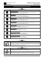
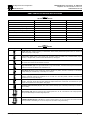
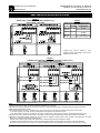
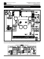
12095 NW 39 Street, Coral Springs, FL 33065-2516
Telephone: 954-346-4900; Fax: 954-346-3377
www.kbelectronics.com
"The Right Control for Your Application."
KB Electronics, Inc.
KBBC SERIES OPERATING INSTRUCTIONS
P5
P1
FIGURE 1
CONTROL LAYOUT AND GENERAL CONNECTION DIAGRAM
Notes: 1. If Key Switch is not used, a connection must be made between the red wire of Connector P1 (Terminal 3) and quick-connect
Terminal B+ for the control to operate. 2. To reset the control in wig-wag mode, return the Main Speed Potentiometer to the center position.
3. Run Forward and Run Reverse Switches are not used in wig-wag operation. 4. If wiring a fuse or circuit breaker, it must be wired in the
location shown, immediately after the battery positive (+) terminal. The Key Switch must be wired after the fuse or circuit breaker.
FIGURE 2
DESCRIPTION AND WIRING OF CONNECTORS
(A40140) – Rev. A00 – 6/10/2014
Page 1 of 4
12095 NW 39 Street, Coral Springs, FL 33065-2516
Telephone: 954-346-4900; Fax: 954-346-3377
www.kbelectronics.com
"The Right Control for Your Application."
KB Electronics, Inc.
KBBC SERIES OPERATING INSTRUCTIONS
TABLE 1
ADJUSTABLE TRIMPOTS
Trimpot Range
1
0.2
2.5
T-BRK
150
0
200
CL
4
0
25
IR
2
0.1
15
DECEL
2
0.1
15
ACCEL
0
Description
Timed Brake Delay (T-BRK):
Allows adjustment of the delay time before the brake engages after the control is put into the stop or brake mode.
Stop or brake is initiated by opening the Enable Switch or Key Switch or by closing inhibit terminals.
Adjustment Range: 0.2 – 2.5 Seconds; Factory Setting: 1 Second
Current Limit (CL):
Allows adjustment of current limit setpoint. Typically set to 1.5 times the full load current rating of the motor. When
the control is in Current Limit, the STATUS LED will illuminate red.
Adjustment Range: 0 – 200% of Jumper JB Setting; Factory Setting: 150%
IR Compensation (IR):
Allows adjustment of load compensation for different motors. Smaller motors require more compensation to
overcome losses in armature winding. Typically set by checking No Load to Full Load speed changes.
Adjustment Range: 0 – 25 Volts DC; Factory Setting: 4 Volts DC
Deceleration (DECEL):
Allows for controlled deceleration from full speed to zero speed. Decel works with all stop modes except inhibit.
When inhibit is used, the DECEL Trimpot has no effect, output will go to zero in 0.1 seconds.
Adjustment Range: 0.1 – 15 Seconds; Factory Setting: 2 Seconds
Acceleration (ACCEL):
Allows for controlled acceleration from zero to full speed. Acceleration is active in any turn-on condition, including
Enable, Key Switch, or release of inhibit.
Adjustment Range: 0.1 – 15 Seconds; Factory Setting: 2 Seconds
30
Minimum Speed (MIN):
Sets the minimum speed the motor will run.
Adjustment Range: 0 – 30% Base Speed; Factory Setting: 0%
100
Reverse Maximum Speed (RMAX):
Limits the maximum allowable speed in the reverse direction.
Adjustment Range: 50 – 100% Base Speed; Factory Setting: 100%
MIN
50
RMAX
100
60
FMAX
Forward Maximum Speed (FMAX):
Limits the maximum allowable speed in the forward direction.
Adjustment Range: 60 – 100% Base Speed; Factory Setting: 100%
TABLE 2
RUN RELAY OPERATION
Connector P5
Description
Run Relay Output Contacts Selection (P5): Provides Normally Open or Normally Closed relay output contacts
(use Jumper J8 to select N.O. or N.C. contacts). The Run Relay is engaged when the control is in the Run Mode.
The Run Relay is disengaged when the control is in the Stop Mode or for any fault condition (Main Speed
Potentiometer Fault (open lead), Over Temperature Fault, Overvoltage Fault, Undervoltage Fault, Motor Brake
Fault, Internal Fault (micro failure), and Timed Current Limit.
TABLE 3
DIAGNOSTIC LED INDICATORS
LED
Description
Power On: This green LED is illuminated when the Key Switch is engaged.
Status: Both green and red LEDs are used to indicate control status. See Table 4 on page 3.
(A40140) – Rev. A00 – 6/10/2014
Page 2 of 4
12095 NW 39 Street, Coral Springs, FL 33065-2516
Telephone: 954-346-4900; Fax: 954-346-3377
www.kbelectronics.com
"The Right Control for Your Application."
KB Electronics, Inc.
KBBC SERIES OPERATING INSTRUCTIONS
Control Status
TABLE 4
LED STATUS INDICATORS
Green LED
Red LED
Flash Rate*
Run
On
Off
Slow
Stop
On
Off
Quick
Current Limit (Warning)
Off
On
Steady
Undervoltage (Warning)
On
On
Slow
Overvoltage/Undervoltage Fault (Shutdown)
On
On
Quick
Overtemperature Fault (Shutdown)
On
On
Slow Alternating
Main Speed Potentiometer Fault (Shutdown)
On
On
Quick Alternating
Motor or Brake Fault (Shutdown)
On
On
Double Quick Alternating
Timed Current Limit
Off
On
Quick
*Flash Rate: Slow = 1 second on and 1 second off. Quick = 0.15 seconds on and 0.15 seconds off.
TABLE 5
SELECTABLE JUMPERS
Jumper
Description
Signal Input (J1): Voltage Following / Potentiometer. Selects either potentiometer speed control, or remote 0-5
Volts DC signal input. See page 4.
Speed Mode (J2): Wig-Wag / Single-Ended. Allows for selection of Wig-Wag speed control, (center of Main Speed
Potentiometer rotation (50%) is zero speed, fully clockwise (100%) is forward, fully counterclockwise (0%) is
reverse), or Single-Ended, (contact closure selects direction). See page 4.
Timed Current Limit (J3): Non Timed Current Limit / Timed Current Limit. Disables or enables the shutdown of
the control due to motor overcurrent after 7 seconds.
High Pedal Disable (J4): Non-High Pedal Disable / High Pedal Disable. In HPD the Main Speed Potentiometer
needs to be reset to zero before motor is allowed to run.
Stop Mode (J5): Decel / Fixed. Allows stop function (Enable, Key Switch, Direction Command) to use DECEL
Trimpot setting for controlled stop, or fixed stop of 0.1 second.
Latch Mode (J6): Off / On. Allows selection of how direction commands are activated. If latch is in "OFF" position,
direction commands need to be maintained to run. If Latch is in the "ON" position, direction commands are
momentary to run or stop. See page 4.
Cycle Mode (J7): Off / On. When the control is commanded to stop, an output relay closes to short motor leads
together. This action will act like a dynamic brake and impede motor travel. If this action is not desired, the cycle
jumper can be placed in the "ON" position. See page 4.
Run Relay Output Contacts (J8): NO / NC. Used to select Normally Open or Normally Closed output contacts of
the Run Relay.
Motor Voltage (JA): Sets the control for using voltage inputs of 12, 24, 36, or 48 Volts DC. This Jumper primarily
sets up the Overvoltage and Undervoltage set points.
CURRENT SELECTION (JB): Calibrates the control for motors rated 10, 20, 30 or 40 Amps. The Current Limit will
be set up based on this setting X 1.5. The CL Trimpot can be used to change this setting.
(A40140) – Rev. A00 – 6/10/2014
Page 3 of 4
12095 NW 39 Street, Coral Springs, FL 33065-2516
Telephone: 954-346-4900; Fax: 954-346-3377
www.kbelectronics.com
"The Right Control for Your Application."
KB Electronics, Inc.
KBBC SERIES OPERATING INSTRUCTIONS
FIGURE 3
SIGNAL INPUT CONNECTION DIAGRAMS (CONNECTOR P1)
WITH JUMPER J1 SETTINGS
TABLE 6
SIGNAL INPUT VOLTAGE REQUIREMENTS
Input Signal (Volts DC)
Direction Wig−Wag
Single−Ended
Maximum
4.7 + 0.3
4.7 + 0.3
Forward
(Run Forward Selected)
Neutral 2.5 ± 0.3
B−
B−
B+
B+
Maximum
0 + 0.3
Reverse
0 + 0.3
4.7 + 0.3
(Run Reverse Selected)
*Voltage input must be isolated. If using
multiple controls, their voltage inputs must be
isolated from each other.
FIGURE 4
FORWARD-STOP-REVERSE CONNECTION DIAGRAMS (CONNECTOR P3)
WITH JUMPER J2 AND J6 SETTINGS
Stop Forward
Run Forward
Stop Reverse
Stop Forward
Stop Forward
Run Reverse
Stop Reverse
Stop Reverse
Notes:
1. Inhibit Function (close to stop) is used for immediate deceleration (0.1 seconds).
2. Key Switch is used to enable power to the control. "Power On" LED will illuminate green to indicate that the Key Switch is activated.
3. Main Speed Potentiometer 5 k Ohm.
4. The mechanical life of the relay is 10 million cycles. The Cycle Jumper (J7) is useful for repetitive on/off cycling of the control.
In the "OFF" position (cycling off), the relay will engage to brake, when a stop command is given.
In the "ON" position (cycling on), the relay will not engage to brake, when a stop command is given. This extends the life of the relay.
5. Key Switch Function is used to enable power to the control. "Power On" light will illuminate to indicate the Key Switch is activated.
6. Momentary Limit Switch bypass protection. If the limit switch is engaged in either direction (Stop Forward or Stop Reverse), the same
direction run command will not allow continued travel.
Example: Run Forward, Stop Forward, will not allow Run Forward Command until Run Reverse is called.
If indexing is required, (Momentary Run Forward, Momentary Stop Forward, then Momentary Run Forward in the same direction),
the Stop Reverse (Connector P3-1) must be connected to COM (Connector P3-5) otherwise unit will not go forward the second time.
(A40140) – Rev. A00 – 6/10/2014
Page 4 of 4
RECONDITIONING THE BUS CAPACITORS
If this drive has been in storage for over one year it
is necessary to recondition the power supply bus
capacitors. To recondition the bus capacitors, apply
the DC input voltage, with the drive in the Stop
Mode, for a minimum of one hour. Not following this
procedure will cause the bus capacitors to fail.
(A40196) – Rev. A00 – 8/13/2013