1
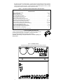
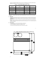
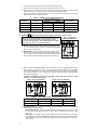
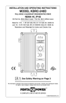
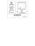
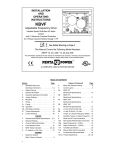
MODEL KBWD-15
Pulse Width Modulated
(PWM)
DC MOTOR
SPEED CONTROL
WHISPER DRIVE™
INSTALLATION
AND
OPERATING INSTRUCTIONS
See Safety Warning on Page 1 and
Application Note Warning on Page 2
The information contained in this manual is
intended to be accurate. However, the
manufacturer retains the right to make
changes in design which may not be included
herein.
Model KBWD-15
Rated 5.0 ADC @ 115 VAC 50/60 Hz
KB Part No. 8600
A COMPLETE LINE OF MOTOR DRIVES
© 1999 KB ELECTRONICS, INC.
TABLE OF CONTENTS
Section
Page
i.
Simplified Setup and Operating Instructions . . . . . . . . . . . . . . . . . . . . . . . . . . . . . . . . . . . . . . . . . . . . . . . . . . . . . 1
ii.
Safety Warning . . . . . . . . . . . . . . . . . . . . . . . . . . . . . . . . . . . . . . . . . . . . . . . . . . . . . . . . . . . . . . . . . . . . . . . . . . . . 1
iii. Application Note . . . . . . . . . . . . . . . . . . . . . . . . . . . . . . . . . . . . . . . . . . . . . . . . . . . . . . . . . . . . . . . . . . . . . . . . . . . 2
I.
General Information . . . . . . . . . . . . . . . . . . . . . . . . . . . . . . . . . . . . . . . . . . . . . . . . . . . . . . . . . . . . . . . . . . . . . . . . 2
II.
Mounting . . . . . . . . . . . . . . . . . . . . . . . . . . . . . . . . . . . . . . . . . . . . . . . . . . . . . . . . . . . . . . . . . . . . . . . . . . . . . . . . . 5
III. Initial Setup . . . . . . . . . . . . . . . . . . . . . . . . . . . . . . . . . . . . . . . . . . . . . . . . . . . . . . . . . . . . . . . . . . . . . . . . . . . . . . . 5
IV. Wiring . . . . . . . . . . . . . . . . . . . . . . . . . . . . . . . . . . . . . . . . . . . . . . . . . . . . . . . . . . . . . . . . . . . . . . . . . . . . . . . . . . . 7
V. DC Tachometer Input . . . . . . . . . . . . . . . . . . . . . . . . . . . . . . . . . . . . . . . . . . . . . . . . . . . . . . . . . . . . . . . . . . . . . . . 9
VI. Inhibit . . . . . . . . . . . . . . . . . . . . . . . . . . . . . . . . . . . . . . . . . . . . . . . . . . . . . . . . . . . . . . . . . . . . . . . . . . . . . . . . . . . 10
VII. Operation . . . . . . . . . . . . . . . . . . . . . . . . . . . . . . . . . . . . . . . . . . . . . . . . . . . . . . . . . . . . . . . . . . . . . . . . . . . . . . . 10
VIII. Trimpot Adjustments . . . . . . . . . . . . . . . . . . . . . . . . . . . . . . . . . . . . . . . . . . . . . . . . . . . . . . . . . . . . . . . . . . . . . . . 10
IX. Function Indicator Lamps . . . . . . . . . . . . . . . . . . . . . . . . . . . . . . . . . . . . . . . . . . . . . . . . . . . . . . . . . . . . . . . . . . . 12
X. Limited Warranty . . . . . . . . . . . . . . . . . . . . . . . . . . . . . . . . . . . . . . . . . . . . . . . . . . . . . . . . . . . . . . . . . . . . . . . . . . 18
TABLES
1.
Electrical Ratings & Mechanical Specifications . . . . . . . . . . . . . . . . . . . . . . . . . . . . . . . . . . . . . . . . . . . . . . . . . . . 3
2.
Plug-in Horsepower Resistor® Chart . . . . . . . . . . . . . . . . . . . . . . . . . . . . . . . . . . . . . . . . . . . . . . . . . . . . . . . . . . . 5
3.
Terminal Block Wiring Information . . . . . . . . . . . . . . . . . . . . . . . . . . . . . . . . . . . . . . . . . . . . . . . . . . . . . . . . . . . . . 7
4.
Field Connections . . . . . . . . . . . . . . . . . . . . . . . . . . . . . . . . . . . . . . . . . . . . . . . . . . . . . . . . . . . . . . . . . . . . . . . . . . 8
5.
KBWD-15 Parts List . . . . . . . . . . . . . . . . . . . . . . . . . . . . . . . . . . . . . . . . . . . . . . . . . . . . . . . . . . . . . . 13, 14, 15, 16
FIGURES
1.
Control Layout . . . . . . . . . . . . . . . . . . . . . . . . . . . . . . . . . . . . . . . . . . . . . . . . . . . . . . . . . . . . . . . . . . . . . . . . . . . . . 4
2.
Mechanical Specifications . . . . . . . . . . . . . . . . . . . . . . . . . . . . . . . . . . . . . . . . . . . . . . . . . . . . . . . . . . . . . . . . . . . 6
3.
AC Line and Armature Connection . . . . . . . . . . . . . . . . . . . . . . . . . . . . . . . . . . . . . . . . . . . . . . . . . . . . . . . . . . . . 7
4A. Full Voltage Field . . . . . . . . . . . . . . . . . . . . . . . . . . . . . . . . . . . . . . . . . . . . . . . . . . . . . . . . . . . . . . . . . . . . . . . . . . 8
4B. Half Voltage Field . . . . . . . . . . . . . . . . . . . . . . . . . . . . . . . . . . . . . . . . . . . . . . . . . . . . . . . . . . . . . . . . . . . . . . . . . . 8
5.
Remote Potentiometer Connection . . . . . . . . . . . . . . . . . . . . . . . . . . . . . . . . . . . . . . . . . . . . . . . . . . . . . . . . . . . . 9
6.
Analog Voltage Connection . . . . . . . . . . . . . . . . . . . . . . . . . . . . . . . . . . . . . . . . . . . . . . . . . . . . . . . . . . . . . . . . . . 9
7.
Microprocessor Connection . . . . . . . . . . . . . . . . . . . . . . . . . . . . . . . . . . . . . . . . . . . . . . . . . . . . . . . . . . . . . . . . . . 9
8.
Tachometer Connection . . . . . . . . . . . . . . . . . . . . . . . . . . . . . . . . . . . . . . . . . . . . . . . . . . . . . . . . . . . . . . . . . . . . . 9
9.
Inhibit Circuit Wiring . . . . . . . . . . . . . . . . . . . . . . . . . . . . . . . . . . . . . . . . . . . . . . . . . . . . . . . . . . . . . . . . . . . . . . . 10
10. KBWD-15 Schematic . . . . . . . . . . . . . . . . . . . . . . . . . . . . . . . . . . . . . . . . . . . . . . . . . . . . . . . . . . . . . . . 17
ii
i.
SIMPLIFIED SETUP AND OPERATING INSTRUCTIONS
IMPORTANT – You must read these simplified operating instructions before you proceed.
1.
Be sure AC line voltage is 115 VAC 50/60 Hz.
2.
Install the correct Plug-in Horsepower Resistor® according to motor current and/or horsepower.
Note: Disregard the horsepower rating marked on the
Plug-in Horsepower Resistor® since they are marked
for SCR controls. See table 2, page 5.
FACTORY SETTING OF TRIMPOTS
3.
Recheck connections: AC line to L1 and L2; armature to A+
and A- (use F+ and F- for shunt motor field connections only.)
Note: If motor runs in improper direction, interchange
armature leads.
4.
Nominal factory trimpot settings are as follows: (Expressed in % of full CW rotation).
ii. SAFETY WARNING! — PLEASE READ CAREFULLY
This product should be installed and serviced by a qualified technician, electrician or electrical maintenance
person familiar with its operation and the hazards involved. Proper installation, which includes wiring, mounting in
proper enclosure, fusing or other overcurrent protection and grounding, can reduce the chance of electric shocks,
fires or explosion in this product or products used with this product, such as electric motors, switches, coils, solenoids
or relays. Eye protection must be worn and insulated adjustment tools must be used when working with control under
power. This product is constructed of materials (plastics, metals, carbon, silicon, etc.) which may be a potential
hazard. Proper shielding, grounding and filtering of this product can reduce the emission of radio frequency
interference (RFI) which may adversely affect sensitive electronic equipment. If information is required on this
product, contact our factory. It is the responsibility of the equipment manufacturer and individual installer to supply
this safety warning to the ultimate user of this product. (SW effective 11/92)
This control may contain electronic Start/Stop and Enable circuits that can be used to start and stop the control.
However, these circuits are never to be used as safety disconnects since they are not fail-safe. Use only the AC line
for this purpose.
The input circuits of this control (tachometer, start/stop, inhibit, enable) are not isolated from AC line. Be sure
to follow all instructions carefully. Fire and/or electrocution can result due to improper use of this product.
See Application Note Warning on page 2.
1
This product complies with all CE directives pertinent at the time of manufacture. Contact factory
for detailed installation instructions and Declaration of Conformity. Installation of a CE approved
RFI filter (KBRF-200A, KB P/N 9945C or equivalent) is required. Additional shielded motor cable and/or
AC line cables may be required along with a signal isolator (KBSI-240D, KB P/N 9431 or equivalent).
iii.
APPLICATION NOTE:
WARNING!
1. PWM controls are designed with a single power transistor which is wired directly in series with
the motor. If for some reason this transistor short circuits, a "runaway" condition could occur
where the motor will almost instantaneously accelerate to full speed. This could cause physical
harm to an operator or user of the machinery or equipment on which the control is installed. In
some cases a proper sized fuse, when installed in series with the motor armature, will prevent
this "runaway" condition. Use extreme caution when applying PWM controls to certain
applications.
2. PWM controls emit substantial levels of radio frequency interference (RFI) compared to SCR
controls. The KBWD contains a built-in RFI filter which suppresses most of the RFI that would
normally be conducted and radiated via the AC line. However, some RFI can still be radiated and
conducted from the control and through the motor wires. Shielded cables and other means of
reducing the effect of RFI may have to be employed for some applications.
3. This control contains inhibit, enable and other circuits that can be used to turn the control "on"
and "off." Do not use these circuits as a safety disconnect. Use only the AC line for that purpose.
I.
GENERAL INFORMATION
The KBWD-15 Pulse Width Modulated (PWM) DC motor speed control provides excellent dynamic response
to load variations. The efficient PWM waveform produces an almost pure DC current to the motor (form
factor < 1.05) which has several advantages over a conventional SCR control. The PWM significantly lowers
audible motor noise and provides longer brush life. It also produces less motor heating which allows a
smaller, less costly motor to be used for most applications. Another advantage of PWM is higher output
voltage which provides increased output speed. In addition, pulse-by-pulse current sensing provides short
circuit protection.
A unique feature of the KBWD-15 control is the Plug-in Horsepower Resistor®. It eliminates the need for
recalibrating IR Comp and Current Limit when the control is used on various horsepower motors. The control
is factory set for armature feedback which provides excellent load regulation. For applications that require
superior performance, tachometer feedback is also provided. The KBWD-15 contains (I x t) overload
protection which will shut the control down if the motor is overloaded for a predetermined time. Diagnostic
LEDs for "Power On" and "Overload” (CL) indication are also provided.
2
RFI filtering is included as a standard feature. It greatly reduces conducted interference which could affect
sensitive equipment. The control contains barrier terminals as standard; however, quick disconnect
terminals can be provided as an option. A potentiometer (5K), isolated analog signal (0-10 VDC), or PWM
microprocessor output can be used to vary the output of the control.
TABLE 1 – ELECTRICAL RATINGS & MECHANICAL SPECIFICATIONS
Model KBWD-15 Rated 5.0 Amps DC @ 115 VAC 50/60 Hz
SPECIFICATIONS
Output Voltage Range (VDC) . . . . . . . . . . . . . . . . . . . . . . . . . . . . . . . . . . . . . . . . . . . . . . . . . . . . 0 – 130
Speed Range (Ratio) . . . . . . . . . . . . . . . . . . . . . . . . . . . . . . . . . . . . . . . . . . . . . . . . . . . . . . . . . . . . . 50:1
Operating Frequency (kHz) . . . . . . . . . . . . . . . . . . . . . . . . . . . . . . . . . . . . . . . . . . . . . . . . . . . . . . . . . >16
Form Factor (RMS / Avg Amps) . . . . . . . . . . . . . . . . . . . . . . . . . . . . . . . . . . . . . . . . . . . . . . . . . . . <1.05
Ambient Operating Range Temp (°C). . . . . . . . . . . . . . . . . . . . . . . . . . . . . . . . . . . . . . . . . . . . . . . . 0 – 45
Load Regulation (% Base Speed) . . . . . . . . . . . . . . . . . . . . . . . . . . . . . . . . . . . . . . . . . . . . . . . . . . . . . 1*
Timed CL Trimpot Range (TCL) (Seconds) . . . . . . . . . . . . . . . . . . . . . . . . . . . . . . . . . . . . . . . . . . . . 1 – 7
Acceleration Trimpot Range (ACCEL) (Seconds) . . . . . . . . . . . . . . . . . . . . . . . . . . . . . . . . . . . . 0.5 – 15
Minimum Speed Trimpot Range (MIN) (VDC) . . . . . . . . . . . . . . . . . . . . . . . . . . . . . . . . . . . . . . . . . 0 – 40
Maximum Speed Trimpot Range (MAX) (VDC) . . . . . . . . . . . . . . . . . . . . . . . . . . . . . . . . . . . . . . 70 – 130
Current Limit Trimpot Range (CL) (% Range Setting) . . . . . . . . . . . . . . . . . . . . . . . . . . . . . . . . . . 0 – 200
IR Comp Trimpot Range (IR) (VDC) . . . . . . . . . . . . . . . . . . . . . . . . . . . . . . . . . . . . . . . . . . . . . . . . 0 – 15
AC Line Voltage Regulation (% Base Speed) . . . . . . . . . . . . . . . . . . . . . . . . . . . . . . . . . . . . . . . . . . . 0.5
Analog Input Voltage (Voltage Following) (VDC) . . . . . . . . . . . . . . . . . . . . . . . . . . . . . . . . . . . . . . . 0 – 10
Speed Potentiometer - 5 watt (Ohms) . . . . . . . . . . . . . . . . . . . . . . . . . . . . . . . . . . . . . . . . . . . . . . . . . . 5K
*Based on motor having linear IR Comp characteristics.
®
PLUG-IN HORSEPOWER RESISTOR®
A Plug-in Horsepower Resistor must be installed to match the control to the motor
horsepower and armature current. See table 2, p. 5 for the correct value.
Plug-in Horsepower Resistors® are stocked by your distributor.
CAUTION: Be sure Plug-in Horsepower Resistor® is inserted completely into
mating socket.
3
FIG. 1 – CONTROL LAYOUT
Illustrates factory setting of jumpers and approximate setting of trimpots
4
The Plug-in Horsepower Resistor® will match the motor characteristics to the control without having to
calibrate the current limit (CL) and IR Compensation (IR) for most applications.
TABLE 2 – PLUG-IN HORSEPOWER RESISTOR® CHART
Plug-in Horsepower Resistor®
(Ohms)
90 VDC SCR Rated
Motor Horsepower
130 VDC PWM Rated
Motor Horsepower
3.3 – 5.0
0.1
1/3 – 1/2
1/2 – 3/4
2.5
0.18
1/4
1/3
1.3 – 2.0
0.25
1/8 – 1/6
1/6 – 1/4
0.7 – 1.0
0.51
1/15 – 1/10
1/12 – 1/8
0.4 – 0.6
1.0
1/30 – 1/20
1/20 – 1/15
0.1 – 0.3
2.0
1/50 – 1/100
Motor Armature Current
(Amps DC)
1/30 – 1/50
®
1. For motor current not on chart use next lowest value Plug-in Horsepower Resistor .
2. Disregard the horsepower ranges marked on Plug-in Horsepower Resistor® since they are not correct for PWM
controls.
II.
MOUNTING
The KBWD controls should be mounted on a flat surface and located in an area where it will not be exposed
to contaminants such as water, metal chips, solvents or excessive vibration. See fig. 2, p. 6 for Mechanical
Specifications.
Enclosure – When mounting in an enclosure, the air space should be large enough to provide adequate
ventilation. The maximum allowable ambient temperature at full rating is 45 °C/113 °F. Consult factory if more
information is required.
III.
INITIAL SETUP
1. Install proper size Plug-in Horsepower Resistor® (See table 2).
2. Connect the KBWD to a standard 115V 50/60 Hz AC line.
3. Follow the recommended supply wire sizes as per table 3 on page 7.
5
FIG. 2 – KBWD-15 MECHANICAL SPECIFICATIONS – INCHES / (mm)
6
4. Follow the National Electrical Code and other electrical codes that apply.
5. Connect control in accordance to AC line and armature connection. See fig. 3.
6. Ground (earth). The control should not be connected to ground (earth) since it does not contain a metal
chassis or enclosure. Attempting to ground control will cause catastrophic failure.
7. When using a step-down transformer (230 VAC to 115 VAC) be sure the VA rating of the transformer
is at least 3 times the VA rating of the motor.
TABLE 3 – TERMINAL BLOCK WIRING INFORMATION
IV.
Supply Wire Gauge (AWG, Cu)
Terminal Block
Designation
Connection
Designation
Minimum
Maximum
Maximum Tightening
Torque (lb-in)
TB1
L1, L2, A+, A-
22
12
7
TB2
F+, F-
22
14
5
TB3
I1, I2, P1, P2, P3
22
14
5
TB4
T+, T-
22
14
5
WIRING.
Warning! Read Safety Warning before attempting to use this control.
Warning! To avoid erratic operation do not bundle AC Line and
motor wires with potentiometer, voltage following, enable,
inhibit or other signal wiring. Use shielded cables on all signal
wiring over 12" (30 cm) – Do not ground shield.
FIG. 3 – AC LINE AND
ARMATURE CONNECTION
A. AC Line – Connect AC line (115 VAC 50/60 Hz) to terminals L1 and
L2. It is recommended that a line fuse or circuit breaker be installed
with a 10 amp – 125 VAC rating.
B. Motor Armature – Connect motor armature to terminals A+ and A-.
Be sure motor voltage corresponds to control output voltage range
(90 – 130 VDC). It is recommended that a fuse be installed in series
with the armature; choose a fuse rating equal to the motor rating.
7
C. Field – For Shunt Wound Motors Only. Do not use terminals F+ and F- for any purpose other than to
power the field on a shunt wound motor. Connect motor shunt field to terminals F+ and F- for 90VDC
motors with 100VDC fields. For motors with half voltage fields, 90VDC motors with 50VDC fields,
connect field to terminals F+ and L1. See table 4 for summary of field connections. See figures 4A and
4B for field wiring diagrams.
CAUTION – Shunt-Wound motors may be damaged if field remains powered without motor
rotating for an extended period of time.
FIG. 4A – FULL VOLTAGE FIELD
FIG. 4B – HALF VOLTAGE FIELD
TABLE 4 – FIELD CONNECTIONS (Shunt Wound Motors Only)
AC Line Voltage (VAC)
Motor Voltage (VDC)
Field Voltage (VDC)
115
90
100
Field Connection
F+, F-
115
90
50
F+, L1
D. Main Potentiometer – The control can be operated from a remote potentiometer, or from an isolated
analog voltage for voltage following.
i.
Remote Potentiometer – Connect remote potentiometer wires to terminals P1, P2 and P3, so that
the "high" side of the potentiometer connects to P3, the "wiper" to P2 and the "low" side to P1. (See
fig. 5, p. 9.)
ii. Analog Input – An isolated 0-10 VDC analog voltage can also be used to drive the control. Note:
If an isolated signal voltage is not available, an optional signal isolator can be installed (Model KBSI240D, P/N 9431). Connect the isolated input voltage to terminal P2 (positive) and P1 (negative).
(See fig. 6 p. 9.)
8
iii. Microprocessor Input – An isolated PWM signal from a microprocessor can be used to operate the
control. The output frequency should be 200 Hz or greater and should be derived from an
optocoupler with a transistor or operational amplifier signal output. (See fig. 7)
FIG. 5 – REMOTE
POTENTIOMETER CONNECTION
V.
FIG. 6 – ANALOG
VOLTAGE CONNECTION
FIG. 7 – MICROPROCESSOR
CONNECTION
DC TACHOMETER INPUT.
If tachometer feedback is required, an analog tach signal must be
connected to terminal block TB3. Note: For tachometer feedback,
Jumper J1 must be set for the proper tach voltage, and the IR
COMP must be set to minimum (CCW) position. Connect the
tachometer so that when the motor rotates, the positive tach
voltage lead is connected to T+ and the negative tach lead is
connected to T-. (See fig. 8.)
FIG. 8 – TACHOMETER
CONNECTION
Note: If the tach voltage is connected backwards, the control will drive
the motor at full speed only.
NOTE: Use the "7V" position for tachometer with 7 volts per 1000 RPM
and the "50V" position for tachometer with 50 volts per 1000 RPM.
(Set IR Comp to minimum for tach feedback.)
ARMATURE
FEEDBACK
TACH
7V/1000 RPM
TACH
50V/1000 RPM
9
VI.
INHIBIT
The control can be electronically stopped and started with the Inhibit circuit. To
"Stop" the control, terminals I1 & I2 must be shorted via a contact. The control
can be restarted by opening the contact.
FIG. 9 – INHIBIT
CIRCUIT WIRING
Note: The Inhibit should not be used as a safety disconnect. Use only the
AC line for that purpose. (See fig. 9, p. 10)
Note: The Inhibit Circuit is not isolated. Do not earth ground inhibit leads.
VII. OPERATION
WARNING! Read Safety Warning on page 1 before attempting to
operate the control or severe injury or electrocution can result.
After the control has been set up properly and the wiring has been completed, the
start-up procedure can begin. If AC power has been properly connected to the control, the "ON" LED
indicator will illuminate. Before starting, be sure the main potentiometer is in the minimum position. To start
the control, the potentiometer knob should be rotated clockwise; the motor should begin to rotate.
Note: If the motor rotates in the incorrect direction, it will be necessary to disconnect the main AC
power and reverse the armature wires.
VIII. TRIMPOT ADJUSTMENTS
The control contains trimpots which have been factory adjusted for most applications. Figure 1, p. 4
illustrates the location of the trimpots and their approximate adjustment positions. Some applications may
require readjustment of the trimpots in order to tailor the control to exact requirements. (See table 1, p. 3
for range and factory setting of all trimpots.) Readjust trimpots as follows:
WARNING. Do not adjust trimpots with main power on if possible. If adjustments are
made with power on, insulated adjustment tools must be used and safety glasses must be
worn. High voltage exists in this control. Electrocution and/or fire can result if caution is
not
exercised. Safety warning on page 1 must be read and understood before proceeding.
A. Minimum Speed (MIN) — The MIN trimpot is used to set the minimum voltage of the drive. This sets
the minimum speed of the motor. Adjust the MIN trimpot as follows:
1. Rotate Main Potentiometer to minimum speed position (full counterclockwise).
2. Increase setting of MIN trimpot so that motor runs at desired minimum speed.
10
B. Maximum Speed (MAX) — The MAX trimpot is used to set the maximum voltage of the drive. Adjust
the MAX trimpot as follows:
1. Rotate Main Potentiometer to maximum speed position (full clockwise).
2. Adjust MAX trimpot setting to desired setting of motor speed. (Caution: Do not exceed rated RPM
of motor.)
C. Acceleration (ACCEL) — The ACCEL trimpot sets the amount of time it takes the control to reach full
output. The trimpot is factory set to one (1) second. If more rapid acceleration is desired, rotate the
trimpot counterclockwise.
Note: Rapid ACCEL setting may cause the current limit circuit to activate which will extend the
acceleration time.
For a longer acceleration time, rotate ACCEL trimpot clockwise. 50% rotation represents approximately
seven (7) seconds and full rotation is approximately fifteen (15) seconds.
D. Current Limit (CL) — This trimpot is used to set the maximum amount of DC current that the motor can
draw. The amount of DC current is directly proportional to the motor torque. The CL trimpot is factory
set at 150% of the current established by the Plug-in Horsepower Resistor ® selection. (See table 2, p.
5.) Readjust the CL trimpot as follows: (Note: The "OL" indicator will light when the control is in
CL.)
1. Turn CL trimpot to minimum (CCW) position. Be sure proper value Plug-in Horsepower Resistor ®
is installed.
2. Wire in a DC ammeter in series with armature lead. Lock shaft of motor.
3. Apply power. Rotate CL trimpot CW until desired CL setting is reached (factory setting is 1.5 times
rated motor current).
CAUTION
1. Adjusting the CL above 150% of motor rating can cause overheating and demagnetization of
some PM motors. Consult motor manufacturer.
2. Do not leave the motor in a locked condition for more than a few seconds since armature
damage may occur.
E. IR Compensation (IR) — The IR comp circuit is used to stabilize motor speed under varying loads.
Note: If control is in Tach Feedback mode, the IR trimpot should be set to minimum - CCW.
Readjust the IR trimpot as follows:
11
1. Run the motor at approximately 30-50% of rated speed under no load and measure actual speed.
2. Load the motor to rated current. Rotate IR trimpot so that the loaded speed is the same as the
unloaded speed measured in E1.
Control is now compensated so that minimal speed change will occur over a wide range of motor
load.
Note: Too much IR Comp will cause unstable (oscillatory) operation.
F. Timed Current Limit (TCL) – This trimpot determines the approximate amount of time the drive will stay
in Current Limit before “timing out.” The trimpot has an adjustment range of 1 – 7 seconds and is factory
set for three (3) seconds. The trimpot can be reset according to the desired trip time. Rotating the
trimpot clockwise increases the trip time. This function provides motor overload protection.
IX.
FUNCTION INDICATOR LAMPS
The control contains two LED indicator lamps that reflect operational status.
A. Power On Indicator (ON) – This lamp will glow GREEN when the AC line is connected to the control.
B. Overload Indicator (OL) – When the motor is loaded to the current limit setpoint (CL setpoint is
established by the value of the Plug-in Horsepower Resistor®and the CL trimpot) this lamp will glow RED.
If the control is allowed to stay in CL and then “times out” in Timed Current Limit, the CL LED will remain
illuminated, until the control is restarted with the On/Off or Inhibit Switch. If the OL LED remains
illuminated during control operation, a fault condition may exist. Possible causes for this condition are
as follows:
1. Motor is overloaded - check motor amps with DC ammeter in series with armature. (If motor is shunt
type, field may be open or not receiving proper voltage.)
2. Motor may be defective - check motor for shorts or grounds.
3. The CL may be set too low - check value of Plug-in Horsepower Resistor® and CL trimpot.
Note: The horsepower ranges marked on the Plug-in Horsepower Resistor® are marked for SCR
controls (See table 2 p. 5).
NOTE: In some applications, especially those requiring the motor to cycle on and off or to be changed
from one speed to another, the OL indicator may blink indicating a transient overload. This may be a
normal condition for the application.
12
X – LIMITED WARRANTY
For a period of 18 months from date of original purchase, KB will repair or replace without charge devices
which our examination proves to be defective in material or workmanship. This warranty is valid if the unit
has not been tampered with by unauthorized persons, misused, abused, or improperly installed and has been
used in accordance with the instructions and/or ratings supplied. The foregoing is in lieu of any other
warranty or guarantee, expressed or implied, and we are not responsible for any expense, including
installation and removal, inconvenience, or consequential damage, including injury to any person, caused
by items of our manufacture or sale. Some states do not allow certain exclusions or limitations found in this
warranty so that they may not apply to you. In any event, KB's total liability, under all circumstances, shall
not exceed the full purchase price of this unit. (rev 4/88)
KB ELECTRONICS, INC.
12095 NW 39th Street, Coral Springs, FL 33065 • (954) 346-4900 • Fax (954) 346-3377
Outside Florida Call TOLL FREE (800) 221-6570 • E-mail – [email protected]
www.kbelectronics.com
(A40268) – Rev. B – 4/99