1
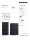
General Installation Manual
SPECIFICATIONS
Standard Models – HIP-xxxNKHE5, HIP-xxxNKHE5-2
E lectrical S pecifications
HI P-2 15NKHE5,
HIP-21 5NKHE5-2
HIP-214 NKHE5
V
72
215
42.0
5.13
51.6
5.61
HIT*
1000
72
214
41.9
5.12
51.5
5.60
HIT*
1000
72
210
41.3
5.09
50.9
5.57
HIT*
1000
72
205
40.7
5.05
50.3
5.54
HIT*
1000
72
200
40.0
5.00
49.6
5.50
HIT*
1000
A
15
15
15
15
15
3
3
M odel
Cell Number in Series
Rated Power, W atts (Pm ax)
M axim um Power V oltage (Vpm )
M axim um Power Current (Ipm)
Op en Circuit V oltage (Voc)
S hort Circuit Current (Isc)
Cell Type
M axim um System V oltage (Voc)
M axim um over-current protection
rating
Factory Installed Bypass Diodes
W
V
A
V
A
HIP-21 0NKHE5 , HIP -2 05NKHE 5, HIP-200 NKHE5,
HIP-210 NKHE5-2 HIP-20 5NKHE5 -2 HIP -2 00NKHE 5-2
3
3
3
HIT* : Hetero junction with Intrinsic Thin-layer
M echanical Specifications
HI P-2 15NKHE5,
HIP-21 5NKHE5-2
M odel
Leng th
W idth
Height
W eight
HIP-214 NKHE5
HIP-21 0NKHE5 , HIP -2 05NKHE 5, HIP-200 NKHE5,
HIP-210 NKHE5-2 HIP-20 5NKHE5 -2 HIP -2 00NKHE 5-2
1580
mm
mm
mm
kg
798
35
15.0
Dimensions
(Module type: HIP-xxxNKHE5, HIP-xxxNKHE5-2 ・・・with
connector and cable)
・・
Dimension in mm
Backside
* The positions of the holes are all symmetry
against the center of the module.
Section A-A’
Section B-B’
Note) a module is installed using 4 points,
symmetrical mounting within setting range (shaded).
Front
Side
Figure 2-1: Dimensions
5